
Related Manuals for E-Jet Sport EIR008

Summary of Contents for E-Jet Sport EIR008
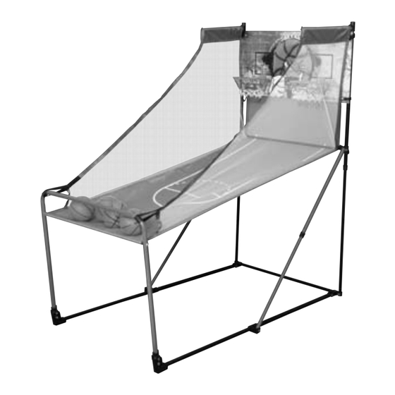
- Page 1 MODEL: EIR008 NAME: JUNIOR PORTABLE BASKETBALL ARCADE GAME ASSEMBLY INSTRUCTIONS WE ENCOURAGE OUR CUSTOMERS TO LEAVE REVIEWS OF OUR PRODUCTS ON THE RETAILER'S WEBSITE WHERE THE PRODUCT WAS PURCHASED.
-
Page 2: Assembly Tips
ASSEMBLY TIPS: 1 - Please read the instructions carefully, and follow all assembly, operation or safety instructions properly in order to avoid damage or injury. 2 - Some figures or drawings may not look exactly like your product. Please read and understand the text before beginning each assembly step. -
Page 3: Parts List
PARTS LIST Metal Tube Metal Tube Connect Tube Metal Tube (1pc) (1pc) (1pc) (1pc) Front Tube Front Handrail Basketball Backboard Scoreboard (1pc) (1pc) (1pc) (1pc) Basketball Rim Trigger Basketball Rim Net Ball Ramp with Stop Net (2pcs) (2pcs) (2pcs) (1pc) Board Clips M5 X 35MM M5 X 25MM... - Page 4 ASSEMBLY INSTRUCTIONS FIG.1 FIG.2...
- Page 5 FIG.3 X 10 FIG.3-1 Back FIG.3-2 FIG.3-3...
- Page 6 FIG.4 FIG.5...
- Page 7 FIG.6 FIG.7 FIG.7-1 FIG.7-3 FIG.7-2 Notice: Make sure the poles are locked...
- Page 8 FIG.8 FIG.9 FIG.9-1 FIG.9-2 Press the snap lock and make sure both locks are fit perfectly into the holes of plastic connectors.
- Page 9 FIG.10 FIG.11...
- Page 10 FIG.12 FIG.12-1 FIG.12-2 Notice: Make sure the poles are locked.
- Page 11 FIG.13 FIG.13-1 FIG.13-2 FIG.13-1 FIG.13-2...
- Page 12 FIG.14 Back FIG.14-1 FIG.14-2...
- Page 13 FIG.15 FIG.15-2 Please rope the velcro twice around the conner of bar. Make sure the stop net is tight. FIG.15-1 WARNING: 1) Requires 3 “AAA” batteries (not included). 2) Batteries must be installed according to the correct polarization (+ and -) YOU ARE NOW READY TO PLAY!
- Page 15 1. Pull up the lock device. If you find the lock device is difficult to pull up, please pull the pole toward your position gently. 2. Turn the lock device clockwise 3. make sure the lock devices stay securely in unlock position...
- Page 16 Press the snap button on the both poles and push the poles into each other about 1” deep. Repeat the same step on the other side. Notice: Don’t push the poles all the way to each other.
- Page 17 FIG.6 FIG.6-1 FIG.6-2 Push the frame downward to the end. Notice: During this step, if you find the telescope tubes on each side aren’t closed at the same time, please stop and pull the frame upward and repeat this action again. Press the snap button on the both poles at the same time by using both hands.
- Page 18 FIG.7 Pull up the lower frame to 90 degree. FIG.8 FIG.8-1 Press the snap button on the both poles and push the poles into each other about 1” deep. Repeat the same step on the other side. Notice: Don’t push the poles all the way to each other.
- Page 19 FIG.8-2 FIG.8-3 Push the frame downward to the end. Notice: During this step, if you find the telescope tubes on each side aren’t closed at the same time, please stop and pull the frame upward and repeat this action again. FIG.9 FIG.9-1...
- Page 20 FIG.9-2 FIG.10...
- Page 21 HOW TO SET UP THE ARCADE FIG.1 FIG.1-1 FIG.1-2 FIG.1-3...
- Page 22 FIG.2 Pull the frame to upward until the snap buttons are locked on both sides. FIG.3...
- Page 23 FIG.4...
- Page 24 FIG.5 Pull the frame to upward until the snap buttons are locked on both sides. FIG.6 Adjust the telescope poles length until the snap buttons are locked on both tubes.
- Page 25 FIG.7 FIG.8 FIG.8-1 Turn the lock device anticlockwise to release the lock device. You should hear 2 “click” sounds. FIG.8-2 Pull up the frame until the lock devices are in lock position Make sure the lock devices stay securely in lock position Notice: If the frame still can be moved all the way to the floor, it means the lock devices are not in the lock position.
- Page 26 FIG.9 1. Press the snap buttons 2. Move the pole upward 3. Make sure the snap buttons are locked by plastic connector.
Need help?
Do you have a question about the EIR008 and is the answer not in the manual?
Questions and answers