Table of Contents
Advertisement
Quick Links
AccuPro 7000-TS™
Scaletron Industries, LTD 53 Appletree Lane Plumsteadville, PA 18949
Toll Free: 1-800-257-5911 (USA & Canada)
Phone: (+1) 215-766-2670 (International)
Fax: (+1) 215-766-2672
info@scaletronscales.com
All information contained in this document is confidential to Scaletron Industries, Ltd. No license is expressed or implied, under
any patent, copyright or trade secret right is granted or implied by the conveyance of this document. No part of this document
may be reproduced, transmitted, transcribed, stored in a retrieval system, translated into any language or computer language, in
any form or by any means, electronic, mechanical, magnetic, optical, chemical, manual, or otherwise without the prior written
permission of Scaletron Industries, Ltd.
Copyright© 2023 Scaletron Industries, Ltd
All Rights Reserved r7
AccuPro 7000-TS™ Operator Manual r7
Operator Manual
1
177
Page
of
Advertisement
Table of Contents

Related Manuals for Scaletron AccuPro 7000-TS

Summary of Contents for Scaletron AccuPro 7000-TS
- Page 1 All information contained in this document is confidential to Scaletron Industries, Ltd. No license is expressed or implied, under any patent, copyright or trade secret right is granted or implied by the conveyance of this document. No part of this document...
-
Page 2: Table Of Contents
AccuPro 7000-TS™ Operator Manual r7 Table of Contents 1 Introduction ......................... 12 1.1 Scope .......................... 12 1.2 Acronyms and Abbreviations ..................12 1.3 Definitions ........................13 2 Hardware and Specifications ..................13 2.1 Analog Output Specifications ..................15 2.2 Relay Specifications ....................15 2.3 Modbus Specifications .................... - Page 3 AccuPro 7000-TS™ Operator Manual r7 5.9 Reset Settings ......................100 6 Calibration ......................... 101 6.1 Standard Calibration: Dead Load ................102 6.2 Standard Calibration: Dead Load Sample ..............103 6.3 Standard Calibration: Calibration Weight ..............106 6.4 Standard Calibration: Calibration Weight Sample ........... 107 6.5 Standard Calibration: Calibration Weight Value .............
- Page 4 AccuPro 7000-TS™ Operator Manual r7 8 Status Check ....................... 132 8.1 Indicator Light ......................134 8.2 Status Check: Errors ....................135 8.3 Status Check: Current Errors ..................136 8.4 Status Check: Error Log ................... 137 8.5 Status Check: Alarms ....................138 8.6 Status Check: Current Alarms ..................
- Page 5 AccuPro 7000-TS™ Operator Manual r7 10 Batch Control ......................174 10.1 Batch Control: Setup ....................175 10.2 Batch Control: Display ................... 176 10.3 Batch Control: Confirmation .................. 177 Copyright© 2023 Scaletron Industries, Ltd Page All Rights Reserved r7...
- Page 6 AccuPro 7000-TS™ Operator Manual r7 Figure 1: Bottom Main Plate ..................... 18 Figure 2: Top Plate (Color) ....................19 Figure 3: Top Plate (Draft) ....................22 Figure 4: User Connection Diagram .................. 23 Figure 5: User Connection Numbering Legend Tables ............. 24 Figure 6: Home Screen ......................
- Page 7 AccuPro 7000-TS™ Operator Manual r7 Figure 28: Channel 1 / 2 / 3 Weight Display 4 ..............50 Figure 29: Channel 1 / 2 / 3 Weight Display 5 ..............51 Figure 30: Channel 1 / 2 / 3 Weight Display 6 ..............52 Figure 31: Channel 1 / 2 / 3 Weight Display 7 ..............
- Page 8 AccuPro 7000-TS™ Operator Manual r7 Figure 55: Channel 1 / 2 / 3 / 4 Feed Rate Display 2 ............77 Figure 56: Channel 1 / 2 / 3 / 4 Feed Rate Display 3 ............78 Figure 57: Channel 1 / 2 / 3 / 4 Feed Rate Display 4 ............79 Figure 58: Channel 1 / 2 / 3 / 4 Feed Rate Options 1 ............
- Page 9 AccuPro 7000-TS™ Operator Manual r7 Figure 82: Standard Calibration: Dead Load Sample Success ........104 Figure 83: Standard Calibration: Dead Load Sample Error ..........105 Figure 84: Standard Calibration: Calibration Weight ............. 106 Figure 85: Standard Calibration: Calibration Weight Sample ........107 Figure 86: Standard Calibration: Calibration Weight Sample Success ......
- Page 10 AccuPro 7000-TS™ Operator Manual r7 Figure 109: Developer Options: Erase Memory ............. 131 Figure 110: Status Check Home 1 ................... 132 Figure 111: Status Check Home 2 ................... 133 Figure 112: Indicator Light Table ................... 134 Figure 113: Status Check: Errors ..................135 Figure 114: Status Check: Current Errors ...............
- Page 11 AccuPro 7000-TS™ Operator Manual r7 Figure 136: System Info: Modbus Address Map 1 ............158 Figure 137: System Info: Modbus Address Map 2 ............159 Figure 138: System Info: Temperature Adjustment ............160 Figure 139: System Info: System Clock ................161 Figure 140: System Info: Set Time and Date ..............
-
Page 12: Introduction
AccuPro 7000-TS™ Operator Manual r7 1 Introduction The AccuPro 7000-TS™ is a weight and volume measurement system offering up to 4- channel support. Its real-time measurement allows for precise monitoring during the process of filling or emptying a chemical substance container. The indicator is designed... -
Page 13: Definitions
Load Cell Amplifier: amplifies the millivolt signal generated from the scale base into a 4-20mA signal for the PLC • Measurement System: describes a complete AccuPro 7000-TS™ • Net Weight: the actual weight of material without the presence of a tank or container. - Page 14 AccuPro 7000-TS™ Operator Manual r7 Operational 2000 meters (maximum) Altitude Operational 20% to 90% non-condensing Relative Humidity Enclosure Nominal Size: 10 x 8 x 6 Inches (Height, Width, Depth) with hinged cover Weight: 6 lbs. (approx. maximum) Material: Opaque Polycarbonate, UL Listed Type 4X NEMA Location Recommendation: The enclosure should not be in an area with extreme weather conditions or heavy amounts of liquid soaking.
-
Page 15: Analog Output Specifications
AccuPro 7000-TS™ Operator Manual r7 External: Support for a user-supplied alarm. An alarm relay is available with SPDT contact configuration (NO-COM-NC). Switching capacity of 3A (maximum) @ 250 VAC or 30 VDC. Inductive loads are not recommended. Controls Control Type: touchscreen 2.1 Analog Output Specifications... -
Page 16: Modbus Specifications
AccuPro 7000-TS™ Operator Manual r7 Maximum Switching 250VAC/3A, 30VDC/3A Capacity Trigger Alarm: When weight setpoint setting “trigger alarm” is Relay Configuration Options active, a weight setpoint will trigger an alarm when active 2.3 Modbus Specifications Modbus Communication Protocol: Modbus TCP through Ethernet... - Page 17 AccuPro 7000-TS™ Operator Manual r7 Ch 3 Net Weight: HR: 414024 Modbus Address Map Gross Weight: HR: 414026 Net Weight Percentage: HR 414028 (outputs 0-100) Gross Weight Percentage: HR: 414030 (outputs 0-100) Display Unit: HR: 414032 Tare: HR: 414034 Error Active: C: 6506...
-
Page 18: System Assembly
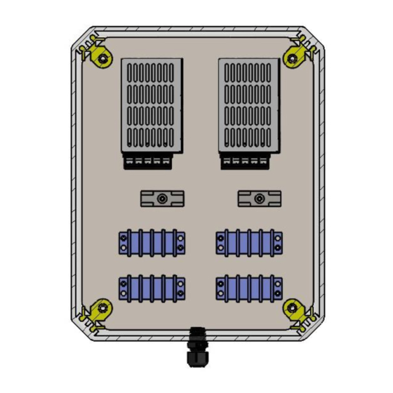
AccuPro 7000-TS™ Operator Manual r7 3 System Assembly The AccuPro 7000-TS uses a multi-layered design approach. The bottom main plate contains the power supplies and fuse. The top plate contains all relay modules (dependent on user configuration) and terminal block strip connections to be made by the user. Connections from the PLC are made through shielded cable to aid in EMI shielding. - Page 19 AccuPro 7000-TS™ Operator Manual r7 Figure 2: Top Plate (Color) Contains terminal strip connections and relays. The top plate will vary depending on configuration. This plate is what the user connects to. Copyright© 2023 Scaletron Industries, Ltd Page All Rights Reserved r7...
-
Page 20: Factory Configuration
Scale-Base at the factory. If you experience a problem with this equipment, please disconnect all accessories to this equipment to isolate the problem. Scaletron has taken great care to be sure the equipment is fully functional within factory specifications before it leaves our facility. -
Page 21: User Connections And Wiring
AccuPro 7000-TS™ Operator Manual r7 3.3 User Connections and Wiring Before making external connections, it is recommended that the control-panel first be connected to a power source to confirm normal operation. If all is functioning properly, you should see the home screen (see figure 6). - Page 22 AccuPro 7000-TS™ Operator Manual r7 Figure 3: Top Plate (Draft) Contains the label of all terminal strips and relays for user connections. The top plate will vary depending on configuration. This is the plate the user connects to. Copyright© 2023 Scaletron Industries, Ltd...
- Page 23 AccuPro 7000-TS™ Operator Manual r7 Figure 4: User Connection Diagram Contains a number for each user connection point. View the user connection numbering legend for more information on connections. Copyright© 2023 Scaletron Industries, Ltd Page All Rights Reserved r7...
- Page 24 AccuPro 7000-TS™ Operator Manual r7 Terminal 1 CH1 Base Inputs Excitation (+) Signal (+) Signal Return (-) Excitation Return (-) Shield Terminal 2 CH2 Base Inputs Excitation (+) Signal (+) Signal Return (-) Excitation Return (-) Shield Terminal 3 CH3 Base...
- Page 25 AccuPro 7000-TS™ Operator Manual r7 Terminal 4 CH4 Base Inputs Excitation (+) Signal (+) Signal Return (-) Excitation Return (-) Shield Terminal 5 CH1-2 4-20 mA Out Outputs CH1 Signal (+) Net Wt or Feed Rt (+) CH1 Signal Return (-)
- Page 26 AccuPro 7000-TS™ Operator Manual r7 1 or 2 Channel Indicator 3 or 4 Channel Indicator Relay 1 CH1 SPS Relay 1 CH1 SPS COM1 COM1 COM2 COM2 CH2 SPS COM3 COM3 COM4 COM4 Relay 2 CH2 SPS Relay 2 CH3 SPS...
- Page 27 AccuPro 7000-TS™ Operator Manual r7 Relay 3 External Buzzer Relay 4 Alarm Active Relay 5 Weight SP Active Relay 6 Max Net Weight Copyright© 2023 Scaletron Industries, Ltd Page All Rights Reserved r7...
-
Page 28: System Operation
AccuPro 7000-TS™ Operator Manual r7 4 System Operation The AccuPro 7000-TS allows the user to monitor and data log chemicals by weight or volume in pounds, kilograms, gallons, or liters. The user is also able to monitor feed rate and operate a batch control function. -
Page 29: Weight Display
AccuPro 7000-TS™ Operator Manual r7 4.1 Weight Display The user can access the display screens by pressing the “Wt Display” button on the home screen. While in any display, the user can navigate by pressing the "Next" or “Prev" button on any display. - Page 30 AccuPro 7000-TS™ Operator Manual r7 Figure 8: Channel 1 Display 2 Displays net percent, gross percent, net weight graph, and weight setpoints NOTE: Only available when weight setpoints are enabled NOTE: The amount of weight setpoints displayed will vary based on configuration Copyright©...
- Page 31 AccuPro 7000-TS™ Operator Manual r7 Figure 9: Channel 1 Display 3 Displays net weight, gross weight, and net weight graph Copyright© 2023 Scaletron Industries, Ltd Page All Rights Reserved r7...
- Page 32 AccuPro 7000-TS™ Operator Manual r7 Figure 10: Channel 1 Display 4 Displays net percent, gross percent, and net weight graph Copyright© 2023 Scaletron Industries, Ltd Page All Rights Reserved r7...
- Page 33 AccuPro 7000-TS™ Operator Manual r7 Figure 11: Channel 1 Display 5 Displays net weight graph, gross weight graph, net weight, and gross weight Copyright© 2023 Scaletron Industries, Ltd Page All Rights Reserved r7...
- Page 34 AccuPro 7000-TS™ Operator Manual r7 Figure 12: Channel 1 Display 6 Displays net weight, gross weight, 4-20mA out, and tare Copyright© 2023 Scaletron Industries, Ltd Page All Rights Reserved r7...
- Page 35 AccuPro 7000-TS™ Operator Manual r7 Figure 13: Channel 1 Display 7 Displays net percent, gross percent, 4-20mA out, and tare Copyright© 2023 Scaletron Industries, Ltd Page All Rights Reserved r7...
- Page 36 AccuPro 7000-TS™ Operator Manual r7 Figure 14: Channel 1 Display 8 Displays net weight and net weight graph Copyright© 2023 Scaletron Industries, Ltd Page All Rights Reserved r7...
- Page 37 AccuPro 7000-TS™ Operator Manual r7 Figure 15: Channel 1 Display 9 Displays net percent and net weight graph Copyright© 2023 Scaletron Industries, Ltd Page All Rights Reserved r7...
- Page 38 AccuPro 7000-TS™ Operator Manual r7 Figure 16: Channel 1 Display 10 Displays net weight Copyright© 2023 Scaletron Industries, Ltd Page All Rights Reserved r7...
- Page 39 AccuPro 7000-TS™ Operator Manual r7 Figure 17: Channel 1 Display 11 Displays net percent Copyright© 2023 Scaletron Industries, Ltd Page All Rights Reserved r7...
- Page 40 AccuPro 7000-TS™ Operator Manual r7 Figure 18: Channel 1 / 2 Display 1 Displays Ch 1 net weight, Ch 1 gross weight, Ch 2 net weight, and Ch 2 gross weight Copyright© 2023 Scaletron Industries, Ltd Page All Rights Reserved r7...
- Page 41 AccuPro 7000-TS™ Operator Manual r7 Figure 19: Channel 1 / 2 Display 2 Displays Ch 1 net percent Ch 1 gross percent, Ch 2 net percent, and Ch 2 gross percent Copyright© 2023 Scaletron Industries, Ltd Page All Rights Reserved r7...
- Page 42 AccuPro 7000-TS™ Operator Manual r7 Figure 20: Channel 1 / 2 Display 3 Displays Ch 1 4-20mA out, Ch 1 tare, Ch 2 4-20mA out, and Ch 2 tare Copyright© 2023 Scaletron Industries, Ltd Page All Rights Reserved r7...
- Page 43 AccuPro 7000-TS™ Operator Manual r7 Figure 21: Channel 1 / 2 Display 4 Displays Ch 1 net weight, Ch 1 net weight graph, Ch 2 net weight, and Ch 2 net weight graph Copyright© 2023 Scaletron Industries, Ltd Page All Rights Reserved r7...
- Page 44 AccuPro 7000-TS™ Operator Manual r7 Figure 22: Channel 1 / 2 Display 5 Displays Ch 1 net weight, Ch 1 gross weight graph, Ch 2 net weight graph, and Ch 2 gross weight graph Copyright© 2023 Scaletron Industries, Ltd Page...
- Page 45 AccuPro 7000-TS™ Operator Manual r7 Figure 23: Channel 1 / 2 Display 6 Displays Ch 1 net weight graph, Ch 1 gross weight graph, Ch 2 net weight graph, and Ch 2 gross weight graph Copyright© 2023 Scaletron Industries, Ltd...
- Page 46 AccuPro 7000-TS™ Operator Manual r7 Figure 24: Channel 1 / 2 Display 7 Displays Ch 1 net weight, Ch 2 net weight, and weight setpoints NOTE: Only available when weight setpoints are enabled NOTE: The amount of weight setpoints displayed will vary based on configuration Copyright©...
- Page 47 AccuPro 7000-TS™ Operator Manual r7 Figure 25: Channel 1 / 2 / 3 Display 1 Displays Ch 1 net weight, Ch 2 net weight, and Ch 3 net weight Copyright© 2023 Scaletron Industries, Ltd Page All Rights Reserved r7...
- Page 48 AccuPro 7000-TS™ Operator Manual r7 Figure 26: Channel 1 / 2 / 3 Display 2 Displays Ch 1 gross weight, Ch 2 gross weight, and Ch 3 gross weight Copyright© 2023 Scaletron Industries, Ltd Page All Rights Reserved r7...
- Page 49 AccuPro 7000-TS™ Operator Manual r7 Figure 27: Channel 1 / 2 / 3 Display 3 Displays Ch 1 net percent, Ch 2 net percent, and Ch 3 net percent Copyright© 2023 Scaletron Industries, Ltd Page All Rights Reserved r7...
- Page 50 AccuPro 7000-TS™ Operator Manual r7 Figure 28: Channel 1 / 2 / 3 Display 4 Displays Ch 1 gross percent, Ch 2 gross percent, and Ch 3 gross percent Copyright© 2023 Scaletron Industries, Ltd Page All Rights Reserved r7...
- Page 51 AccuPro 7000-TS™ Operator Manual r7 Figure 29: Channel 1 / 2 / 3 Display 5 Displays Ch 1 4-20mA out, Ch 2 4-20mA out, and Ch 3 4-20mA out Copyright© 2023 Scaletron Industries, Ltd Page All Rights Reserved r7...
- Page 52 AccuPro 7000-TS™ Operator Manual r7 Figure 30: Channel 1 / 2 / 3 Display 6 Displays Ch 1 tare, Ch 2 tare, and Ch 3 tare Copyright© 2023 Scaletron Industries, Ltd Page All Rights Reserved r7...
- Page 53 AccuPro 7000-TS™ Operator Manual r7 Figure 31: Channel 1 / 2 / 3 Display 7 Displays Ch 1 net weight graph, Ch 2 net weight graph, and Ch 3 net weight graph Copyright© 2023 Scaletron Industries, Ltd Page All Rights Reserved r7...
- Page 54 AccuPro 7000-TS™ Operator Manual r7 Figure 32: Channel 1 / 2 / 3 Display 8 Displays Ch 1 gross weight graph, Ch 2 gross weight graph, and Ch 3 gross weight graph Copyright© 2023 Scaletron Industries, Ltd Page All Rights Reserved r7...
- Page 55 AccuPro 7000-TS™ Operator Manual r7 Figure 33: Channel 1 / 2 / 3 Display 9 Displays weight setpoints NOTE: Only available when weight setpoints are enabled Copyright© 2023 Scaletron Industries, Ltd Page All Rights Reserved r7...
- Page 56 AccuPro 7000-TS™ Operator Manual r7 Figure 34: Channel 1 / 2 / 3 / 4 Display 1 Displays Ch 1 net weight, Ch 2 net weight, Ch 3 net weight, and Ch 4 net weight Copyright© 2023 Scaletron Industries, Ltd...
- Page 57 AccuPro 7000-TS™ Operator Manual r7 Figure 35: Channel 1 / 2 / 3 / 4 Display 2 Displays Ch 1 gross weight, Ch 2 gross weight, Ch 3 gross weight, and Ch 4 gross weight Copyright© 2023 Scaletron Industries, Ltd...
- Page 58 AccuPro 7000-TS™ Operator Manual r7 Figure 36: Channel 1 / 2 / 3 / 4 Display 3 Displays Ch 1 net percent, Ch 2 net percent, Ch 3 net percent, and Ch 4 net percent Copyright© 2023 Scaletron Industries, Ltd...
- Page 59 AccuPro 7000-TS™ Operator Manual r7 Figure 37: Channel 1 / 2 / 3 / 4 Display 4 Displays Ch 1 gross percent, Ch 2 gross percent, Ch 3 gross percent, and Ch 4 gross percent Copyright© 2023 Scaletron Industries, Ltd...
- Page 60 AccuPro 7000-TS™ Operator Manual r7 Figure 38: Channel 1 / 2 / 3 / 4 Display 5 Displays Ch 1 4-20 mA out, Ch 2 4-20 mA out, Ch 3 4-20 mA out, and Ch 4 4-20 mA out Copyright© 2023 Scaletron Industries, Ltd...
- Page 61 AccuPro 7000-TS™ Operator Manual r7 Figure 39: Channel 1 / 2 / 3 / 4 Display 6 Displays Ch 1 tare, Ch 2 tare, Ch 3 tare, and Ch 4 tare Copyright© 2023 Scaletron Industries, Ltd Page All Rights Reserved r7...
- Page 62 AccuPro 7000-TS™ Operator Manual r7 Figure 40: Channel 1 / 2 / 3 / 4 Display 7 Displays Ch 1 net weight graph, Ch 2 net weight graph, Ch 3 net weight graph, and Ch 4 net weight graph Copyright© 2023 Scaletron Industries, Ltd...
- Page 63 AccuPro 7000-TS™ Operator Manual r7 Figure 41: Channel 1 / 2 / 3 / 4 Display 8 Displays Ch 1 gross weight graph, Ch 2 gross weight graph, Ch 3 gross weight graph, and Ch 4 gross weight graph Copyright© 2023 Scaletron Industries, Ltd...
- Page 64 AccuPro 7000-TS™ Operator Manual r7 Figure 42: Channel 1 / 2 / 3 / 4 Display 9 Displays weight setpoints NOTE: Only available when weight setpoints are enabled Copyright© 2023 Scaletron Industries, Ltd Page All Rights Reserved r7...
-
Page 65: Feed Rate Display
AccuPro 7000-TS™ Operator Manual r7 4.2 Feed Rate Display The user can access the display screens by pressing the “FR Display” button on the home screen. The user can reset all feed rate functions by pressing “Reset”. The user can pause all feed rate functions by pressing “Pause”. - Page 66 AccuPro 7000-TS™ Operator Manual r7 Figure 44: Channel 1 / 2 Feed Rate Display 1 Displays Ch 1 current feed rate and Ch 2 current feed rate Copyright© 2023 Scaletron Industries, Ltd Page All Rights Reserved r7...
- Page 67 AccuPro 7000-TS™ Operator Manual r7 Figure 45: Channel 1 / 2 Feed Rate Display 2 Displays Ch 1 average feed rate and Ch 2 average feed rate Copyright© 2023 Scaletron Industries, Ltd Page All Rights Reserved r7...
- Page 68 AccuPro 7000-TS™ Operator Manual r7 Figure 46: Channel 1 / 2 Feed Rate Display 3 Displays Ch 1 previous day feed rate and Ch 2 previous day feed rate Copyright© 2023 Scaletron Industries, Ltd Page All Rights Reserved r7...
- Page 69 AccuPro 7000-TS™ Operator Manual r7 Figure 47: Channel 1 / 2 Feed Rate Display 4 Displays Ch 1 4-20 mA out and Ch 2 4-20 mA out Copyright© 2023 Scaletron Industries, Ltd Page All Rights Reserved r7...
- Page 70 AccuPro 7000-TS™ Operator Manual r7 Figure 48: Ch 1 / 2 Feed Rate Options The user can reset or pause Ch 1 or Ch 2 feed rate Copyright© 2023 Scaletron Industries, Ltd Page All Rights Reserved r7...
- Page 71 AccuPro 7000-TS™ Operator Manual r7 Figure 49: Channel 1 / 2 / 3 Feed Rate Display 1 Displays Ch 1 current feed rate, Ch 2 current feed rate, and Ch 3 current feed rate Copyright© 2023 Scaletron Industries, Ltd Page...
- Page 72 AccuPro 7000-TS™ Operator Manual r7 Figure 50: Channel 1 / 2 / 3 Feed Rate Display 2 Displays Ch 1 average feed rate, Ch 2 average feed rate, and Ch 3 average feed rate Copyright© 2023 Scaletron Industries, Ltd Page...
- Page 73 AccuPro 7000-TS™ Operator Manual r7 Figure 51: Channel 1 / 2 / 3 Feed Rate Display 3 Displays Ch 1 previous day feed rate, Ch 2 previous day feed rate, and Ch 3 previous day feed rate Copyright© 2023 Scaletron Industries, Ltd...
- Page 74 AccuPro 7000-TS™ Operator Manual r7 Figure 52: Channel 1 / 2 / 3 Feed Rate Display 4 Displays Ch 1 4-20 mA out, Ch 2 4-20 mA out, and Ch 3 4-20 mA out Copyright© 2023 Scaletron Industries, Ltd Page...
- Page 75 AccuPro 7000-TS™ Operator Manual r7 Figure 53: Channel 1 / 2 / 3 Feed Rate Options The user can reset or pause Ch 1, Ch 2, or Ch 3 feed rate Copyright© 2023 Scaletron Industries, Ltd Page All Rights Reserved r7...
- Page 76 AccuPro 7000-TS™ Operator Manual r7 Figure 54: Channel 1 / 2 / 3 / 4 Feed Rate Display 1 Displays Ch 1 current feed rate, Ch 2 current feed rate, Ch 3 current feed rate, and Ch 4 current feed rate Copyright©...
- Page 77 AccuPro 7000-TS™ Operator Manual r7 Figure 55: Channel 1 / 2 / 3 / 4 Feed Rate Display 2 Displays Ch 1 average feed rate, Ch 2 average feed rate, Ch 3 average feed rate, and ch 4 average feed rate Copyright©...
- Page 78 AccuPro 7000-TS™ Operator Manual r7 Figure 56: Channel 1 / 2 / 3 / 4 Feed Rate Display 3 Displays Ch 1 previous day feed rate, Ch 2 previous day feed rate, Ch 3 previous day feed rate, and Ch 4 previous day feed rate Copyright©...
- Page 79 AccuPro 7000-TS™ Operator Manual r7 Figure 57: Channel 1 / 2 / 3 / 4 Feed Rate Display 4 Displays Ch 1 4-20 mA out, Ch 2 4-20 mA out, Ch 3 4-20 mA out, and Ch 4 4-20 mA out Copyright©...
- Page 80 AccuPro 7000-TS™ Operator Manual r7 Figure 58: Channel 1 / 2 / 3 / 4 Feed Rate Options 1 The user can reset or pause Ch 1 or Ch 2 feed rate Copyright© 2023 Scaletron Industries, Ltd Page All Rights Reserved r7...
- Page 81 AccuPro 7000-TS™ Operator Manual r7 Figure 59: Channel 1 / 2 / 3 / 4 Feed Rate Options 2 The user can reset or pause Ch 3 or Ch 4 feed rate Copyright© 2023 Scaletron Industries, Ltd Page All Rights Reserved r7...
-
Page 82: Data Log Display
AccuPro 7000-TS™ Operator Manual r7 4.3 Data Log Display The user can access the data log displays by pressing the “Data Log” button on the home screen. The user can view hourly net weight, daily net weight, hourly feed rate, and daily feed rate. The daily data log displays use a time range of 8 hours. - Page 83 AccuPro 7000-TS™ Operator Manual r7 Figure 61: Data Log Display 2 Copyright© 2023 Scaletron Industries, Ltd Page All Rights Reserved r7...
- Page 84 AccuPro 7000-TS™ Operator Manual r7 Figure 62: Data Log Display 3 Copyright© 2023 Scaletron Industries, Ltd Page All Rights Reserved r7...
- Page 85 AccuPro 7000-TS™ Operator Manual r7 Figure 63: Data Log Display 4 Copyright© 2023 Scaletron Industries, Ltd Page All Rights Reserved r7...
-
Page 86: Unit Selection
AccuPro 7000-TS™ Operator Manual r7 4.4 Unit Selection The user can access the unit screen by pressing the “Unit” button on any display or tare screen. When gallons or liters are selected, specific gravity will be included in conversion calculations. -
Page 87: Tare Adjustment
AccuPro 7000-TS™ Operator Manual r7 4.5 Tare Adjustment The user can access the tare adjustment screen by pressing the “Tare” button on any display. While in the tare adjustment screen, the user can manually adjust tare by using the add and subtract buttons. - Page 88 AccuPro 7000-TS™ Operator Manual r7 Figure 66: Auto Tare The user can access this screen by pressing the “Auto” button on the tare adjustment screen. The user can automatically tare all the weight on the base by pressing “Auto Tare”. A confirmation screen will be shown after the user presses “Auto Tare”...
- Page 89 AccuPro 7000-TS™ Operator Manual r7 Figure 67: Reset Tare The user can access this screen by pressing the “Reset” button on the tare adjustment screen. The user can reset the tare value by pressing “Reset Tare”. A confirmation screen will be shown after the user presses “Reset Tare”...
-
Page 90: System Configuration
AccuPro 7000-TS™ Operator Manual r7 5 System Configuration The user can access the settings by pressing the “Settings” button on the configuration screen. The user can access the configuration screen by pressing the “Configuration” button on the home screen. The user can select decimal, weight averaging, specific gravity, max feed rate, 4-20mA output, weight setpoint trigger value and level, and weight setpoint options. -
Page 91: Settings: Decimal
AccuPro 7000-TS™ Operator Manual r7 5.1 Settings: Decimal The decimal selection affects the precision of displays. “No” selection will result in no decimal (1). “Yes” selection will result in a decimal (1.0). Figure 69: Settings: Decimal Copyright© 2023 Scaletron Industries, Ltd... -
Page 92: Settings: Weight Averaging
AccuPro 7000-TS™ Operator Manual r7 5.2 Settings: Weight Averaging Weight averaging increases the stability while decreasing the sensitivity of the indicator. Larger values are useful for liquid measurements and stability purposes. Figure 70: Settings: Weight Averaging Copyright© 2023 Scaletron Industries, Ltd... -
Page 93: Settings: Specific Gravity
AccuPro 7000-TS™ Operator Manual r7 5.3 Settings: Specific Gravity Specific gravity affects units of volume (gallons and liters). Default specific gravity is 1.000. A gallon of water has a specific gravity of 1.000, which weighs roughly 8.35 lbs. The specific gravity acts as a multiplier to the value 8.35. -
Page 94: Settings: 4-20 Ma Output Selection
AccuPro 7000-TS™ Operator Manual r7 5.4 Settings: 4-20 mA Output Selection The 4-20 mA output selection is available when the 4-20 mA output is enabled via developer options. The user can select which parameter to output. Any display with a 4-20 mA output will show the parameter selected. -
Page 95: Settings: 4-20 Ma Net Weight Output
AccuPro 7000-TS™ Operator Manual r7 5.5 Settings: 4-20 mA Net Weight Output The 4 mA weight is the weight in which the indicator will output 4 mA’s. The 20 mA weight is the weight in which the program will output 20 mA’s. Any weight value in between the configured 4 mA weight and 20 mA weight will scale the output signal accordingly. -
Page 96: Settings: Max Feed Rate
AccuPro 7000-TS™ Operator Manual r7 5.6 Settings: Max Feed Rate The max feed rate affects the Y-axis on the feed rate data log display. In addition, the max feed rate will trigger an alarm when the feed rate is above the set value. When the alarm is disabled, no alarm will be present. -
Page 97: Settings: Weight Setpoints
AccuPro 7000-TS™ Operator Manual r7 5.7 Settings: Weight Setpoints The corresponding setpoint output will turn on when the net weight is above or below (trigger level depends on low/high selection) the setpoint value. The user can select the unit for the setpoint value. -
Page 98: Settings: Weight Setpoints Trigger Alarm
AccuPro 7000-TS™ Operator Manual r7 5.8 Settings: Weight Setpoints Trigger Alarm Trigger alarm affects the status level of weight setpoints. When disabled, weight setpoints function as an error and will activate a yellow status light when on. When trigger alarm is enabled, weight setpoints will function as an alarm and will activate a red status light when on. - Page 99 AccuPro 7000-TS™ Operator Manual r7 Figure 77: Settings: Ending Confirmation Copyright© 2023 Scaletron Industries, Ltd Page All Rights Reserved r7...
- Page 100 AccuPro 7000-TS™ Operator Manual r7 5.9 Reset Settings The user can access this screen by pressing the “Reset” button on the configuration screen (see figure 28). The user can reset the settings by pressing “Reset Settings”. A confirmation screen will be shown after the user presses “Reset Settings”.
- Page 101 AccuPro 7000-TS™ Operator Manual r7 6 Calibration The user can access calibration by pressing the “Calibration” button on the configuration screen. The user can select standard or data entry calibration. Standard calibration allows the user to get dead load and calibration weight samples, enter calibration weight value, enter max net weight for indicator, and enter max gross weight for scale base.
- Page 102 AccuPro 7000-TS™ Operator Manual r7 6.1 Standard Calibration: Dead Load The user can access the standard calibration screens by pressing the “standard” button on the calibration type select screen. The user can press “Enter” to start the dead load calibration sample.
- Page 103 AccuPro 7000-TS™ Operator Manual r7 6.2 Standard Calibration: Dead Load Sample Shows the time remaining of the dead load sample. Sample total length is 10 seconds. 2 samples are taken each second and are averaged at the end to get the resulting dead load bit. A check is run on the dead load calibration to ensure stability.
- Page 104 AccuPro 7000-TS™ Operator Manual r7 Figure 82: Standard Calibration: Dead Load Sample Success Displays the resulting dead load bit from the dead load calibration sample NOTE: Only will display after a stable dead load sample Copyright© 2023 Scaletron Industries, Ltd...
- Page 105 AccuPro 7000-TS™ Operator Manual r7 Figure 83: Standard Calibration: Dead Load Sample Error Displays the dead load calibration error. The dead load calibration error will occur when the analog input varies more than 10 bits during the sample NOTE: Only will display after an unstable dead load sample Copyright©...
- Page 106 AccuPro 7000-TS™ Operator Manual r7 6.3 Standard Calibration: Calibration Weight The user can press “Enter” to start the calibration weight sample. The user can also view the analog input bit value, and the current calibration weight bit value. Figure 84: Standard Calibration: Calibration Weight Copyright©...
- Page 107 AccuPro 7000-TS™ Operator Manual r7 6.4 Standard Calibration: Calibration Weight Sample Shows the time remaining of the calibration weight sample. Sample total length is 10 seconds. 2 samples are taken each second and are averaged at the end to get the resulting calibration weight sample bit.
- Page 108 AccuPro 7000-TS™ Operator Manual r7 Figure 86: Standard Calibration: Calibration Weight Sample Success Displays the resulting calibration weight bit from the calibration weight sample NOTE: Only will display after a stable calibration weight sample Copyright© 2023 Scaletron Industries, Ltd Page...
- Page 109 AccuPro 7000-TS™ Operator Manual r7 Figure 87: Standard Calibration: Calibration Weight Sample Error Displays the calibration weight sample error. The calibration weight sample error will occur when the analog input varies more than 10 bits during the sample NOTE: Only will display after an unstable calibration weight sample Copyright©...
- Page 110 AccuPro 7000-TS™ Operator Manual r7 6.5 Standard Calibration: Calibration Weight Value Prompts the user to enter the weight value used for calibration. The user can exit, go back to the previous display, or go to the next display. Figure 88: Standard Calibration: Calibration Weight Value Copyright©...
- Page 111 AccuPro 7000-TS™ Operator Manual r7 6.6 Standard Calibration: Max Net Weight Prompts the user to enter the max net weight for indicator. The max net weight will be used for scaling functions and alarms. Figure 89: Standard Calibration: Max Net Weight Copyright©...
- Page 112 AccuPro 7000-TS™ Operator Manual r7 6.7 Standard Calibration: Max Gross Weight Prompts the user to enter the max gross weight for scale base. The max gross weight will be used for scaling functions and alarms. Figure 90: Standard Calibration: Max Gross Weight Copyright©...
- Page 113 AccuPro 7000-TS™ Operator Manual r7 Figure 91: Standard Calibration: Ending Confirmation Copyright© 2023 Scaletron Industries, Ltd Page All Rights Reserved r7...
- Page 114 AccuPro 7000-TS™ Operator Manual r7 6.8 Data Entry Calibration: Dead Load The user can access the data entry calibration screens by pressing the “Data Entry” button on the calibration type select screen. Prompts the user to enter the dead load bit value. The program will use this bit value as 0 pounds.
- Page 115 AccuPro 7000-TS™ Operator Manual r7 6.9 Data Entry Calibration: Calibration Weight Prompts the user to enter the calibration weight bit value Figure 93: Data Entry Calibration: Dead Load Copyright© 2023 Scaletron Industries, Ltd Page All Rights Reserved r7...
- Page 116 AccuPro 7000-TS™ Operator Manual r7 6.10 Data Entry Calibration: Calibration Weight Value Prompts the user to enter the weight value used for calibration. Figure 94: Data Entry Calibration: Calibration Weight Value Copyright© 2023 Scaletron Industries, Ltd Page All Rights Reserved r7...
- Page 117 AccuPro 7000-TS™ Operator Manual r7 6.11 Data Entry Calibration: Max Net Weight Prompts the user to enter the max net weight for indicator. The max net weight will be used for scaling functions and alarms. Figure 95: Data Entry Calibration: Max Net Weight Copyright©...
- Page 118 AccuPro 7000-TS™ Operator Manual r7 6.12 Data Entry Calibration: Max Gross Weight Prompts the user to enter the max gross weight for scale base. The max gross weight will be used for scaling functions and alarms. Figure 96: Data Entry Calibration: Max Gross Weight Copyright©...
- Page 119 AccuPro 7000-TS™ Operator Manual r7 Figure 97: Data Entry Calibration: Ending Confirmation Copyright© 2023 Scaletron Industries, Ltd Page All Rights Reserved r7...
- Page 120 AccuPro 7000-TS™ Operator Manual r7 6.13 Calibration View The user can access calibration view by pressing the “View” button under the “Calibration” button on the configuration screen. The user can view dead load bit, weight calibration bit, calibration weight value, max net weight, and max gross weight.
- Page 121 AccuPro 7000-TS™ Operator Manual r7 6.14 Reset Calibration The user can access this screen by pressing the “Reset” button under the “Calibration” button on the configuration screen. The user can reset the calibration by pressing “Reset Calibration”. A confirmation screen will be shown after the user presses “Reset Calibration”.
- Page 122 AccuPro 7000-TS™ Operator Manual r7 7 Developer Options The user can access the developer options by pressing the “Developer Options” button on the home screen. The user can enable channels, enable 4-20 mA for channels, enable weight setpoints, enable internal and external alarm buzzer, enable Modbus, set a calibration password, enable passwords, enter a serial number, create a restore point, and erase all memory.
- Page 123 AccuPro 7000-TS™ Operator Manual r7 7.2 Developer Options: 4-20 mA The user can enable the 4-20 mA output for channels. Figure 101: Developer Options: Weight Setpoints Copyright© 2023 Scaletron Industries, Ltd Page All Rights Reserved r7...
- Page 124 AccuPro 7000-TS™ Operator Manual r7 7.3 Developer Options: Weight Setpoints The user can enable or disable weight setpoints. When enabled, if 2 or less channels are activated the extra weight setpoints selector will appear. Figure 102: Developer Options: Weight Setpoints Copyright©...
- Page 125 AccuPro 7000-TS™ Operator Manual r7 7.4 Developer Options: Alarm Buzzer The user can enable or disable the internal alarm buzzer and external alarm buzzer. When the internal alarm buzzer is enabled, an internal buzzer will sound whenever an alarm is active.
- Page 126 AccuPro 7000-TS™ Operator Manual r7 7.5 Developer Options: Modbus The user can enable or disable Modbus operations. When Modbus is enabled, the network port will be live and Modbus configuration will be available in the about menu. Figure 104: Developer Options: Modbus Copyright©...
- Page 127 AccuPro 7000-TS™ Operator Manual r7 7.6 Developer Options: Calibration Password The user can enter a calibration password for the indicator. This password will be required when passwords are enabled for access into calibration menus or when attempting to reset calibration.
- Page 128 AccuPro 7000-TS™ Operator Manual r7 7.7 Developer Options: Passwords The user can enable or disable passwords for the indicator. Figure 106: Developer Options: Passwords Copyright© 2023 Scaletron Industries, Ltd Page All Rights Reserved r7...
- Page 129 AccuPro 7000-TS™ Operator Manual r7 7.8 Developer Options: Serial Number The user can enter a serial number for the indicator. Figure 107: Developer Options: Serial Number Copyright© 2023 Scaletron Industries, Ltd Page All Rights Reserved r7...
- Page 130 AccuPro 7000-TS™ Operator Manual r7 7.9 Developer Options: Restore Point The user can create (overwrite) a restore point, load the restore point, or delete the current restore point. A restore point writes all the indicator’s data in memory. Figure 108:...
- Page 131 AccuPro 7000-TS™ Operator Manual r7 7.10 Developer Options: Erase Memory The user can erase indicator memory. When the user presses “Erase Memory” they will be brought to an acknowledgement screen. Once the user acknowledges a warning, they will be brought to a screen where you must hold “Erase Memory” for 1 second for the operation to be carried out.
- Page 132 AccuPro 7000-TS™ Operator Manual r7 8 Status Check The user can access the status check menu by pressing the “Status Check” button on the home screen. The user can view current and past errors, current and past alarms, perform a load cell (s) check, test outputs, view the channel analog inputs, and view weight setpoints (if applicable).
- Page 133 AccuPro 7000-TS™ Operator Manual r7 Figure 111: Status Check Home 2 Copyright© 2023 Scaletron Industries, Ltd Page All Rights Reserved r7...
- Page 134 AccuPro 7000-TS™ Operator Manual r7 8.1 Indicator Light The AccuPro 7000-TS has a tri-colored status light located in the top right of every screen. For any display screen, the indicator light is located across the entire title portion of the screen for greater visibility.
- Page 135 AccuPro 7000-TS™ Operator Manual r7 8.2 Errors An error is present where there is a problem with the configuration of the indicator, or when a setpoint is active (defending on configuration). The user can access the error select screen by pressing the “Errors”...
- Page 136 AccuPro 7000-TS™ Operator Manual r7 8.3 Current Errors The user can view all current errors. Any error in red means that it is currently active, and that the user has not acknowledged it. Any error that is blue means that it is currently active, and that the user has acknowledged it.
- Page 137 AccuPro 7000-TS™ Operator Manual r7 8.4 Error Log The user can view the log of all errors. When an error is triggered, it will appear in red with the time and date next to it. When an error is no longer present, the error will appear in green with the time and date next to it.
- Page 138 AccuPro 7000-TS™ Operator Manual r7 8.5 Alarms An alarm is present when there is a critical problem with the base or indicator, or when a setpoint is active (depending on configuration). The user can access the alarm select screen by pressing the “Alarms”...
- Page 139 AccuPro 7000-TS™ Operator Manual r7 8.6 Current Alarms The user can view all current alarms. Any alarm in red means that it is currently active, and that the user has not acknowledged it. Any alarm that is blue means that it is currently active, and that the user has acknowledged it.
- Page 140 AccuPro 7000-TS™ Operator Manual r7 8.7 Alarm Log The user can view the log of all alarms. When an alarm is triggered, it will appear in red with the time and date next to it. When an alarm is no longer present, the alarm will appear in green with the time and date next to it.
- Page 141 AccuPro 7000-TS™ Operator Manual r7 8.8 Status Check: Load Cell (s) The user can access this screen by pressing “Load Cell (s)” on the status check screen. The user can check status of the load cell (s) by comparing the factory set dead load bit value to the current dead load bit value.
- Page 142 AccuPro 7000-TS™ Operator Manual r7 Figure 120: Status Check: Load Cell (s) Normal Copyright© 2023 Scaletron Industries, Ltd Page All Rights Reserved r7...
- Page 143 AccuPro 7000-TS™ Operator Manual r7 Figure 121: Status Check: Load Cell (s) Error Copyright© 2023 Scaletron Industries, Ltd Page All Rights Reserved r7...
- Page 144 AccuPro 7000-TS™ Operator Manual r7 8.9 Status Check: Outputs The user can access this screen by pressing “Outputs” on the status check screen. The user can turn on all output setpoints for testing. When all setpoints are active, the indicator will be green.
- Page 145 AccuPro 7000-TS™ Operator Manual r7 8.10 Status Check: Channel Inputs The user can access this screen by pressing “Weight Setpoints” on the status check screen. The user can view all weight setpoints per channel. Any setpoint that is active will blink red. The user can acknowledge latched weight setpoints by pressing the “Acknowledge”...
- Page 146 AccuPro 7000-TS™ Operator Manual r7 8.11 Status Check: Weight Setpoints The user can access this screen by pressing “Weight Setpoints” on the status check screen. The user can view all weight setpoints per channel. Figure 124: Status Check: Weight Setpoints Copyright©...
- Page 147 AccuPro 7000-TS™ Operator Manual r7 9 System Info The user can access system info by pressing the “System Info” button on the home screen. The user can view information about the F-Keys, adjust display brightness, view and adjust Modbus configuration, view temperature adjustment parameters, view and set the system clock, view and set the operational time for the indicator, adjust data log parameters, view contact information, restore factory configuration, view software version, and view the serial number.
- Page 148 AccuPro 7000-TS™ Operator Manual r7 Figure 126: System Info 2 Copyright© 2023 Scaletron Industries, Ltd Page All Rights Reserved r7...
- Page 149 AccuPro 7000-TS™ Operator Manual r7 Figure 127: System Info 3 Copyright© 2023 Scaletron Industries, Ltd Page All Rights Reserved r7...
- Page 150 AccuPro 7000-TS™ Operator Manual r7 Figure 128: System Info 4 Copyright© 2023 Scaletron Industries, Ltd Page All Rights Reserved r7...
- Page 151 AccuPro 7000-TS™ Operator Manual r7 9.1 System Info: F-Keys The user can view the function of the F-Keys (the physical buttons on the bottom of the indicator display). F1: go to home screen F2: go to status check F3: go to system info F4: toggle weight...
- Page 152 AccuPro 7000-TS™ Operator Manual r7 Figure 130: Display Lock The user can toggle the display lock by pressing the F4 key. Only available on display screens Copyright© 2023 Scaletron Industries, Ltd Page All Rights Reserved r7...
- Page 153 AccuPro 7000-TS™ Operator Manual r7 9.2 System Info: Display Brightness The user can access display brightness by pressing the “Display Brightness” button on the system info menu screen. The user can adjust the display brightness from a range of 20% to 100%.
- Page 154 AccuPro 7000-TS™ Operator Manual r7 9.3 System Info: Modbus The user can access Modbus by pressing the “Modbus Config” button on the system info menu screen. The user can configure the indicator’s network addresses by pressing “Network Configuration”. The user can also view the Modbus address map by pressing “Address Map”.
- Page 155 AccuPro 7000-TS™ Operator Manual r7 Figure 133: System Info: Modbus IP Address Copyright© 2023 Scaletron Industries, Ltd Page All Rights Reserved r7...
- Page 156 AccuPro 7000-TS™ Operator Manual r7 Figure 134: System Info: Modbus Net Mask Copyright© 2023 Scaletron Industries, Ltd Page All Rights Reserved r7...
- Page 157 AccuPro 7000-TS™ Operator Manual r7 Figure 135: System Info: Modbus Gateway Copyright© 2023 Scaletron Industries, Ltd Page All Rights Reserved r7...
- Page 158 AccuPro 7000-TS™ Operator Manual r7 Figure 136: System Info: Modbus Address Map 1 Copyright© 2023 Scaletron Industries, Ltd Page All Rights Reserved r7...
- Page 159 AccuPro 7000-TS™ Operator Manual r7 Figure 137: System Info: Modbus Address Map 2 Copyright© 2023 Scaletron Industries, Ltd Page All Rights Reserved r7...
- Page 160 AccuPro 7000-TS™ Operator Manual r7 9.4 System Info: Temperature Adjustment The user can access temperature adjustment by pressing the “Temperature Adjustment” button on the system info menu screen. The user can add or subtract bits from the analog input to offset the difference caused by temperature fluctuations.
- Page 161 AccuPro 7000-TS™ Operator Manual r7 9.5 System Info: System Clock The user can view the system time and date. The user can also set the time and date. Figure 139: System Info: System Clock Copyright© 2023 Scaletron Industries, Ltd Page...
- Page 162 AccuPro 7000-TS™ Operator Manual r7 Figure 140: System Info: Set Time and Date Copyright© 2023 Scaletron Industries, Ltd Page All Rights Reserved r7...
- Page 163 AccuPro 7000-TS™ Operator Manual r7 9.6 System Info: Operational Time The operational time is used for feed rate functions and data log functions. For correct system operation, enter the start and end time for the system in 24-hour time. Figure 141: System Info: Operational Time Copyright©...
- Page 164 AccuPro 7000-TS™ Operator Manual r7 9.7 System Info: Data Log The user can enable or disable micro-SD card logging. The user can also adjust the interval of logging. User configuration only affects the micro-SD card logging, not the local data log graphs.
- Page 165 AccuPro 7000-TS™ Operator Manual r7 9.8 Data Log Folders When data log micro SD card logging is enabled in system info, files will be written to the micro SD card. The user can view the micro SD card contents on a computer. Any active channel will have a folder for net weight and a folder for feed rate.
- Page 166 AccuPro 7000-TS™ Operator Manual r7 9.9 Data Log Files When the user selects a net weight or feed rate folder, any excel files will appear with a date given as a name. The first 2 numbers are the year, the next 2 numbers are the month, and the final 2 numbers are the day of the month.
- Page 167 AccuPro 7000-TS™ Operator Manual r7 9.10 Net Weight Data Log File The excel file is formatted: date, time, and net weight. Figure 145: Net Weight Data Log File on Computer NOTE: Data log interval is set to one minute Copyright© 2023 Scaletron Industries, Ltd...
- Page 168 AccuPro 7000-TS™ Operator Manual r7 9.11 Feed Rate Data Log File The excel file is formatted: date, time, average feed rate, and current feed rate. Figure 146: Feed Rate Data Log File on Computer NOTE: Data log interval is set to one minute Copyright©...
- Page 169 AccuPro 7000-TS™ Operator Manual r7 9.12 Status Data Log File The excel file is formatted: date, time, event, group #, and error/alarm name. An event is either “ALM” or “RTN”. An “ALM” is when the error or alarm is first triggered active. A “RTN” is triggered when the error or alarm becomes unactive.
- Page 170 9.13 System Info: Contact Information The user can access contact information by pressing the “Contact Info” button on the system info menu screen (see figure 91). The user can view Scaletron’s website, toll free, international, fax, email, and address. Figure 148: System Info: Contact Information 1 Copyright©...
- Page 171 AccuPro 7000-TS™ Operator Manual r7 Figure 149: System Info: Contact Information 2 Copyright© 2023 Scaletron Industries, Ltd Page All Rights Reserved r7...
- Page 172 AccuPro 7000-TS™ Operator Manual r7 9.14 System Info: Restore Factory Configuration The user can access factory restore by pressing the “Restore Factory Configuration” button on the system info menu screen. The user can restore the indicator to the default configuration setup by pressing the “Restore”...
- Page 173 AccuPro 7000-TS™ Operator Manual r7 Figure 151: System Info: Restore Factory Configuration Confirmation Copyright© 2023 Scaletron Industries, Ltd Page All Rights Reserved r7...
- Page 174 AccuPro 7000-TS™ Operator Manual r7 10 Batch Control The user can access batch control by pressing the “Batch Control” button on the home screen. The user can set a batch amount value and unit. While the batch process is active, the user can stop the batch, pause the batch, change the display unit, or exit the batch control display screen.
- Page 175 AccuPro 7000-TS™ Operator Manual r7 10.1 Batch Control: Setup The user can access the batch control setup by pressing the “Setup” button on the batch control screen. The user can enter the desired batch amount and unit. The user cannot enter a value that is greater than the current net weight.
- Page 176 AccuPro 7000-TS™ Operator Manual r7 10.2 Batch Control: Display The user can access the batch control display by pressing the “Start” button on the batch control screen. The user can view net weight, the set batch amount, total amount batched, and the time to complete estimate.
- Page 177 AccuPro 7000-TS™ Operator Manual r7 10.3 Batch Control: Confirmation Once the total amount batched is equal to the set batch amount, the batch process will stop and will display a confirmation screen. Figure 155: Batch Control Confirmation Copyright© 2023 Scaletron Industries, Ltd...
Need help?
Do you have a question about the AccuPro 7000-TS and is the answer not in the manual?
Questions and answers