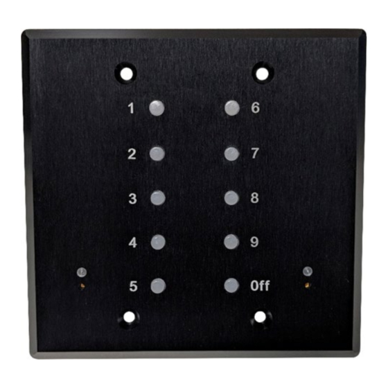
Summary of Contents for Doug Fleenor Design PRE10QUATRO
- Page 1 Model: PRE10QUATRO Operations Manual Doug Fleenor Design, Inc. 396 Corbett Canyon Road Arroyo Grande, CA 93420 (805) 481-9599 Voice and FAX Manual Revision January 2024 Page 1 of 12...
-
Page 2: Product Overview
These features are compatible with the existing PRE10-A and ES2 products. The back of the PRE10QUATRO provides a 2-pin power connection, for use with a doorbell transformer or DC supply, as well as four 3-pin DMX512 connections. The four DMX512 connections are all individually isolated to provide protection to the connected equipment. -
Page 3: Specifications
SPECIFICATIONS Connectors Phoenix Contact MSTB series 3 position, and 2 position, pluggable terminal block 3 Pin Model: MTSB 2,5/3-ST-5,08 (for DMX512) 2 Pin Model: MTSB 2,5/2-ST-5,08 (for Power) Transceivers (4) Isolated EIA-485 receivers with 15KV ESD and ± 42VDC protection (ADM2795) Power Input Input: 9 - 15 Volts (AC or DC), 350mA Environmental... -
Page 4: Option Jumpers
Option Jumpers INSTALLED | REMOVED RECORDING ENABLED | RECORDING DISABLED MAIN/SINGLE STATION | REMOTE STATION RESERVED | RESERVED SINGLE STATION | MULTISTATION NORMAL | TROUBLESHOOT (RX ONLY) RADIO BUTTON MODE | PUSH ON PUSH OFF BUTTON MODE (POPO) JP1 RECORD: Removal prevents the station from writing preset looks and fade times into the internal memory. - Page 5 SYSTEM TOPOLOGY – SINGLE STATION A basic PRE10QUATRO system will operate in single station mode, using only one wall panel. Typical systems will have all configuration jumpers in the ON position, which is how the product is configured from the factory. The DMX512 daisy chain begins at the CONSOLE, and most systems will have the PRE10QUATRO as the next device along the DMX512 daisy chain.
- Page 6 JP4 and JP2 (photos below). The remote station only utilizes the DMX512 MAIN/REMOTE connection on the rear panel. Remotes may be any of the following products: PRE10QUATRO, PRE10-A, and ES2. NOTE Systems with non-compliant DMX512 receivers, such as those that flicker when receiving RDM, may flicker when connected to a system using the MULTISTATION system topology.
-
Page 7: Installation
INSTALLATION PRE10QUATRO installs in a 2-gang wall box. Four screws are included to attach the faceplate to the wall box. Wire connections for POWER and one or more DMX512 connections are required inside the box. The terminal blocks for these connections are... - Page 8 DMX512 Wiring Requirements: Cable suited for RS-485 (or otherwise suitable for DMX512) must be used for all DMX512 connections. DMX512 data cable connects each universe using touch and go wiring on the three pin connectors. Touch and go wiring connects DMX IN and DMX THRU wires using a single connector.
-
Page 9: Setup And Operation
RECORDING PRESETS* To record a preset, the PRE10QUATRO must be connected to one or more DMX512 sources. 1. Using the primary DMX512 console, set a “look” to be recorded. The red LED on the station will illuminate when receiving a signal from the console. - Page 10 Crossfade times range from a minimum of 0 seconds to a maximum of 999 seconds (16 minutes and 39 seconds). Crossfade times cannot be set while the PRE10QUATRO is locked out (red LED is illuminated). Crossfade times cannot be set while the Record Lockout jumper (JP1) is...
-
Page 11: Troubleshooting
(not swapped) between the console and the PRE10QUATRO. If buttons 2, 4, 7, or 9 are illuminated it means the PRE10QUATRO is seeing data on the corresponding connector, but no full frames of DMX512. -
Page 12: Limited Manufacturer's Warranty
Limited Manufacturer's Warranty Products manufactured by Doug Fleenor Design (DFD) carry a five-year parts and labor warranty against manufacturing defects. It is the customer's responsibility to return the product to DFD at the customer's expense. If covered under warranty, DFD will repair the unit and pay for return ground shipping.

Need help?
Do you have a question about the PRE10QUATRO and is the answer not in the manual?
Questions and answers