
Summary of Contents for Quantifi Photonics IQRX EPIQ Series
- Page 1 IQRX High Performance Coherent Optical Receiver EPIQ User Manual quantifiphotonics.com...
- Page 2 Information provided by Quantifi Photonics is believed to be accurate and reliable. However, no responsibility is assumed by Quantifi Photonics for its use nor for any infringements of patents or other rights of third parties that may result from its use. No license is granted by implication or otherwise under any patent rights of Quantifi Photonics.
-
Page 3: Table Of Contents
7.2 Set values 7.3 SET values and ACTUAL values 7.4 Manage CohesionUI settings 7.5 Change the instrument IP address 7.6 View system information 8 Controlling your IQRX with CohesionUI 3 / 80 Quantifi Photonics | IQRX EPIQ User Manual | Version 2.00... - Page 4 10 Controlling your IQRX with SCPI commands 10.1 Programming conventions 10.1.1 Index addressing of modules (slot, source) and units (channel) 10.2 Status and event registers 10.2.1 Standard Event Status Register 4 / 80 Quantifi Photonics | IQRX EPIQ User Manual | Version 2.00...
- Page 5 11.5 SCPI Command Console 12 Working with optical fibers 13 System requirements 14 Maintenance 14.1 Annual calibration schedule 15 Technical Support 15.1 Contacting the Technical Support Group 5 / 80 Quantifi Photonics | IQRX EPIQ User Manual | Version 2.00...
- Page 6 15.2 Transportation 16 Warranty Information 16.1 General information 16.2 Liability 16.3 Exclusions 16.4 Certification 16.5 Service and repairs 6 / 80 Quantifi Photonics | IQRX EPIQ User Manual | Version 2.00...
-
Page 7: What's In This User Manual
Controlling your IQRX with CohesionUI SCPI commands: Controlling your IQRX with SCPI commands Programming applications Touchscreen: Operating the IQRX from the LCD interface Managing your IQRX Upgrade firmware Restore factory settings 7 / 80 Quantifi Photonics | IQRX EPIQ User Manual | Version 2.00... -
Page 8: Conventions
Indicates a potentially hazardous situation which, if not avoided, may result in minor or moderate injury or component damage. Do not proceed unless the required conditions are met and understood. NOTE Indicates relevant information that requires your attention. 8 / 80 Quantifi Photonics | IQRX EPIQ User Manual | Version 2.00... -
Page 9: Safety Information
Do not install or terminate fibers while the light source is active. Turn the Quantifi Photonics product OFF before inspecting the end face(s) of the product, or any optical patch cords connected to it. Never look directly into a live fiber; ensure that your eyes are protected at all times. -
Page 10: Electrostatic Discharge Precautions
Store the unused product in the original protective electrostatic packaging that it was shipped in. Use a wrist strap and grounding table mat when unpacking or handling the product. 10 / 80 Quantifi Photonics | IQRX EPIQ User Manual | Version 2.00... -
Page 11: Introducing The Iqrx - High Performance Coherent Optical Receiver
LabView, C++, Python, or any of the other popular programming languages used to control automatic test equipment (ATE). CohesionUI™ Quantifi Photonics' web-based graphical user interface CohesionUI is hosted on Microsoft Windows® and enables you to control your device from any supported web browser. -
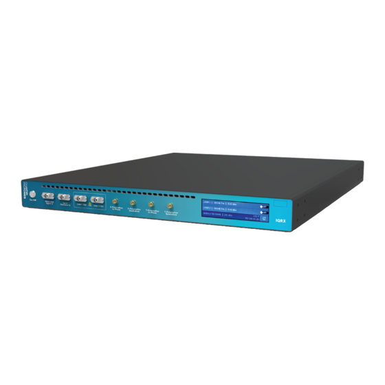
Page 12: Hardware Description
RF signal Y-Pol-Q output LCD touchscreen NOTE You must use the IEC cable that has been supplied by Quantifi Photonics with the unit. 12 / 80 Quantifi Photonics | IQRX EPIQ User Manual | Version 2.00... -
Page 13: Iqrx 1000 Series Schematic Diagram
4.2 IQRX 1000 Series schematic diagram 13 / 80 Quantifi Photonics | IQRX EPIQ User Manual | Version 2.00... -
Page 14: Instrument Ip Address
Change the instrument IP address) Multi-instrument control If you have several Quantifi Photonics instruments with static IP addresses on your network, make sure to assign a unique IP address to each instrument before connecting. For details, refer to Change the instrument IP address 14 / 80 Quantifi Photonics | IQRX EPIQ User Manual | Version 2.00... -
Page 15: Setting Up Hardware
NOTE You must use the IEC cable that Quantifi Photonics supplies with the unit. Please check for the fiber end-face type of the optical ports, such as PC or APC, and only use the same type optical connector to avoid damaging the end-face. -
Page 16: Set Up Your Iqrx Instrument And Power On
After powering ON, please wait at least 1 minute before attempting to communicate with the unit. This gives the unit time to finish boot procedures and initialize the communication server. 16 / 80 Quantifi Photonics | IQRX EPIQ User Manual | Version 2.00... -
Page 17: Rf Electrical Connections
Do not bend or deform the rigid cables, as this will cause damage. Use a torque wrench to control the tightening pressure on all RF connections. 17 / 80 Quantifi Photonics | IQRX EPIQ User Manual | Version 2.00... -
Page 18: Installing Software
6 Installing software To work with Quantifi Photonics MATRIQ and EPIQ instruments, you need to install the latest version of the Cohesion Operator software package on any computer that you use to connect with your IQRX instrument (client computer). For details on system requirements and supported browsers, refer System requirements. -
Page 19: Install The Cohesion Operator Software Package
The installation wizard will install required drivers, applications, and desktop icons on the computer. Multi-instrument control If another Quantifi Photonics instrument is already connected to the client computer via USB, make sure each instrument has a unique USB IP address to avoid any addressing conflicts. For details, refer to Instrument IP address... -
Page 20: Check Firmware Version And Other Information
3. Current instrument information will be displayed. Installed Package refers to the currently loaded firmware version. Alternatively, you can check instrument information in CohesionUI, refer to View system information. 20 / 80 Quantifi Photonics | IQRX EPIQ User Manual | Version 2.00... -
Page 21: Upgrade Firmware
5. In Package, click the Browse button, navigate to the previously downloaded firmware package and select it. 6. Click Upgrade. The instrument will be upgraded to the selected firmware package. This can take a few minutes and the instrument might reboot several times 21 / 80 Quantifi Photonics | IQRX EPIQ User Manual | Version 2.00... - Page 22 If an upgrade attempt is unsuccessful, the Cohesion Operator will stop the upgrade process and restore the instrument to its previous firmware version. Messages will be displayed accordingly. 22 / 80 Quantifi Photonics | IQRX EPIQ User Manual | Version 2.00...
-
Page 23: Restore Factory Settings
This will retrieve instrument information, with Installed Package showing the current firmware version. 4. Click Restore. The instrument will be returned to factory settings, including IP address settings. 23 / 80 Quantifi Photonics | IQRX EPIQ User Manual | Version 2.00... -
Page 24: Cohesionui - Overview
7 CohesionUI - Overview CohesionUI is a web-based graphical interface that you can use to work with your Quantifi Photonics products. CohesionUI is part of the EPIQ firmware package running on your IQRX instrument. From the menu on the left you can navigate to the following pages: 1. -
Page 25: Access Instruments With Cohesionui
7.1 Access instruments with CohesionUI You can open CohesionUI for Quantifi Photonics MATRIQ and EPIQ instruments: from Cohesion Operator, or in a supported browser by entering the instrument IP in the address bar. To open CohesionUI, you need the IP address of the instrument. For details, refer Instrument IP address. - Page 26 To open CohesionUI in a browser: 1. Launch a supported browser (for details refer System requirements). 2. Enter the instrument IP address in the address bar. CohesionUI will launch in the browser. 26 / 80 Quantifi Photonics | IQRX EPIQ User Manual | Version 2.00...
-
Page 27: Set Values
To set a pre-defined value, for example MIN, MAX or DEF: 4. Click on a parameter and select a value from the dropdown menu. 5. Confirm the value. 27 / 80 Quantifi Photonics | IQRX EPIQ User Manual | Version 2.00... -
Page 28: Set Values And Actual Values
: The actual value of the parameter as queried by the product. SET: The intended value of a given parameter as set by the user. For details on how to set values, refer values. 28 / 80 Quantifi Photonics | IQRX EPIQ User Manual | Version 2.00... -
Page 29: Manage Cohesionui Settings
Please note that the units displayed on this page are not always relevant for each product. 3. Step size refers to the amount by which a value is increased or decreased when clicking the + or - button. 29 / 80 Quantifi Photonics | IQRX EPIQ User Manual | Version 2.00... - Page 30 To adjust unit preferences one at a time: 1. Hover over SETTINGS. 2. Select a unit from the dropdown, for example the power unit. 30 / 80 Quantifi Photonics | IQRX EPIQ User Manual | Version 2.00...
-
Page 31: Change The Instrument Ip Address
You can change the instrument's static USB IP address, and assign a static Ethernet IP address if required. Multi-instrument control If you have several Quantifi Photonics instruments with static IP addresses on your network, make sure to assign a unique IP address to each instrument before connecting. - Page 32 To change the Ethernet IP address: 1. Connect with the instrument from a client computer via USB. Ensure that this the only Quantifi Photonics instrument currently connected via USB. 2. Open CohesionUI using the currently assigned USB IP address (for details refer Access instruments with CohesionUI).
-
Page 33: View System Information
1. Refer to the top right corner in CohesionUI. 2. For more details, click INFO to display the information panel. 3. The information panel lists the instrument's serial number, and software and firmware versions. 33 / 80 Quantifi Photonics | IQRX EPIQ User Manual | Version 2.00... -
Page 34: Controlling Your Iqrx With Cohesionui
8 Controlling your IQRX with CohesionUI You can use Quantifi Photonics' graphical user interface CohesionUI to work with your IQRX instrument. For details on how to get started with CohesionUI, refer to CohesionUI - Overview. 8.1 Modulated signal value The measured optical power is shown as MODULATED SIGNAL. -
Page 35: Setting The Laser Source Parameters
POWER: The desired output power of the IQRX instrument. NOTE The tick mark MUST be clicked in order for any changes or values that were entered to be applied successfully. 35 / 80 Quantifi Photonics | IQRX EPIQ User Manual | Version 2.00... -
Page 36: Tuning The Laser Source
1 GHz, then the frequency grid would be as shown in the below image. The general rule for the set of valid frequency GRID points is: 36 / 80 Quantifi Photonics | IQRX EPIQ User Manual | Version 2.00... -
Page 37: Frequency Tuning
In the example below, the user sets the output frequency to 193.414489 THz, with a GRID spacing of 1 GHz. The laser first tunes to the closest GRID point below the intended frequency value (193.414 THz), and then uses FINE TUNE OFFSET to fine tune by 489 MHz up to the final set point. 37 / 80 Quantifi Photonics | IQRX EPIQ User Manual | Version 2.00... -
Page 38: Frequency Fine Tuning
In the example below, the GRID spacing has been set to 20 GHz, meaning that between any two adjacent GRID points, there lies an 8 GHz region that is non-accessible. If tunability is a primary concern, it is suggested that the user set the GRID spacing to be <= 6 GHz. 38 / 80 Quantifi Photonics | IQRX EPIQ User Manual | Version 2.00... - Page 39 39 / 80 Quantifi Photonics | IQRX EPIQ User Manual | Version 2.00...
-
Page 40: Toggling The Laser On/Off
8.4 Toggling the laser on/off To toggle the laser in a specific channel of the IQRX on or off, toggle the STATE ON/OFF button. 40 / 80 Quantifi Photonics | IQRX EPIQ User Manual | Version 2.00... -
Page 41: Downloading The Receiver Calibration Settings File
8.5 Downloading the receiver calibration settings file To download the receiver calibration settings json file, click the DOWNLOAD button. The file will be saved in the Downloads folder in your computer as receiverSettings.json. 41 / 80 Quantifi Photonics | IQRX EPIQ User Manual | Version 2.00... -
Page 42: Operating The Iqrx From The Lcd Interface
The IQRX IP address is displayed irrespective of the operation mode (access over USB or Ethernet). When both USB and Ethernet cables are connected to the instrument, the IP displayed on the LCD will alternate between USB and Ethernet IP addresses. 42 / 80 Quantifi Photonics | IQRX EPIQ User Manual | Version 2.00... -
Page 43: Setting Laser Channel Parameter Values
POWER has been set to the MAX value of 15 dBm. To apply the changes, click the tick mark. NOTE The tick mark MUST be clicked in order for any changes or values that were entered to be applied successfully. 43 / 80 Quantifi Photonics | IQRX EPIQ User Manual | Version 2.00... -
Page 44: Toggling The Laser Channel On / Off
The up and down arrows are used to scroll the selections of the menu when there are more options than can be displayed. The bottom button is used to take a step ‘back’ one level in the menu system. This will return you to the previous menu page. 44 / 80 Quantifi Photonics | IQRX EPIQ User Manual | Version 2.00... -
Page 45: Device Information
To test if the IP addressing has worked, power OFF the instrument, and disconnect the USB cable. Turn the unit back ON, and once it has finished booting, check the IP address shown on the main LCD display. 45 / 80 Quantifi Photonics | IQRX EPIQ User Manual | Version 2.00... -
Page 46: Usb Connectivity Configuration
To access the step size settings, click on the STEP SIZE tab in the menu. Step size refers to the amount by which the wavelength, power and additional values increase or decrease when the + or - button are clicked. 46 / 80 Quantifi Photonics | IQRX EPIQ User Manual | Version 2.00... -
Page 47: Lcd Calibration Reset
To reset the LCD interface settings and calibration, click on the LCD CALIBRATION tab in the menu and select OK. Follow the instructions on the display to calibrate the LCD interface. 47 / 80 Quantifi Photonics | IQRX EPIQ User Manual | Version 2.00... -
Page 48: Controlling Your Iqrx With Scpi Commands
[VALUE1] or [VALUE2] can be used, but not both. Some commands may have more than two choices available. This parameter can be omitted where the command has a default defined in the command description. 48 / 80 Quantifi Photonics | IQRX EPIQ User Manual | Version 2.00... -
Page 49: Index Addressing Of Modules (Slot, Source) And Units (Channel)
Unless specified, all output response data is transmitted in ASCII format. 10.2 Status and event registers 10.2.1 Standard Event Status Register The Standard Event Status Register (SESR) is modified by the Quantifi Photonics product with the results of the command operations. Description 7 (MSB), 6... -
Page 50: Status Byte Register
The Event Status Bit (ESB) is set from the SESR and the SESR Mask Message Available (MAV) is set when there is data in the output queue 3, 2, 1, 0 (LSB) Not used 50 / 80 Quantifi Photonics | IQRX EPIQ User Manual | Version 2.00... -
Page 51: Status And Event Registers Diagram
10.2.5 Status and event registers diagram 51 / 80 Quantifi Photonics | IQRX EPIQ User Manual | Version 2.00... -
Page 52: Command Summary
Command Description :MODULE<n> >> :IDN? Query the module identification >> :OPC? Query the Operation Complete Status of the module >> :OPTions? Query installed modules Summary >> 52 / 80 Quantifi Photonics | IQRX EPIQ User Manual | Version 2.00... -
Page 53: Configuration Commands
Set the fine-tuning laser output frequency >> :GRID? Query the grid spacing >> :GRID Set the channel grid spacing >> :TEMPerature? Get the laser temperature Summary >> 53 / 80 Quantifi Photonics | IQRX EPIQ User Manual | Version 2.00... -
Page 54: Command Descriptions
0: modules installed in the chassis still have commands to execute in the input queue NOTE: Any commands sent to the module when :MODUle<slot>:OPC? is NOT equal 1, may not execute or return an error. Example *OPC? -> 1 54 / 80 Quantifi Photonics | IQRX EPIQ User Manual | Version 2.00... - Page 55 Query the Standard Event Status Enable Register (Mask) Parameters Response Unsigned integer 8 bit value for the register <0 to 255>, as a string. Example *ESE? -> 254 55 / 80 Quantifi Photonics | IQRX EPIQ User Manual | Version 2.00...
-
Page 56: System Commands
Query the number of modules installed in the instrument Parameters Response Returns the number of modules installed in the IQRX Example :SYSTem:MODUles? -> 2 56 / 80 Quantifi Photonics | IQRX EPIQ User Manual | Version 2.00... -
Page 57: Module Commands
Query installed modules Parameters Response A comma separated array, or a single integer value based on the arguments given Example :MODU2:OPTions? -> 1,,,,,,, 57 / 80 Quantifi Photonics | IQRX EPIQ User Manual | Version 2.00... -
Page 58: Configuration Commands
Summary >> Syntax >> :OUTPut<n>:CHANnel[m]:STATE<wsp>[ON|OFF] Description Set the laser output state Parameters ON|OFF: Sets the output state on or off Response Example :OUTP2:CHAN1:STATE ON 58 / 80 Quantifi Photonics | IQRX EPIQ User Manual | Version 2.00... - Page 59 If the laser STATE is ON while setting WAVelength, FREQuency or FREQuency:FINE, there will be a minimal non-stable output generated during the transition to the new value, as the configuration commands are executed. 59 / 80 Quantifi Photonics | IQRX EPIQ User Manual | Version 2.00...
- Page 60 IQRX specifications MIN: Set the minimum programmable value MAX: Set the maximum programmable valuee DEF:Set the default programmable value Response Example :SOUR2:CHAN1:WAV 1550 NM 60 / 80 Quantifi Photonics | IQRX EPIQ User Manual | Version 2.00...
- Page 61 MIN: Set the minimum programmable value MAX: Set the maximum programmable value DEF: Set the default programmable value Response Example :SOUR2:CHAN1:FREQ 1.92 THZ 61 / 80 Quantifi Photonics | IQRX EPIQ User Manual | Version 2.00...
- Page 62 Valid range is from -6 GHz to 6 GHz in 1 MHz increments as detailed in the specifications. MIN: Get the minimum programmable value MAX: Get the maximum programmable value DEF: Get the default programmable value Response Example :SOUR2:CHAN1:FREQ:FINE MAX 62 / 80 Quantifi Photonics | IQRX EPIQ User Manual | Version 2.00...
- Page 63 :SOUR2:CHAN1:GRID 2 GHZ Command :SOURce<n>:CHANnel[m]:TEMPerature? Summary >> Syntax :SOURce<n>:CHANnel[m]:TEMPerature? >> Description Get the laser temperature Parameters Response Numerical temperature in degrees Celsius Example :SOUR2:CHAN1:TEMP? -> 26.88 63 / 80 Quantifi Photonics | IQRX EPIQ User Manual | Version 2.00...
-
Page 64: Programming Examples
#Query the Laser actual power :SOURce2:CHANnel1:FREQuency? #Query the Laser set frequency #Querying the Signal input power from the Power module :SENSe1:SIGnal? #Query the optical input power 64 / 80 Quantifi Photonics | IQRX EPIQ User Manual | Version 2.00... -
Page 65: Programming Applications
In NI-MAX a RIO interface will show up, however there are no communication methods available or implemented on this interface. Quantifi Photonics products are ONLY accessible through the VISA TCPIP INSTR interface provided by the CohesionSCPI service installed on the system. -
Page 66: Setting Up Ni-Max Application
3. Select Manual Entry of LAN Instrument. Enter in the Hostname or IP Address. Note when operating locally, enter in the localhost IP address of 127.0.0.1. Click Finish to end the setup process. 66 / 80 Quantifi Photonics | IQRX EPIQ User Manual | Version 2.00... -
Page 67: Setting Up Ni-Visa Application
2. On the right-hand side panel, select Open VISA Test Panel. A new window will popup. Click the Input / Output button from the window menu. Valid chassis and module commands can be entered in, and their returns queried 67 / 80 Quantifi Photonics | IQRX EPIQ User Manual | Version 2.00... -
Page 68: Python® 2.7 Code Example
11.3 Python® 2.7 code example The following example shows how to communicate with the Quantifi Photonics product using Python code. # You can get VXI11 from pip: # pip install python-vxi11==0.9 import vxi11 from vxi11.vxi11 import Vxi11Exception # replace this with the IP of your device ip = "127.0.0.1"... -
Page 69: Matlab® Code Example
11.4 MATLAB® code example To communicate with the Quantifi Photonics product in MATLAB® the installation of a VISA IO driver is required. These drivers enable the creation of the Interface Object for instrument communication. If developing locally on the EPIQ Platform, then these will already be installed. However, if development is on a remotely connected system the VISA Libraries, e.g. -
Page 70: Scpi Command Console
11.5 SCPI Command Console The SCPI Command Console enables you to communicate with Quantifi Photonics devices via SCPI commands. You can easily test commands and verify their syntax. For available SCPI commands, refer to the user manual of the Quantifi Photonics device you are communicating with. - Page 71 2. To switch to another Quantifi Photonics device: Enter ip and press <ENTER>. Enter the IP address of the Quantifi Photonics product you would like to switch to and press <ENTER>. Confirm that you are communicating with the right product: Enter *idn? and press <ENTER>.
- Page 72 The instrument executes the command, there will be no action response. 8. If you enter a command incorrectly, for example: *csl The instrument returns error code 17: IO write error. 72 / 80 Quantifi Photonics | IQRX EPIQ User Manual | Version 2.00...
-
Page 73: Working With Optical Fibers
Always inspect fiber end faces for cleanliness using a fiber inspection probe before inserting them into a port.. If required, clean fibers and faces as detailed below. Quantifi Photonics is not responsible for damage or errors caused by bad fiber cleaning or handling. NOTE To avoid damaging ferrules or fiber faces due to mismatched connectors, always check ports and connector type information before inserting a connector. - Page 74 If your connector features a screw sleeve, tighten the connector to firmly maintain the fiber in place. Do not over-tighten, as this will dam- age the fiber and the port bulkhead. NOTE Failing to align and/or connect fiber-optic cables properly will result in significant signal loss and reflection. 74 / 80 Quantifi Photonics | IQRX EPIQ User Manual | Version 2.00...
-
Page 75: System Requirements
Microsoft Windows® 10 (64-bit) Quantifi Photonics MATRIQ / EPIQ instruments Google Chrome™ Supported browsers for working with CohesionUI Microsoft Edge® Recommended client computer operating system Microsoft Windows® 10 (64-bit) 75 / 80 Quantifi Photonics | IQRX EPIQ User Manual | Version 2.00... -
Page 76: Maintenance
All Quantifi Photonics products are calibrated during manufacture, and each product is shipped to the customer with a Calibration Certificate. On this certificate, the calibration date, as well as the next calibration due date are mentioned. -
Page 77: Technical Support
15 Technical Support 15.1 Contacting the Technical Support Group To obtain after-sales service or technical support for this product, contact Quantifi Photonics: support@quantifiphotonics.com To accelerate the process, please provide information such as the name and the serial number (see the product identification label), as well as a description of your problem. -
Page 78: Warranty Information
16.2 Liability Quantifi Photonics shall not be liable for damages resulting from the use of the product, nor shall be responsible for any failure in the performance of other items to which theproduct is connected or the operation of any system of which the product may be a part. -
Page 79: Certification
Quantifi Photonics. 16.4 Certification Quantifi Photonics certifies that this equipment met its published specifications at the time of shipment from the factory. 16.5 Service and repairs To send any equipment for service, repair or calibration please contact the Technical Support Group: support@quantifiphotonics.com. - Page 80 Measure. Solve. Quantifi Photonics is transforming the world of photonics test and measurement. Our portfolio of optical and electrical test instruments is rapidly expanding to meet the needs of engineers and scientists around the globe. From enabling ground- breaking experiments to driving highly efficient production testing, you'll find us working with customers to solve complex problems with optimal solutions.
Need help?
Do you have a question about the IQRX EPIQ Series and is the answer not in the manual?
Questions and answers