
Related Manuals for Incon Auto-Learn TS-LS300

Summary of Contents for Incon Auto-Learn TS-LS300
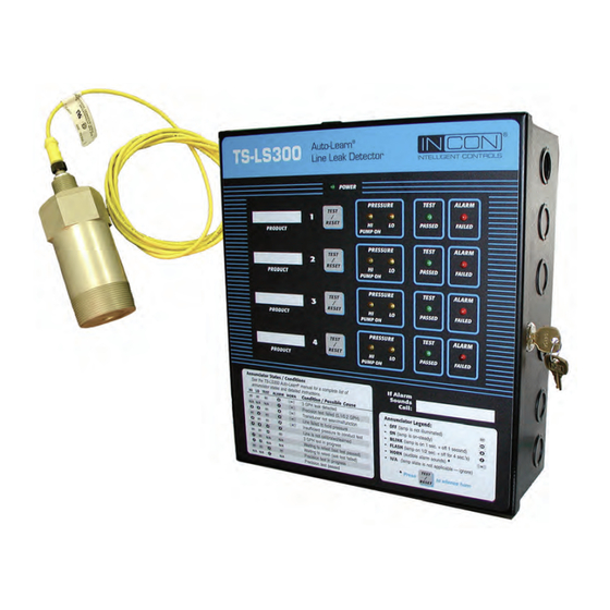
- Page 1 User’s ® TS-LS300 Auto-Learn Guide Pressure-Based Electronic Line Leak Detector System Part Number: 000-0140 Rev. D Copyright March 2012 ©...
- Page 2 NOTICE INCON has strived to produce the finest possible manual for you, and to ensure that the information contained in it is complete and accurate. However, INCON makes no expressed or implied warranty with regard to its contents. INCON assumes no liability for errors or omissions, or for any damages, direct or consequential, that result from the use of this document or the equipment which it describes.
-
Page 3: Table Of Contents
Table of Contents Preface ......................P-1 Safety ....................... 1-1 Mechanical Installation ..................2-1 Electrical Installation & Wiring ................. 3-1 Line Calibration ....................4-1 LS300 Console Operation ................5-1 TS-LS300 Troubleshooting guide ..............6-1 Appendix A Specifications ................. A-1 TABLE OF CONTENT Page TOC-1 LS300 User’s Guide... -
Page 4: Preface
Read and follow the entire instructions in this manual before installing or working on this equipment. NOTE Certified Installer/Service Person: Only an INCON certified installer or service person is allowed to access both the user interface kepad and areas internal to the TS-LS300 console. - Page 5 General Overview The TS-LS300 Auto-Learn Line Leak Detector (LLD) is a precision electronic line-leak-detection ® system that is produced for installation in a petroleum pumping system. The Auto-Learn Line Leak Detector automatically monitors at certain times and will indicate pipeline leaks should a leak occur. An alarm indicator lights, an audible alarm horn sounds, and positive pump shutdown happens when a leak is detected.
- Page 6 Each product line must be precision tested and verified free of leaks before any component of the LS300 system is installed. After verification, the LS300 Auto-Learn ® system is installed, wired, and calibrated. The supplied leak-generating device/calibration kit* is attached to a needle valve, and the appropriate line channel selector switch is placed in the learn position at the console.
- Page 7 Two LS300 Auto-Learn consoles for line leak detection of up to 8 lines: one console has the TS-TPI interface circuit board for connection to the other LS300 console via a special RS-232 cable and connects to the INCON ATG console via RS-485 communication for LLD interface and for Turbine Pump Controller control...
- Page 8 TS-LS300 TS-LS300 TS-ATG Auto-Learn Auto-Learn Console Console Console Inputs (#1-4): Inputs (#1-4): Lines (#) Lines (#) TS-TPI Hooks (#) Hooks (#) RS485 Power Power TS-LS300 TS-ATG Auto-Learn Console Console Inputs (#1-4): Lines (#) TS-TPI Hooks (#) RS485 Power TPC TPC TPC TPC TS-LS300 TS-LS300...
- Page 9 the use of Auto-Learn in rigid pipelines up to 163-gallon capacity and in flex pipelines up to 39.5 gallons. TABLE P-2 Third Party Approved — Max Pipe Lengths: 1" 1 1/2" 1 3/4" 2" 2 1/2" 3" 4" 5" Pipe Diameter I.D. (25 mm) (38 mm) (44 mm)
- Page 10 Petroleum absorbent and absorbent rags, and approved waste containers Gasoline/oil resistant, non-hardening, UL Classified, Pipe Dope / Thread Sealant (Gasoila) to seal threads of the LSU300 transducer & Needle Valve Kit Single scale, general purpose, Pressure Gauge (1/4 inch NPT, 0 to 60 psi in 1 psi increments) for temporary installation during site assessment and during the LS300 Auto-Learn calibration step Approved Gasoline/fuel oil container test tank (minimum 5-gallon capacity) to...
-
Page 11: Safety
SAFETY Safety First – Before Working on this Equipment CAUTION This equipment is designed to be installed in association with volatile hydrocarbon liquids such as gasoline and diesel fuel. Installing or working on this equipment means working in an environment in which these highly flammable liquids or vapors are present. - Page 12 (an environmental hazard associated with costly clean-ups), and fire or explosion hazard that may result in injury or death. Multiple INCON Danger stickers are supplied with electronic line NOTE leak detectors. Apply these stickers on the pump relay box...
- Page 13 Codes. CAUTION Although the LSU300 is water resistant, INCON does not recommend operating the LSU for long periods while under water. Drain the sump and manhole immediately into a holding tank for disposal per Codes.
- Page 14 CAUTION Petroleum is carcinogenic – use adequate protection to avoid health hazards. ALWAYS cleanup and dispose of used absorbent/rags and petroleum resistant gloves in approved waste containers. Cleanup refuse and dispose of these immediately to avoid personnel injury from vapors or direct skin contact to also avoid possible fire or environmental safety hazards.
-
Page 15: Mechanical Installation
Mechanical Installation Mechanical Installation Sequence: Follow the instructions here to mount the LS300 Auto-Learn console and to install the LSU300 Leak Sensing Unit transducers, and Needle Valves at each STP containment sump (see Figure 2.2 for typical finished installation). Be sure to ask the electrician to do any “electrical” type of work when appropriate. - Page 16 • BEFORE performing any installation or service — turn off/ lock out electrical power sources to the submersible pump(s), and relieve fuel-line pressure. INCON PN 240-1175 Rev. D Page 2-2 MECHANICAL INSTALLATION LS300 User’s Guide...
- Page 17 1.50 7.00 (178 mm) (38mm) TYP. 0.31 (8 mm) THRU MOUNTING HOLES TYP. FOUR PLACES 13.38 (340 HINGE SIDE of 12.75 CONSOLE DOOR (324 11.00 x 12.00 (280 x 305 mm) 11.75 (298 CONSOLE DEPTH 4.00 (102 MM) 0.31 (8 mm) 1.00 TYP.
- Page 18 2-3/8 INCHES 3/4 INCH (69.85 mm) ACROSS (DN20NPT) FLATS 6.25 LSU300 5.13 INCHES Leak INCHES (158.75 Sensing (130.18 Unit NEEDLE VALVE Transducer ACCESSORY (UNASSEMBLED) REF: 020-1029 1 REQ'D AT EACH STP HOUSING 2 INCH NPT (DN50 NPT) (NEEDLE See Figures VALVE KIT) @ 3-2 and 3-3 LINE PRESSURE...
-
Page 19: Electrical Installation & Wiring
Electrical Installation & Wiring Electrical Installation & Wiring Sequence: Basic Installation & Wiring TS-LS300 Auto-Learn Follow the instructions here to wire the LS300 Auto-Learn console, the Console Inputs (#1-4): LSU300 Transducers from each STP containment sump, the Dispenser Lines (#) Hook Inputs, and Console Power Input. - Page 20 LSU300 Transducers TS-LS300 Auto-Learn TS ATG Line Leak Detector Console LS300 Dispenser AutoLearn Hooks Console Input Annunciator States/Conditions Annunciator Legend Power Optional TS-TPI to FE Petro Models: SCI & VFC4 RS232 Comm Console Turbine Pump Controllers (TPC) Port NON-HAZARDOUS AREA HAZARDOUS AREA CLASS 1, DIVISION 1, GROUP C &...
- Page 21 Wire Intrinsically Safe LSU300 transducers only to NOTE TS-LS300 version consoles in conduit apart from non-intrinsically safe wiring. DO NOT run intrinsically safe wiring in the same conduit with non- intrinsically safe wiring. Auto-Learn TS-LS300 Line Leak Detector INTELLIGENT CONTROLS POWER LS300 Auto-Learn PRESSURE...
- Page 22 NOTE Wire Explosion Proof LSU300E transducers only to TS-LS300E consoles in accordance with applicable standards. Explosion proof J-Boxes and conduit fittings must be used in this application in hazardous locations. This wiring does not require separation from other non- intrinsically safe wiring. This method can be used for retrofit installations where separate conduit is not available.
- Page 23 Basic Installation & Wiring – all Applications (Continued... ) Remove a portion of the cable jacket (service-loop) inside the J-Box, and install the no-strip electrical connectors inside the J-Box (see Figures 3-2 & 3-3). Verify that all connections are correct and that the like colored and unstripped wires are fully inserted into the no-splice connectors (RED to RED, WHITE to WHITE, BLACK TO BLACK, and SHIELD DRAIN to SHIELD DRAIN) and are spliced together...
- Page 24 Basic Installation & Wiring (Continued... ) Wire Dispenser Hooks (switches) to the Hooks terminals inside the LS300 console, see Figure 3-4. Follow these associations accurately when wiring. Hook 1 must operate the STP at Tank/Line 1, Hook 2 for Tank/Line 2, Hook 3 for Tank/Line 3, Hook 4 for Tank/Line 4.
- Page 25 Basic Installation & Wiring (Continued... ) Wire Console Power to the Power Input terminals inside the LS300 console (see Figure 3-4): Install / use a 10 ampere Circuit Breaker at the Electrical Power Panel that is dedicated/and used only for the LS300 Console(s).
- Page 26 Ground Stud: The installer is to connect the Earth Ground Conductor to the most convenient ground terminal as long as it meets local and national codes. If the ground stud is to be used the installer shall follow the proper stacking configuration shown in figure 3-5. The earth ground conductor must be 12 AWG or larger.
-
Page 27: Line Calibration
Line Calibration NOTE ! Before Calibrating a Line: A PRECISION LINE TEST MUST BE CONDUCTED on each line before installing the LS300 Auto- Learn LLD system for the first time, or before replacing, or before adding a new LSU300 LLD ®... - Page 28 Line Calibration Steps Steps to Install the Leak Generator Device {Calibration Kit} NOTE The Leak Generator Device can be installed during the Mechanical Installation of the needle valve, See chaper 2. Disconnect power, Lock out and Tag the electrical circuit breakers to the submersible pump, dispensers and related devices at the electrical supply box associated with the product line to be worked on.
- Page 29 LS300 CALIBRATION KIT ABOUT 72 INCHES (182.88 cm) LONG PRESSURE REF: 020-0315 GAUGE 1 REQUIRED PER SYSTEM LEAK GENERATOR CALIBRATION KIT AT STP (NEEDLE VALVE) ...ONLY ONE LINE IS CALIBRATED AT A TIME DURING LS300 AUTO-LEARN MODE Figure 4-1 Leak Generator Device {Calibration Kit} & Pressure Gauge at STP If not done in chapter 3, Wire the dispenser hook signal to the proper channel associated with the product line being worked on (Figure 4-2).
- Page 30 Run/Stop Transducer Switch Terminal Blocks Learn/Detect Switches White Black Shield Channel Hook Enable Terminal Switch Blocks Up-Enable Hook In: From Down- Disable dispenser Hook Out: To Pump Controller Input Power L2 (or N) Ground Ground Fuse F1 (Hook Input Circuits) Input Voltage Fuse F2 (Over-current protection) Selector...
- Page 31 are any leaks, immediately turn off the power at the load center, lock out and tag out breakers, and repair the leaks before proceeding. When making changes to the switch settings, LEARN/DETECT or CHANNEL NOTE ENABLE switches, the STOP/RUN switch must be moved to the STOP position for ten seconds, after the switch changes are completed, before the changes will take effect and returning the console to RUN.
- Page 32 WARNING Prevent Static electric sparks and possible explosion by placing container on ground. Always have container on the ground when filling with gasoline. Use only containers approved for motor fuel storage. 11.) Switch the STOP/RUN switch to STOP (Figure 4-3). See Figure 4-2 for switch location. 12.) Verify Mode Select Switch for this channel is in the LEARN position (Figure 4-4).
- Page 33 Support at (800) 984-6266 for any other concerns or questions regarding ® installation or service of the LS300 Auto-Learn system. For installation instructions for connecting the TS-LS300 console to an Incon tank gauge, please refer to the TS-TPI Programming User’s Guide. LINE CALIBRATION (LEARN MODE) Page 4-7...
-
Page 34: Ls300 Console Operation
LS300 Console Operation Line Leak Tests For normal operation verify the following: At the LS300 Auto-Learn® Console: For each channel in use the corresponding channel enable switch is in the ON position. The Mode Select switch, for each channel in use, is set in the DETECT position. The “STOP/RUN” switch is in the RUN position. - Page 35 Annual (0.1 GPH) Leak Test When the line has been inactive for 6 hours, an annual (0.1 GPH) test is initiated. This test will be performed every 5 minutes until a test has passed. If there are three consecutive failures, with no passes, the ALARM light will flash, and the HORN will sound, indicating that there is a precision leak in the system.
- Page 36 required to complete the monthly (0.2 GPH) test. In between these tests, lamps will indicate whether the last test passed or failed. A PASS will be indicated by a single flash on the Test indicator lamp. Three consecutive FAILURES will put Auto-Learn in alarm condition.
- Page 37 Detected Leaks When a line leak is detected, you the owner/authorized representative must follow the steps outlined below: Record (log) and identify: the type of leak test that failed (Gross test, Monthly test, or an annual line leak test), the time it failed, the date, the product line number, and the product-name.
- Page 38 Compliance is determined by local/State / Federal Laws and Regulations. Non-compliance may cause site shut-down, fines, or legal action. The TS-TPI Turbine Pump Interface can also be wired to INCON TS-1001/TS- 2001automatic tank gauges (and other future models as developed), which could provide all Tank and Line leak test Compliance Data automatically on a programmed schedule to modems/fax machines at remote sites.
-
Page 39: Ts-Ls300 Troubleshooting Guide
TS-LS300 Troubleshooting Guide Transducer Troubleshooting The transducer is one of the main components of the LS300 Auto-Learn system. This section is to aid in the proper troubleshooting of the transducer and its wiring. A loose or broken wire connection, or damaged insulation on a wire, can cause the transducer to give erratic voltage readings. - Page 40 Run Stop Test Point Switch Locations Figure 6-2 Test Point locations 2. With an ohmmeter, test for shorts between the three transducer wires, and each wire to chassis ground. If a short is Transducer Power to Signal from found, test the connection between the Channel Transducer Transducer...
- Page 41 signal terminal block locations). The resistance should read about 2k ohms, if not contact Technical Support (800)-984-6266. Measure resistance from power test points to the “+V” terminal on each channel (i.e. JP1 to channel 1 “+V” terminal block). The resistance should read about 180 ohms. If it does not, contact Technical Support.
- Page 42 Learn Mode (Calibration) Troubleshooting Horn ON Audible Lamp Indicators Conditions and Possible Causes Alarm TEST ALARM HORN Transducer not seen Mis-wired transducer or Mis-wired Auto-Learn console ® Transducer failure Horn OFF -- Learning Process Learning Transducer Zero PSI - First step in Auto-Learn process Learning Pump ON Pressure - Second step in Auto-Learn process Learning Test Parameters...
- Page 43 Detect Mode (Operation) Troubleshooting Horn ON Audible Lamp Indicators Conditions and Possible Causes Alarm TEST ALARM HORN Gross (3 gph) Leak Alarm - Leak in the system - Leak in the check valve - Leak in the manual pressure relief Monthy or Annual Precision Test Failed - Monthly (0.2 gph) test failed - one flash - Annual (0.1 gph) test failed - two flashes...
- Page 44 (see Warranty Registration form). Accurately fill-in the Warranty Registration Form, on the facing page, photocopy and FAX it to INCON after the system is installed and lines are calibrated and are operational. Installer/Service Provider: Keep the photocopy for your records for future reference, and leave the original filled-in Warranty Registration Form in the manual for future service reference or use during future installations.
- Page 45 LS300 System: Warranty Registration Form Use a medium-point, black ink pen and fill-in the blank data below, photocopy the form, and FAX it to INCON Technical Service: FAX # 1-207-282-9002 (Telephone # 1-800-984-6266). LS300 Warranty Registration Form Console (CU) Model No. LS300 LS300E (Expl.Proof)
- Page 46 Appendix A LS300 Auto-Learn Line Leak Detector ® Technical Specifications Auto-Learn Console ® Alarm Annunciation: Specifications Piezoelectric 90 Db audio output at 10 cm and activates under the following alarm conditions: Models: LS300 (I.S.) & LS300E (ExP) • after a Gross Leak Test fails (3 gph/11 lph), •...
-
Page 47: Appendix A Specifications
Auto-Learn Console Pressure Transducer ® Specifications Specifications Mechanical Specifications Stability: 0.25% FS over full operating temperature Inches & ( mm): Enclosure 11.75H x 10.75L x 3.75D Materials Used: (298H x 273L x 95D) Housing = Anodized Aluminum Encl. w/ Door 12H x 11L x 4D Pressure Transducer (wetted portions) = 17-4 (305H x 279L x 102D) - Page 48 Main PC Board (Explosion Proof version) for LS300E consoles & LSU300E Explosion Proof Transducers only TPI PC Board Contact INCON for Order Numbers for the Replacement Parts Spare LS300 System Parts Spare I.S. Transducer – TS-LSU300 Spare Explosion Proof Transducer – TS-LSU300E for TS-LS300E Exp.Proof consoles only Spare Leak Generating Device/Calibration Kit –...
- Page 49 AUTO-LEARN CONTROL DRAWING INCON PN: 000-1716 Rev. H Page A-4 APPENDIX A LS300 User’s Guide...
- Page 50 AUTO-LEARN CONTROL DRAWING INCON PN: 000-1717 Rev. D APPENDIX A Page A-5 LS300 User’s Guide...
- Page 51 Form to record monthly LS300 status If the LS300 is not connected to a printer through a TS-1001 / TS-2001 Date Time of Line # Precision test Push Test / Reset*** Alarm Indications** Passed?* Y or N Monthly Annual * Monthly (.2 GPH) test passed indicated by single TEST lamp FLASH. Annual (.1 GPH) test passed indicated by double TEST lamp FLASH.
- Page 52 PO BOX 638 SACO ME 04072 TS-LS300 Auto-Learn ® Line Leak Detector User’s Guide...
Need help?
Do you have a question about the Auto-Learn TS-LS300 and is the answer not in the manual?
Questions and answers