Advertisement
Quick Links
Advertisement

Summary of Contents for Spectronik ECO MARATHON PRESSURE REGULATOR
- Page 1 ECO MARATHON PRESSURE REGULATOR EMPR USER GUIDE VERSION 1.0 NOVEMBER 2023...
-
Page 2: Safety, Handling & Support
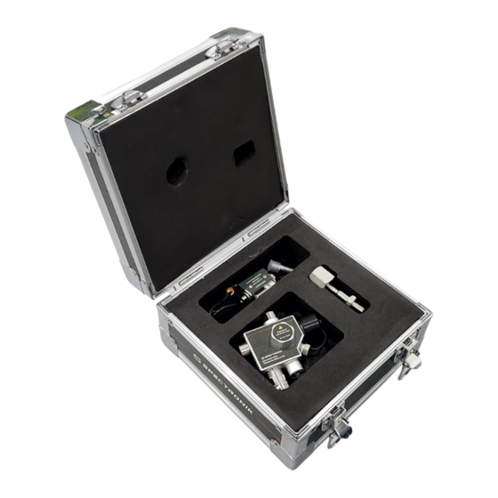
Failure to follow these safety instructions could result in gas leakage, injuries, damage WARNING: to the Eco Marathon Pressure Regulator (EMPR) or other property. Read all the safety information below before using EMPR. Handling Handle EMPR with care. EMPR is not designed for extreme conditions, rough handling, vibration, shock or drop. - Page 3 OVERVIEW 1.1 Eco Marathon Pressure Regulator Eco Marathon Pressure Regulator (EMPR) is specially designed for teams taking part in the Hydrogen prototype and urban category Shell Eco Marathon competitions, with in-built smart and safety features including: Two-stage pressure regulation with factory preset outlet: Inlet up to 350bar and outlet of 0.5bar ▪...
- Page 4 1.3 EMPR Overview Right View Left View Top View Back View Front View CHAPTER 1 | OVERVIEW...
- Page 5 1.4 Features And Function Feature Function Manual On/Off Valve ▪ Open/close the regulator using 5mm Allen Hex key ▪ To connect to refueling hose for gas refilling Refueling Port ▪ In-built one-directional safety valve Emergency Relief Port ▪ For venting of gas in the event of mechanical failure ▪...
- Page 6 1.4 Features And Function Feature Function Thermal Pressure Relief ▪ To vent gas pressure in the cylinder in the event of fire Device (TPRD) ▪ Activated at 110 ▪ To connect EMPR to gas cylinder thread M18 x 1.5 Connection to gas cylinder ▪...
- Page 7 1.5 Dimensions Dimensions in mm 127.80 129.41 139.20 64.60 CHAPTER 1 | OVERVIEW...
-
Page 8: Specifications
SPECIFICATIONS 2.1 Eco Marathon Pressure Regulator Gas media Hydrogen, Nitrogen Rated inlet pressure 350bar (35MPa) Gas outlet pressure (@ rated flow) 0.45-0.75bar (factory set during order) Max outlet pressure (@ zero flow) Gas outlet pressure + 0.3bar Low pressure safety relief valve... - Page 9 2.3 Schematic Diagram Refueling port Low pressure outlet Refueling Line Filter (10µ) Safety Relief Valve Refueling One-way Valve Second Stage Regulator First Stage Regulator TPRD Gas Inlet Filter (10µ) On/Off Valve Gas Pressure Transducer Socket Emergency Relief Valve CHAPTER 2 | SPECIFICATIONS...
- Page 10 The NC Solenoid Valve has an embedded Spike-&-Hold driver to reduce the holding voltage to 3.3VDC after the initial 12VDC to turn on the valve. This allows minimum power consumption of 350mW. User can change to other solenoid valves, such as Spectronik’s Highflow Miniature Valve Module, ▪ for other applications which require higher flowrate.
- Page 11 3.3 2-Wire Operation OFF: H2 Detector: Red/Yellow (Floating) H2 Detector Black +12V Red/Yellow +12V Red/Yellow Black Black 3.4 3-Wire Operation OFF: +12V +12V (Floating) Yellow Yellow Black Black +12V +3.3V-12V Yellow Black H2 Detector: +12V H2 Detector Yellow Black Inverter Signal (3.3V-12V Signal) CHAPTER 3 | OPERATING PROCEDURES...
-
Page 12: Gas Pressure Transducer
GAS PRESSURE TRANSDUCER Features and Applications • Stainless steel 316 body • Welded configuration without sealing o-rings • 10-90% proportional voltage output • Voltage reversal protection • Hydrogen gas pressure measurement • Hydraulic system pressure measurement Technical Specifications • Pressure range: 0-50 MPaG •... - Page 13 Notes • Ensure that all system connections are secure and leak free. Hydrogen leakage may cause fire or explosion in extreme cases. • If the pressure port of the transducer is blocked by a foreign object, do not use a sharp tool to clear the passage.
- Page 14 OPERATING PROCEDURES 5.1 Setting Up EMPR Visually check EMPR for obvious cracks or other physical damage. Warning: never use a faulty regulator. 2. Prepare the necessary wiring of the Gas pressure transducer (B) by following the wiring diagram in Section 4. Keep the pressure transducer port sealing plug in the flight/storage case to prevent losing it.
- Page 15 5.2 Filling the Gas Cylinder Connect the Refueling Adapter (H) to the Refueling Pressure Gauge (F) via the Stainless Steel Refueling Hose (G). Then, connect the Refueling Adapter to the EMPR’s Refueling Port (2). 2. The Refueling Pressure Gauge has a NPT ¼ female port to receive your incoming Hydrogen source.
- Page 16 5.3 Using The Filled Gas Cylinder Connect your gas tubing to the Low pressure gas outlet connector (8) of the NC Solenoid Valve. 2. Activate the NC Solenoid Valve by giving it an ON signal. Gas will now flow out of the low pressure outlet.


Need help?
Do you have a question about the ECO MARATHON PRESSURE REGULATOR and is the answer not in the manual?
Questions and answers