
Summary of Contents for Dixie MSI WETFIT SAFE-Weight
- Page 1 Technical Manual SAFE-Weight 3” 3:16 Plug Valve MSI – A Division of Dixie Iron Works, Ltd. 300 W. Main St. Alice, TX 78332 www.diwmsi.com (800) 242-0059...
-
Page 2: Table Of Contents
TABLE OF CONTENTS WARNING: SECTION 1 GENERAL DESCRIPTION SECTION 2 PARTS SECTION 3 TOOLS SECTION 4 DISASSEMBLY SECTION 5 INSPECTION SECTION 6 ASSEMBLY SECTION 7 MAINTENANCE Revision A 9/15/2023... -
Page 3: Warning
WARNING: This equipment is intended for use in high-pressure and high flow well service applications. High pressure equipment, if not used and maintained properly, can cause serious injury or death and damage to equipment and property. Only operate the valve in the full open or full close position, never flow through the valve in a partially open state as severe erosion may occur and create a hazardous situation. -
Page 4: Section 1 General Description
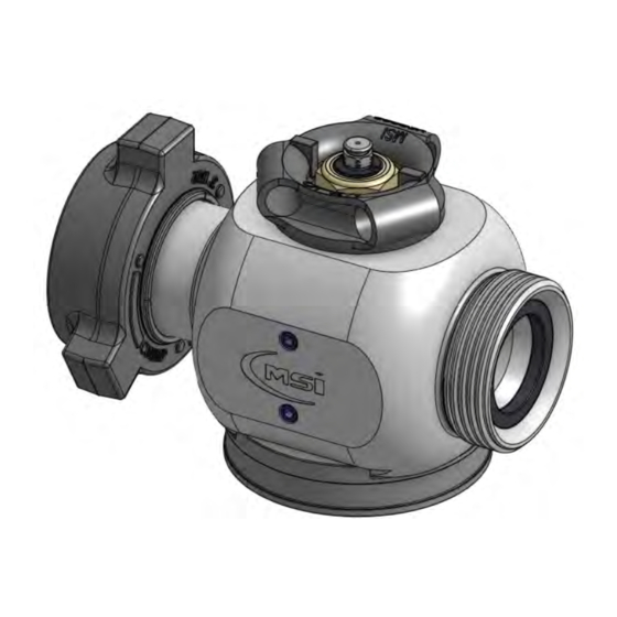
SECTION 1 GENERAL DESCRIPTION The MSI model 3:16 is a quarter turn plug valve intended for the control of high pressure fluids. It is normally provided with a handle adapter for operating with a valve bar but can also be provided with hydraulic, pneumatic, or gear-assisted actuators. -
Page 5: Section 2 Parts
SECTION 2 PARTS Revision A 9/15/2023... -
Page 6: Section 3 Tools
SECTION 3 TOOLS Recommended tools: 1. female end seat tool 2. male end seat tool 3. 3 or 4 lb sledge hammer 4. torque wrench rated for at least 250 ft-lbs 5. 1/2” hex bit 6. 1/2” hex key 7. 5/16” hex key 8. -
Page 7: Section 4 Disassembly
SECTION 4 DISASSEMBLY 1. Prepare a work area and tools for maintenance. A sturdy table with a 3”1502 female union secured to it is helpful. 2. Remove both plugs from one side of the valve using the 5/16” hex key. Revision A 9/15/2023... - Page 8 3. Attach the STA0008 service tool to the side of the valve using the 1/2” hex key. Tighten screws to 230 ft-lb. 4. Lift the valve using a LSA0003 lift sub and attach to the work table with the STA0008 adapter. Revision A 9/15/2023...
- Page 9 5. Rotate valve so that the handle is facing up and tighten the STA0008 wingnut to prevent rotation. Use the 2 3/16” socket to remove the lock nut. Once the locknut and handle have been removed loosen the wingnut and rotate the valve so that the cap is facing up. Retighten the wingnut. 6.
- Page 10 7. Next remove all 8 screws using the 1/2” hex key. 8. Insert 2 of the screws into the tapped holes of the cap and alternate turning them CW (clockwise) until the cap is lifted off of the valve body. 9.
- Page 11 11. Once the plug has been pushed partially out, grasp it using the bore and pull straight out in one continuous motion. 12. Set the plug aside, being careful not to damage the larger cylindrical surface, assuming you are reusing the plug. Use the pick to remove the plug seal from each end, discard the seals and backup rings.
-
Page 12: Section 5 Inspection
SECTION 5 INSPECTION Metallic parts may be reused pending they are in good condition. The following photographs detail critical areas where corrosion, pitting, or scratches may render the part unusable. Clean the following areas thoroughly then inspect. If parts are damaged they should be replaced. BODY Cap seal bore [top arrow], both seat seal faces [middle arrow] and plug seal face [bottom arrow]. - Page 13 SEATS Front face and seal groove. Revision A 9/15/2023...
- Page 14 Back face. Seal groove [right arrow] and inspect keys [left arrow] for dings. If the keys are dinged they should be dressed with a file. Revision A 9/15/2023...
- Page 15 Revision A 9/15/2023...
-
Page 16: Section 6 Assembly
SECTION 6 ASSEMBLY NOTE: It is important that the workstation being used to assemble the valve is clean and free of any foreign materials that could possibly contaminate the parts. Do not sand or deburr near the workstation. 1. Support the valve body with the STA0008 service tool adapter. Make sure that the seat pockets [middle arrow], plug seal face [bottom arrow], and cap seal bore [top arrow] are clean and free of contaminants. - Page 17 4. Lower the seat into the valve cavity with the “ears” up and down. Revision A 9/15/2023...
- Page 18 5. Rock the seat ear to ear as you push it fully into the seat pocket. The seat should be in this approximate position when it is fully seated. 6. Now rotate the seat by hand until it is aligned with the valve cavity. Adjust the seat rotation until the standoff is even on both sides of the seat [blue arrows].
- Page 19 9. Press the seals onto each end of the plug being sure they are firmly seated. There should be enough grease present to keep the bottom seal from falling off. 10. Before continuing to the next step check alignment on both seats one last time and adjust if needed.
- Page 20 12. While keeping the plug aligned, firmly push it down until it is fully inserted into the valve cavity. 13. Rotate the plug to approximately halfway between the open and close position. There is an indicating slot on both ends of the plug that align with the flow bore. Note in the photo below the plug orientation to the end connections.
- Page 21 14. Place the seal backup ring onto the cap and push to the bottom of the groove. One side of the backup ring is cupped and should face the seal, but installing it in either direction is acceptable. 15. Apply a light coat of plug valve grease on the cap seal then place it into the groove on top of the backup ring.
- Page 22 16. Place the cap on the valve such that the screw holes and keys are aligned with those on the valve body. It does not matter which direction the cap goes on otherwise. 17. Apply a light coat of copper anti-seize to the screw threads. Use just enough to coat but not bury the threads.
- Page 23 18. Insert 2 of the screws into opposing holes on the key side of the cap. 19. Using a 1/2” hex wrench or socket, alternate tightening these 2 screws to gradually bring the cap into full level engagement with the valve body. Do not use power tools for this step. Revision A 9/15/2023...
- Page 24 20. Once the cap is fully lowered and against the valve body face install the remaining 6 screws and tighten with hex key until fully engaged. Then use a torque wrench set to 230 ft-lbs to tighten all 8 screws in a cross pattern as shown below. 21.
- Page 25 22. Rotate the valve so that the cap is down then install the handle. Make certain that the slots on the plug align with the indicators on the handle. Rotate the plug to the open position. 23. Replace the lock nut and tighten to approximately 100 ft-lbs with a 2 3/16” socket. Do not use anti-seize or other lubrication.
-
Page 26: Section 7 Maintenance
Routine disassembly and cleaning as part of a maintenance program can prevent unnecessary damage to the valve body. Dixie Iron Works, Ltd. recommends that valves be greased after every job or every 5 actuations, whichever one comes first. - Page 27 Shelf Life The following is recommended for maximum equipment shelf life: Time in Storage Manufacturer’s Recommendation 0-3 months Nothing required 3-6 months Re-grease and operate by rotating the plug. Check to see that rotation is smooth without grinding, scraping or binding. 6+ months Disassemble, rebuild and retest the valve.
- Page 28 MSI – A Division of Dixie Iron Works, Ltd. 300 W. Main St. Alice, TX 78332 www.diwmsi.com (800) 242-0059 (361) 664-6597 Revision A 9/15/2023...
Need help?
Do you have a question about the MSI WETFIT SAFE-Weight and is the answer not in the manual?
Questions and answers