Advertisement
Quick Links
TH1420ZB
Installation Guide
Smart Low Voltage Thermostat
(24 Vac)
AUXILIARY OUTPUT
The thermostat provides an auxiliary heating output that
can act as a second stage of heating when controlling
ambient temperature.
If the room temperature is too far from the setpoint or the
main stage of heating has difficulties raising the tempera-
ture, the auxiliary output activates the secondary heating
source to reach the set temperature.
Both outputs can control different types of heating loads
and can be configured in the user settings.
WIRING LAYOUT
Electric baseboard
ADD YOUR THERMOSTAT TO THE GT130
GATEWAY AND NEVIWEB
1
If you do not have an account yet,
download the Neviweb app for iOS or
Android to create an account and add
your device.
2
Tap the
then select "Add Device"
3
Follow the steps of the Installation Wizard
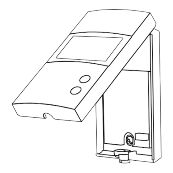
1
Unlock and lift the
thermostat cover.
4
Use the provided screws and
wall anchors to fix the
thermostat's base on the wall.
Electric floor heating with electric
baseboard on the 2nd heating stage
Hot water valve
C
R
W1
W2
S1
Electric baseboard
S 2
CONNECT YOUR THERMOSTAT TO THE GT130 GATEWAY OR A COMPATIBLE ZIGBEE SYSTEM
1
Initiate the connectivity session
by pressing the RF signal button
on the GT130 gateway. The
indicator light will start flashing.
Compatible Zigbee gateway:
refer to the installation guide for
the latter.
3
Connect all your
thermostats the same way,
by going to the next
closest thermostat.
INSTALL YOUR THERMOSTAT
2
If necessary, mark and drill the
appropriate fastening holes using the
installation template. If needed, use
the wall anchors included.
5
Replace and lock the
thermostat cover.
Electric floor heating
Floor sensor
Electric baseboard
120 V
24 V
240 V
24 Vac
347 V
Valve
normally closed
For use in floor or ambient
Floor sensor
mode with floor limit.
Not required for ambient
mode alone.
2
3rd
1st
2nd
Hub
Depending on the heating system,
insert each wire into its terminal
and screw firmly. (See connection
layouts outlined in the following
pages.)
6
Power up the thermostat.
CONNECTION OF THE FLOOR SENSOR
(OPTIONAL)
Only for control applications in floor (F) mode or with floor limit.
Connect your thermostat to the network
by pressing briefly and simultaneously
on the
and
buttons.
On the thermostat display:
Blinks: Connecting
Remains lit: Connected
If the connectivity fails, the
symbol will disappear from the
Alimentez le thermostat.
display. Refer to our Website to
troubleshoot the unit.
4
When all your devices are connected, close the
connectivity session of your GT130 gateway or
your compatible Zigbee gateway.
Sensor
Advertisement

Summary of Contents for NORDIK TH1420ZB
- Page 1 If needed, use and screw firmly. (See connection the wall anchors included. layouts outlined in the following pages.) TH1420ZB Installation Guide Use the provided screws and Replace and lock the Power up the thermostat. wall anchors to fix the thermostat cover.
- Page 2 (SSR) The obligation of NORDIK RADIANT, under the terms of this warranty, will be to • Electric floor heating (activated by a relay) supply a new unit and this releases the manufacturer from paying the installation costs or other secondary charges linked to replacing the unit or the components.