
Summary of Contents for MILLASUR Anova TC108LH
- Page 1 Lawnmower tractor TC108LH Instructions and user manual Millasur SLU Rúa Eduardo Pondal, nº 23 - Pol. Ind. Sigüeiro 15688 - Oroso - A Coruña - 981 696 465 - www.millasur.com...
- Page 2 Anova wishes to congratulate you for having chosen one of our products and guarantees you the assistance and cooperation that has always distinguished our brand over time. This machine is designed to last many years and to be very useful if it is used according to the instructions contained in the user manual.
- Page 3 INDEX 1. SECURITY INSTRUCTIONS 1.1. Position security labels 1.2. Please note the following security points 1.3. General safety rules 1.4. Security labels 1.5. Regulation for trailer 2. TECHNICAL SPECIFICATIONS 3. PRODUCT DESCRIPTION 4. UNPACKING AND ASSEMBLY 4.1. Unpacking 4.2. Steering wheel mounting 4.3.
-
Page 4: Security Instructions
1. SECURITY INSTRUCTIONS Important The lawn tractor must always be used with the utmost caution. So that safety precautions and operating instructions are always at hand, labels have been attached to the machine showing pictographs illustrating the main operating precautions. If you use the machine other than the way it was designed or ignore the instructions for safe use, maintenance and repair, it is... -
Page 5: General Safety Rules
1.2. Please note the following security points The machine should never be left in a condition that would allow an untrained or unauthorized person to use this machine. The operator must take all due care and diligence for the safety of and with respect to those nearby while using the machine. - Page 6 6. All drivers should seek and obtain professional, practical instruction. Such instruction should emphasize: The need for care and concentration when working with mounting machines. You cannot use the brake to regain control of a ride-on machine that is sliding down a hill.
- Page 7 Engage gear slowly and always keep the machine in gear, especially when going downhill. Machine speeds should be kept low on grades and during sharp turns. Be alert for drop-offs and other hidden hazards. Never mow across the face of the slope. 6.
-
Page 8: Security Labels
1.4. Security labels Your machine must be used with care. That is why labels with illustrations have been placed on the machine, to remind you of the main precautions to take during its use. These labels must be considered an integral part of the machine. If a label comes off or becomes illegible, it must be replaced. -
Page 9: Technical Specifications
2. TECHNICAL SPECIFICATIONS TC108LH Power 13kW - 17.50HP Engine Loncin - twin (V-Twin) Displacement 586cc Engine speed 2400min-1 Sound pressure level at the operator LpA: 82.2dB(A)KpA: 3dB(A) Guaranteed sound power level (2000/14/EC) LWA: 100dB(A) Blade Double ah: 3.24 m/s2 Extremities Kh: 0.16m/s2 Vibration ah: 2.77 m/s2... -
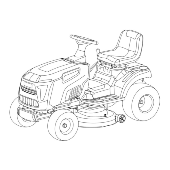
Page 10: Product Description
3. PRODUCT DESCRIPTION 3.1. Machine identification The label located on the support of the seat has the essential data of each machine. 1. Name and address of the manufacturer 2. Type of machine. 3. Blade speed in rpm (if indicated). 4. -
Page 11: Unpacking And Assembly
4. UNPACKING AND ASSEMBLY For storage and transportation purposes, some components of the machine are not installed at the factory and must be assembled after unpacking. Follow the instructions below. Important The machine is supplied without engine oil or fuel. Before starting the engine, fill with oil and fuel by following the instructions given in the engine manual. -
Page 12: Seat Assembly
4.2. Steering wheel mounting Place the machine on a level surface and straighten the front wheels. Mount the shaft (1) in the couplings and tighten the M8x25 screw (2). (Use the 5 hex key in the accessory tools.) Install the steering shaft cover (3). Insert the splined hub (4) onto the shaft (1), mounting handwheel (5), spacer (6) and M8 locknut (7). - Page 13 4.3.1. Assembly seat with armrests (*Optional) Fix the right armrest (1) on the seat with three M8 screws (2) using the Allen key in the accessory tools, and fix the left armrest (3) on the seat in the same way Fit retaining ring (1) onto pin (2), use pin to attach seat (3) to bracket and snap onto retaining ring (4).
-
Page 14: Battery Connection
4.4. Battery connection # The electrolytic fluid is a sulfuric acid solution. Hazard Sulfuric acid is corrosive and dangerous. Sulfuric acid can cause blindness or severe burns. Keep out of reach of children. In the case of EU countries, never dispose of any power tools in the household waste. In order to comply with the European Directive 2012/19/EC on old electrical and electronic equipment and its implementation in national laws, old power tools must be separated from other waste and disposed of in an environmentally friendly manner, e.g. - Page 15 4.6. Side Deflector Mount Insert the spring pin (1) and washer (2) into the right end of the pin (3); Insert the pin shaft into the side baffle (4), bracket (6), and torsion spring (5) in sequence, and insert the washer (2) and spring latch (1) into the other end.
- Page 16 4.8. Trailer kit mounting Remove the tension arm bushing (2), M8×20 hex flange bolts (3) and M8 hex flange lock nuts (1) that secure the gearbox cover (4); Insert the bushing (2) into the two holes where the bolts were just removed, align the tow plate (5), and then install the M8×40 hex flange bolts (3), M8 hex flange lock nut ( 1) and then tighten the bolt.
-
Page 17: Controls And Instruments
5. CONTROLS AND INSTRUMENTS 5.1. throttle lever 5.2. Steering wheel 5.3. Blade start/stop knob 5.4. ignition key switch 5.5. Brake pedal 5.6. Parking brake lever 5.7. driving drive 5.8. Gear shift lever (for manual gear model). 5.9. Cutting height adjustment lever 5.10. -
Page 18: Ignition Key Switch
5.3. Blade start/stop knob The blade start/stop knob is located on the right hand console, opposite the key switch. The blade start/stop knob operates the electric clutch. Pull the knob up to engage the blades or push it down to disengage the blades. 5.4. - Page 19 5.7. Driving pedals (*Valid for hydrostatic transmission model) This pedal engages the drive at the wheels and also modulates the forward and reverse speeds of the machine. To activate the feed, press it towards "F" with the toe. As the pressure on the pedal increases, the speed of the machine increases.
-
Page 20: Security Recommendations
6. INSTRUCTIONS FOR USE 6.1. Security recommendations Attention The machine must only be used for the purpose for which it was designed (cutting grass). Remember that the user is responsible for damages and injuries to other people or objects. Do not tamper with or remove safety devices installed on the machine for safety. The user is responsible for damages or losses to third parties. - Page 21 6.3. Instructions before starting work Before starting to cut, it is necessary to carry out various checks and operations to ensure that you can work efficiently and with maximum safety. 6.3.1. Seat adjustment To change the position of the seat, loosen the four set screws and slide it along the slots. Once you have found the correct position, tighten the four screws.
-
Page 22: Machine Use
Important: Do not spill gasoline on plastic parts to avoid damaging them. In case of accidental spills or leaks, rinse immediately with water. The guarantee does not cover damage to plastic parts of the bodywork or to the engine caused by gasoline. 6.3.4. - Page 23 Release the transmission engage pedal in neutral. Engage the parking brake. When starting cold, move the throttle to the "CHOKE" position indicated on the label. If the engine is already warm, move the lever between "SLOW" and "FAST". Turn ignition key ON and turn “ON” to make electrical contact, then turn to “START” to start engine.
- Page 24 Depress the brake pedal until the machine comes to a stop. Then reverse by moving the lever to the side and into the "R" position. (*Valid for manual transmission model - non-hydrostatic). Gradually release the brake pedal to engage the clutch, then begin to reverse. With the machine stopped, start reverse gear by pressing the transmission engagement pedal in the “R”...
- Page 25 6.4.8. Machine cleaning After use, clean the exterior of the machine, empty the grass discharge chute and shake to remove grass and other debris. Clean the plastic parts of the body with a damp sponge using water and detergent, being careful not to wet the motor, electrical parts or the electronic circuit board located under the dash.
- Page 26 6.4.11. Summary of the main steps to follow when using the machine For… You should… To start the Open the fuel cock, make sure all start conditions are met, and then turn the key engine move forward Press down on the pedal, engage gear, then gradually release the pedal. brake or stop Reduce engine speed and press the brake pedal.
-
Page 27: Lawn Maintenance
Adjust the indicator up or down until the left corner touches the slope (Figure 1 and Figure 2). If there is a gap below the indicator, the slope is too steep for safe operation (Figure Caveat Slopes are a major factor related to rollovers and accidents that can lead to injury or death. Do not operate the machine on slopes greater than 15 degrees, all slopes require extra caution. -
Page 28: Maintenance
is mowed less frequently, taller grass and weeds start to grow (as well as daisies and clovers etc.). It is always better to mow the grass when it is dry. The blades must be in good condition and well sharpened so that the grass is cut straight without a jagged edge that leads to yellowing at the ends. -
Page 29: Maintenance Schedule
7.2. Maintenance schedule 7.2.1. Maintenance schedule Operation Hours Filled 1. Machine Check Engine Oil Before each use Tire Pressure Check Before each use Security checks and controls Before each use Product damage check(2) Before each use General cleaning of the product after each use Checking the fixing and sharpening of the blades(2) every 25 hours... -
Page 30: Checks And Adjustments
7.2.3. Drums The battery must be carefully maintained to ensure a long life. The battery of the machine must always be charged: Before using the machine for the first time after purchase. Before leaving the machine in disuse for a long period. Before starting the machine after a long period of inactivity. -
Page 31: Disassembly And Replacement
7.4. Disassembly and replacement 7.4.1. Wheel replacement Stop the machine on level ground and place a block under a load- bearing part of the frame on the side where the wheel is to be changed. The wheels are held in place by a snap ring that can be removed with a screwdriver. - Page 32 Disassembly: Loosen the screw counterclockwise. Mounting: Check that the concave part of the disc flat washer washer presses against the blade. Washer Screw Reassemble the shaft hubs, making sure the key is set securely in place. Tighten the screws: Tighten clockwise with a torque wrench calibrated to 40~45N.m.
-
Page 33: Problem Solving
8. PROBLEM SOLVING Caveat Risk of injury if the engine is started inadvertently. Protect yourself against injury. Before doing any work on this mower: Turn off the motor. Remove the ignition key. Engage the parking brake. Wait until all moving parts have stopped and the engine has completely cooled down. Remove the spark plug connector from the engine so that the engine cannot be inadvertently started. -
Page 34: Warranty Period
9. WARRANTY Millasur guarantees that if your product suffers from a manufacturing defect during the established guarantee period, contact or go to your point of sale. Your purchase invoice must be kept as proof of the purchase date. Your tool must be returned to your dealer in an acceptable and clean condition, in its original molded case, if applicable to the unit, accompanied by your appropriate proof of purchase. - Page 35 Some countries do not allow limitations on how long an implied warranty lasts or do not allow the exclusion or limitation of consequential or incidental damages, in which case the above limitation and exclusion may not apply to you. This warranty gives you specific legal rights, and you may also have other rights which vary from state to state or country to country.
- Page 36 These are our standard warranty terms, but occasionally there may be additional warranty coverage not determined at the time of publication. For more information, contact your nearest official Anova distributor or by visiting www.millasur.com. Warranty service is only available through official Anova dealers. You can locate your nearest distributor on our distributor map at www.anova.es.
- Page 37 EXPLODED TC108LH...
-
Page 43: Ec Declaration Of Conformity
CE CERTIFICATE DISTRIBUTION COMPANY MILLASUR, SL RUA EDUARDO PONDAL, Nº 23 P.I. SIGÜEIRO 15688 OROSO - A CORUÑA SPAIN EC DECLARATION OF CONFORMITY In compliance with the different CE directives, this document confirms that, due to its design and construction, and according to the CE mark printed on it by the manufacturer, the machine identified in this document complies with the pertinent and fundamental health and safety requirements.
Need help?
Do you have a question about the Anova TC108LH and is the answer not in the manual?
Questions and answers