Table of Contents

Summary of Contents for Northern HS1275-08
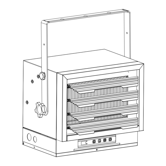
- Page 1 Electric Garage Heater S127 5-08 7 ,500W / 240V / 25589 BTU INSTALLATION & MAINTENANCE INSTRUCTIONS Intertek 5022073 CONFORMS TO UL STD 2021 CERTIFIED TO CSA STD C22.2 NO.46 ONSUMER: Retain this manual for future reference.
-
Page 2: Important Instructions
IMPORTANT INSTRUCTIONS This heater may include a visual alarm to warn that parts of the heater are getting excessively hot. If the alarm illuminates, immediately turn the heater off and inspect for any objects on or adjacent to the heater that may have blocked the airflow or otherwise DO NOT OPERATE THE HEATER WITH caused high temperatures to have occurred. -
Page 3: Specifications
TABLE OF CONTENTS ITEM PAGE # SPECIFICATIONS 17064 12778 3744W SAFETY INFORMATION WARNING NOTE: COMPATIBLE WITH A 240V LINE VOLTAGE DOUBLE POLE WALL THERMOSTAT. MUST BE INSTALLED BY A CERTIFIED ELECTRICIAN. -
Page 4: Safety Information
SAFETY INFORMATION WARNING LOCATING HEATER Figure 2... -
Page 5: Pre-Installation
LOCATING HEATER Figure 3 PRE-INSTALLATION Part Description Quantity... -
Page 6: Installation
INSTALLATION MOUNTING THE BRACKET NOTE: Figure 4a. Single-Screw Mounting Figure 4b. Double-Screw Mounting HANGING THE HEATER Figure 5 ADJUSTING AIR FLOW DIRECTION... - Page 7 INSTALLATION NOTE: Figure 6 NOTE: WARNING MULTIPLE VERTICAL ANGLES CEILING 90 deg rees s e e r g e 5 . 7 6 s e e r g e 45 deg rees 90 deg rees...
- Page 8 INSTALLATION CONNECTING THE POWER ACL1 Temperature Regulator ACL2 Heater’s External thermostat thermostat Sele ction Swi tch (He ater’s thermost at, External thermost at) If you will use an external temperature control (external thermostat) to control the heater to be operated or not, please follow below attention points: ACL1 Temperature Regulator...
- Page 9 INSTALLATION CONNECTING THE POWER TO PROTECT THE HEATING ELEMENT WARNING NOTE: WARNING WARNING...
- Page 10 INSTALLATION CONNECTING THE POWER Figure 7 Figura 7 OPERATING INSTRUCTIONS WARNING...
- Page 11 OPERATING INSTRUCTIONS Main Power Button: Heater Control Button: This button adjusts the 3 heating stages: OFF ,FA (Fan Only),AU : LOW (5600W displays "L") or High(7500W displavs“H”). Temperature/Timer Display: This LED display shows the set point for the temperature and timer functions. When either of these functions is activated, the display the set point for about 10 seconds and then fades to black.
-
Page 12: Maintenance
MAINTENANCE NOTE: REPLACEMENT PARTS Part Description Part# Part Description Part# Button surface sticker... -
Page 13: Troubleshooting
TROUBLESHOOTING DISPLAY PROBLEM ROOT CAUSE CORRECTIVE ACTION CODE The product does not have electricity entering The heater button is invalid... -
Page 14: Product Notes
PRODUCT NOTES...
Need help?
Do you have a question about the HS1275-08 and is the answer not in the manual?
Questions and answers