
Subscribe to Our Youtube Channel
Related Manuals for Tuxhorn tubra-USTA- L

Summary of Contents for Tuxhorn tubra-USTA- L
- Page 1 ® tubra - ÜSTA- L/XL Die solare Übergabestation für große Solaranlagen Montage- und Bedienungsanleitung...
-
Page 2: Table Of Contents
Inhalt Einführung ........................3 Verwendungszweck ....................3 Sicherheitshinweise ....................3 Mitgeltende Unterlagen .................... 3 Lieferung und Transport................... 3 Aufbau – Lieferumfang ....................4 Technische Daten......................5 Allgemein ......................... 5 Abmessungen ......................6 Druckverlust / Pumpenkennlinien ................7 Montage ......................... 8 Wandmontage ...................... -
Page 3: Einführung
Einführung ® Diese Anleitung beschreibt die Montage der Pumpengruppe für große Solaranlagen tubra ÜSTA L/XL sowie die Bedienung und die Wartung. Lesen Sie diese Anleitung vor Beginn der Montagearbeiten sorgfältig durch. Bei Nichtbeachtung entfallen sämtliche Garantie- und Gewährleistungsansprüche. Die Anleitung richtet sich an ausgebildete Fachhandwerker, die entsprechende Kenntnisse im Umgang mit Heizungsanlagen, Wasserleitungsinstallationen und mit Elektroinstallationen haben. -
Page 4: Aufbau - Lieferumfang
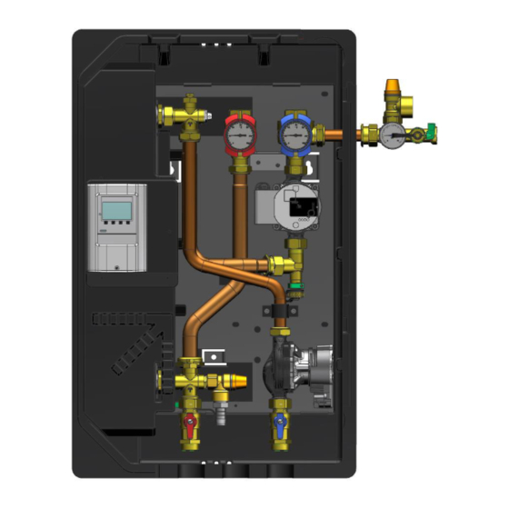
Aufbau – Lieferumfang Pos. Bezeichnung ET-Nummer Solar-Vorlauf-Kugelhahn mit 677.25.08.00.01 integriertem Thermometer Solar-Rücklauf-Kugelhahn mit 677.25.09.00.01 integriertem Thermometer Verbindungsrohr Solarsicherheitsventil 6 bar 855.51.32.00.01 Kesselfüll- und Entleerungshahn 676.00.10.00 Anschluss Membranausdehnungs- gefäß Manometer 676.01.83.00 Umwälzpumpe Solarkreislauf L: 130.15.88.00.01 / XL: 130.15.93.00.01 Umwälzpumpe Pufferkreislauf L: 130.15.74.00.01 / XL: 130.15.88.00.01 Kugelhahn (SPR) 668.22.65.00.01 Kugelhahn (SPV) -
Page 5: Technische Daten
Technische Daten Allgemein Bezeichnung / Typ ÜSTA-L ÜSTA-XL Max. Kollektorfläche [Flachkollektor] (kaskadiert) 90 m² 130 m² Nennleistung bei prim. 60-34°C/ sek. 27-53°C 45 kW 65 kW Umwälzpumpe Solarkreis (primär) Wilo Para ST Wilo Para ST 15/8 iPWM2 15/9 iPWM2 Leistungsaufnahme: 2-75 W 3-87 W Umwälzpumpe Speicherseite (sekundär) -
Page 6: Abmessungen
Abmessungen Art.-Nr. 910.38.02.00 Stand 2023/08/02 - 6 -... -
Page 7: Druckverlust / Pumpenkennlinien
Druckverlust / Pumpenkennlinien Art.-Nr. 910.38.02.00 Stand 2023/08/02 - 7 -... -
Page 8: Montage
Montage Wandmontage Bohrmaße entsprechend Zeichnung anzeich- nen und mit 10 mm bohren. Dübel setzen. Die beiden oberen Schrauben eindrehen. Schraubenkopf ca.3mm von der Wand abste- hen lassen. Station mit den oberen Halteösen in die Schrauben einhängen. Ausrichten. Schrauben festdrehen. Untere Fixierschraube eindrehen und festziehen. -
Page 9: Zubehör
Zubehör 4.3.1 WMZ-Set (optionales Zubehör) Volumenstromgeber VFS 2-40 l/min mit integr. Temperatursensor und zusätzlichem Pt1000 4.3.2 3-Wege Umschaltventil (optionales Zubehör) Dreiwege-Umschaltventil mit Stellmotor +, 2-Punkt-Ansteuerung mit Dauerspannung 230 V, 50 Hz max. 110°C, PN6 Differenzdruck: max. 0,4 bar Schaltzeit: 18s / 90° 4.3.3 Doppelumschaltung (optionales Zubehör) -
Page 10: Hydraulischer Anschluss
Hydraulischer Anschluss Beispieldarstellung, erhebt keinen Anspruch auf Vollständigkeit und ersetzt keine fachmännische Planung. Solarvorlauf Solarrücklauf Speichervorlauf Speicherrücklauf Achtung! Zum Eindrehen der Anschlüsse die Griffe der Kugelhähne in Stellung „geschlossen“ drehen (Griffe stehen waagerecht). Beim Festdrehen der Anschlüsse am Kugel- hahn gegenhalten [A]! Kugelhähne wieder in Stellung „geöffnet“... -
Page 11: Elektrischer Anschluss
Elektrischer Anschluss 4.5.1 Allgemein Arbeiten an der elektrischen Anlage sowie das Öffnen von Elektrogehäusen darf nur in spannungsfreiem Zustand und nur von autorisiertem Fachpersonal durchgeführt werden. Bei den Anschlüssen auf richtige Klemmenbelegung und Polarität achten. Die Regelung und die elektrischen Bauteile vor Überspannung schützen. Bei unsachgemäßem elektrischen Anschluss besteht Lebensgefahr durch Stromschlag. -
Page 12: Bedienung
B e d i e n u n g Funktion der Schwerkraftbremsen Die Schwerkraftbremsen sind auf der Solarseite jeweils im Vorlauf-[1] und Rücklauf- Kugelhahn [2] integriert. Auf der Speicherseite befindet sich die Schwerkraftbremse im Rück- lauf-Kugelhahn [15]. Die Betätigung erfolgt durch Drehung der Griffe der Kugelhähne. Betriebsstellung Zur Verhinderung der Schwerkraftzirkulation dürfen die Ventilteller nicht angelüftet sein. -
Page 13: Befüllen, Spülen Und Entleeren Der Solarseite
B e f ü l l e n , S p ü l e n u n d E n t l e e r e n d e r S o l a r s e i t e Befüllen Zum Befüllen der Solaranlage muss der Vorlaufkugelhahn in Betriebsstellung und der... -
Page 14: Kontrollspülung
Kontrollspülung Schritt 1 - Kollektorkreis Vorlaufkugelhahn [1] in Betriebsstellung, Rücklaufkugelhahn [2] in waagerechter Stellung. Befüllschlauch am KFE-Hahn [4a] anschließen. Entleerschlauch am KFE-Hahn [4b] anschließen. Die KFE-Hähne öffnen und die Kontrollspülung wie dargestellt durchführen. Die KFE-Hähne nach dem Spülvorgang wieder absperren. Schritt 2 - Pumpe Vorlaufkugelhahn [1] absperren, Rücklaufkugel- hahn [2] in Betriebsstellung. -
Page 15: Service / Pwt Austauschen
Service / PWT austauschen Heizungskreis Das Heizungssystem nur mit filtriertem, aufbereitetem Wasser nach VDI 2035 befüllen und Anlage vollständig entlüften. Dichtheitsprüfung Alle Bauteile der Anlage inkl. aller werksseitig vorgefertigten Elemente auf Dichtheit überprü- fen und bei eventuellen Undichtigkeiten entsprechend abdichten. Dabei den Prüfdruck und die Prüfdauer dem jeweiligen Verrohrungssystem und dem jeweiligen Betriebsdruck anpas- sen. -
Page 16: Regelung
R e g e l u n g Beachten Sie hierzu auch die Betriebsanleitung der verwendeten Regelung. Übersicht Systeme Funktionspiktogramme Beschreibung Anlagenschema 14 ÜSTA-mat ohne Umschaltventil Anlagenschema 26 ÜSTA-mat mit 1 Umschaltventil und mit 2 Umschaltventilen Art.-Nr. 910.38.02.00 Stand 2023/08/02 - 16 -... -
Page 17: Üsta-L/Xl Ohne Umschaltventil
ÜSTA-L/XL ohne Umschaltventil Der Regler vergleicht die Temperatur an dem Kollektorsensor S1 mit der Temperatur an S2. Ist die gemessene Temperaturdifferenz größer als der eingestellte Wert für die Einschalt- temperaturdifferenz, so wird die Pumpe (P1) in Betrieb genommen; der Primärkreislauf erwärmt sich. - Page 18 7.2.1 Belegungen 7.2.2 Einstellungen Folgende Einstellungen sind im ausgewählten Programm hinterlegt und bilden die Grundfunktion ab. Je nach Anlagenkonfiguration müssen bei der Inbetriebnahme noch anlagenspezifische Einstellungen vorgenommen werden. Programm: Anlagenschema 14 - Solar mit Wärmetauscher Ein- und Ausgänge Bezeichnung Einstellung Bemerkung Regler Regler...
- Page 19 Werkseinstellung / Einstellungsparameter Bezeichnung Werkseinstellung Einzustellender Wert Anlagenschema wählen °C Temperatureinheit 20°C Tmin S1 15 °C 10 °C Delta T Solar S2 Ein 7 °C 4 °C Delta T Solar S2 Aus 60°C 85°C Tmax S2 Anlagenschutz AS T Ein AS T Aus Kollektorschutz Rückkühlung...
-
Page 20: Üsta-L/Xl Mit 1Uv Und 2Uv
ÜSTA-L/XL mit 1UV und 2UV Der Regler vergleicht die Temperatur an dem Kollektorsensor S1 mit der Temperatur an S3 (Speicher 1 unten). Ist die gemessene Temperaturdifferenz größer als der eingestellte Wert für die Einschalttemperaturdifferenz, so wird die Pumpe (P1) in Betrieb genommen; der Pri- märkreislauf erwärmt sich. - Page 21 1 Umschaltventil Beispieldarstellung, erhebt keinen Anspruch auf Vollständigkeit und ersetzt keine fachmännische Planung. Solarvorlauf SPV 1 Speichervorlauf Solarrücklauf SPV 2 Speichervorlauf 2 Speicherrücklauf Sen. 1 Kollektor Solar Sen. 2 Speicher (oben) Sen. 3 Speicher (unten) Sen. 4 Vorlauf externer WT Relais 1 Pumpe Kollektorfeld Relais 2...
- Page 22 2 Umschaltventile Beispieldarstellung, erhebt keinen Anspruch auf Vollständigkeit und ersetzt keine fachmännische Planung. Solarvorlauf SPV 1 Speichervorlauf 1 Solarrücklauf SPV 2 Speichervorlauf 2 SPR 1 Speicherrücklauf 1 SPR 2 Speicherrücklauf 2 Sen. 1 Kollektor Solar Sen. 2 Speicher (oben) Sen. 3 Speicher (unten) Sen.
- Page 23 7.3.1 Belegungen * bei Anschluss von 2 Umschaltventilen beide Ventile parallel auf R3 anschließen! 7.3.2 Einstellungen Folgende Einstellungen sind im ausgewählten Programm hinterlegt und bilden die Grundfunktion ab. Je nach Anlagenkonfiguration müssen bei der Inbetriebnahme noch anlagenspezifische Einstellungen vorgenommen werden. Programm: Anlagenschema 26 - Solar mit Wärmetauscher und UV Ein- und Ausgänge Bezeichnung...
- Page 24 Werkseinstellung / Einstellungsparameter Bezeichnung Werkseinstellung Einzustellender Wert Anlagenschema wählen °C Temperatureinheit Priorität S2 15 °C 10 °C Delta T Solar S2 Ein 7 °C 4 °C Delta T Solar S2 Aus 60°C 85°C Tmax S2 Priorität S3 15 °C 10 °C Delta T Solar S2 Ein 7 °C 4 °C...
-
Page 25: Inbetriebnahme
I n b e t r i e b n a h m e Voraussetzung für die Inbetriebnahme ist eine vollständige Installation aller hydraulischen und elektrischen Komponenten, sowie die ordnungsgemäße Befüllung, Entlüftung und Druckeinstellung. Alle Kugelhähne müssen in Betriebsstellung gedreht sein. Bitte beachten Sie hierzu die entsprechende Anleitung der Regelung. -
Page 26: Störungen / Fehlerbehebung
S t ö r u n g e n / F e h l e r b e h e b u n g Liegt eine Fehlermeldung vor, wird diese im Display der Regelung angezeigt. Bitte beachten Sie hierzu die entsprechende Anleitung der Regelung. Störung Mögliche Ursache Behebung... -
Page 27: Pumpeninformation
P u m p e n i n f o r m a t i o n Logik PWM2 < 7% Pumpe aus 7-12% Min. Leistung (Betrieb) 12-15% Min. Leistung (start-up) 15-95% proportionaler Leistungsbereich > 95% Max. Leistung Art.-Nr. 910.38.02.00 Stand 2023/08/02 - 27 -... - Page 28 Händler Gebr. Tuxhorn GmbH & Co. KG • Senner Straße 171 • 33659 Bielefeld Tel.: +49 (0) 521 44 808-0 • Fax: +49 (0) 521 44 808-44 • www.tuxhorn.de...
- Page 29 ® tubra - ÜSTA- L/XL Solar transmission station for large-scale solar energy systems Assembly and operating guide...
- Page 30 Contents Introduction........................3 Functional application ....................3 Safety instructions ....................3 Applicable documents ....................3 Delivery and transport ....................3 Layout – scope of delivery ....................4 Technical Data ....................... 5 General instructions ....................5 Dimensions ......................6 Pressure loss – pump characteristics............... 7 Assembly ........................
-
Page 31: Introduction
Introduction ® This manual describes the installation process for the tubra -ÜSTA L/XL transmission sta- tion, as well as its operating and maintenance procedures. Read this manual carefully before starting any installation work. Non-compliance will invalidate all claims under the guarantee and warranty. This manual is intended for trained specialists with an adequate level of expertise in handling heating systems, water pipe installations and electrical installations. -
Page 32: Layout - Scope Of Delivery
Layout – scope of delivery Item Designation ET-Number Solar supply ball valve with integrated 677.25.08.00.01 thermometer Solar return ball valve with integrated 677.25.09.00.01 thermometer Connecting pipe Solar safety valve, 6 bar 855.51.32.00.01 Boiler filling and drain valve 676.00.10.00 Connection to membrane expansion vessel Pressure gauge 676.01.83.00... -
Page 33: Technical Data
Technical Data General instructions Designation/type ÜSTA-L ÜSTA-XL Max. collector area [flat plate collector] (cascaded) 90 m² 130 m² Rated output at prim. 60-34°C/sec. 27-53°C 45 kW 65 kW Solar circuit circulation pump (primary) Wilo Para ST Wilo Para ST 15/8 iPWM2 15/9 iPWM2 power input: 2-75 W... -
Page 34: Dimensions
Dimensions 910.38.02.00 Last updated 2023/08/02 - 6 -... -
Page 35: Pressure Loss - Pump Characteristics
Pressure loss – pump characteristics 910.38.02.00 Last updated 2023/08/02 - 7 -... -
Page 36: Assembly
Assembly Wall-mounted assembly Score the fastening points for the mounting brackets as shown in the adjacent figure, and drill with ø10 mm. Insert wall plugs. Screw in the two upper screws. Let the screw head protrude approx. 3 mm from the wall. Hook the station into the screws using the upper retaining lugs. -
Page 37: Accessories
Accessories 4.3.1 WMZ-Set (optional accessory) Volume flow transmitter VFS 2-40 l/min with integrated temperature sensor and additional Pt1000 4.3.2 Three-way switch over valve (optional accessory) Three-way switch over valve with servomotor +, 2-point control with continuous voltage 230 V, 50 Hz max. -
Page 38: Hydraulic Connection
Hydraulic connection This is a sample illustration which does not claim to be exhaustive; it does not replace specialist planning. Solar supply line Solar return line Tank supply Tank return Caution! To close the connections on the ball valves, turn the handles on the ball valves to the "closed"... -
Page 39: Electrical Connections
Electrical connections 4.5.1 General instructions Only authorised, specialist personnel are permitted to open electrical housings and work on the electrical system after de-energising the equipment. When establishing connections, make sure the terminal assignments and polarity are correct. Protect the control unit and electrical components against excess voltage. -
Page 40: Operation
O p e r a t i o n Gravity brake function The gravity brakes are built into the feed [1] and return ball valves [2]. The gravity brake is located in the return ball valves [15] on the storage tank side. The valves are operated by turning the ball valve handles. -
Page 41: Filling, Flushing And Draining The Solar Side
Filling, flushing and draining the solar side Filling In order to fill the solar energy system, the supply ball valve must be set in the operating position and the return ball valve must be closed. Connect the filling hose to the boiler filling and drain valve [4a]. -
Page 42: Check Flushing
Check flushing Step 1 – Collector circuit Set the supply ball valve [1] to the operating position, set the return ball valve [2] in horizontal position. Connect the filling hose to the boiler filling and drain valve [4a]. Connect the drain hose to the boiler filling and drain valve [4b]. -
Page 43: Service / Heat Exchanger Replacement
Service / heat exchanger replacement Heating circuit Fill the heating system only with filtered, treated water according to VDI 2035 and vent the system completely. Leak test Check all components of the system, including all elements prefabricated at the factory, for leaks and seal them accordingly in the event of any leaks. -
Page 44: Regulation
R e g u l a t i o n Please also refer to the operating instructions of the controller used. Overview systems Function pictograms Description System diagram 14 ÜSTA-mat without switch over valve System diagram 26 ÜSTA-mat with 1 switch over valve and with 2 switch over valves 910.38.02.00 Last updated 2023/08/02... -
Page 45: Üsta-L/Xl Without Switch Over Valve
ÜSTA-L/XL without switch over valve The controller compares the temperature at the temperature sensor S1 with the temperature at S2. If the measured temperature difference is greater than the preset value for the switch- on temperature difference, then the pump (P1) is operated; the primary circuit heats up. At the same time, the temperature difference between S3 and S2 is determined in comparison to the switch-on temperature difference that is separately configurable for the secondary pump (external heat exchanger). - Page 46 7.2.1 Pin assignments 7.2.2 Settings The following settings are stored in the selected program and represent the basic function. Depending on the plant configuration, plant-specific settings must still be made during startup. Program: System diagram 14 - Solar with heat exchanger Inputs and outputs Designation Setting...
- Page 47 Factory setting / Setting parameters Designation Factory setting Value to be set Select system diagram Temperature unit °C Tmin S1 20°C Delta T Solar S2 On 15 °C 10 °C Delta T Solar S2 Off 7 °C 4 °C Tmax S2 60°C 85°C System protection...
-
Page 48: Üsta-L/Xl 1Uv And 2Uv
ÜSTA-L/XL 1UV and 2UV The controller compares the temperature at the collector sensor S1 with the temperature at S3 (storage tank 1 below). If the measured temperature difference is greater than the set value for the switch-on temperature difference, the pump (P1) is started up; the primary cir- cuit heats up. - Page 49 1 Switch over valve This is a sample illustration which does not claim to be exhaustive; it does not replace specialist planning. Solar supply SPV 1 Tank supply 1 Solar return SPV 2 Tank supply 2 Tank return Sen. 1 Solar collector Sen.
- Page 50 2 Switch over valves This is a sample illustration which does not claim to be exhaustive; it does not replace specialist planning. Solar supply SPV 1 Tank supply 1 Solar return SPV 2 Tank supply 2 SPR 1 Tank return 1 SPR 2 Tank return 2 Sen.
- Page 51 7.3.1 Pin assignments * when connecting 2 switch over valves, connect both valves in parallel to R3! 7.3.2 Settings The following settings are stored in the selected program and represent the basic function. Depending on the plant configuration, plant-specific settings must still be made during startup. Program: System diagram 26 - Solar with heat exchanger and UV Inputs and outputs Designation...
- Page 52 Factory setting / Setting parameters Designation Factory setting Value to be set Select system diagram Temperature unit °C Priority S2 Delta T Solar S2 On 15 °C 10 °C Delta T Solar S2 Off 7 °C 4 °C Tmax S2 60°C 85°C Priority S3...
-
Page 53: Commissioning
C o m m i s s i o n i n g A prerequisite for commissioning is complete installation of all hydraulic and electrical components, as well as proper filling, venting and pressure setting. All ball valves must be turned to operating position. Please refer to the corresponding instructions for the control system. -
Page 54: Malfunctions / Troubleshooting
M a l f u n c t i o n s / t r o u b l e s h o o t i n g If an error message is output, it appears on the control unit display. Please observe the corresponding instructions for the control unit. -
Page 55: Pump Information
P u m p i n f o r m a t i o n Logic PWM2 < 7% Pump off 7-12% Min. power (operational) 12-15% Min. power (start-up) 15-95% proportional power range > 95% Max. power 910.38.02.00 Last updated 2023/08/02 - 27 -... - Page 56 Reseller Gebr. Tuxhorn GmbH & Co. KG • Senner Straße 171 • 33659 Bielefeld Tel.: +49 (0) 521 44 808-0 • Fax: +49 (0) 521 44 808-44 • www.tuxhorn.de...
- Page 57 ® tubra - ÜSTA- L/XL La stazione di trasferimento solare per il carico stratificato per grandi impianti solari Istruzioni di assemblaggio e d'uso...
- Page 58 Contenuto Introduzione........................3 Scopo d'utilizzo ......................3 Avvertenze di sicurezza ................... 3 Documentazione associata ..................3 Fornitura e trasporto ....................3 Struttura – Fornitura ....................... 4 Dati tecnici ........................5 Generale ........................5 Dimensioni ....................... 6 Perdita di pressione ....................7 Montaggio ........................
-
Page 59: Introduzione
Introduzione Le presenti istruzioni descrivono il montaggio della stazione solare per grandi impianti solari ® tubra -ÜSTA L/XL , il suo impiego e la sua manutenzione. Leggere attentamente le presenti istruzioni prima di iniziare i lavori di montaggio. La mancata osservanza di dette istruzioni farà decadere tutti i diritti alle prestazioni di garan- zia commerciale o legale. -
Page 60: Struttura - Fornitura
Struttura – Fornitura Pos. Denominazione Codice pezzo di ricambio Rubinetto a sfera di mandata solare 677.25.08.00.01 con termometro integrato Rubinetto a sfera di ritorno solare con 677.25.09.00.01 termometro integrato Tubo di raccordo Valvola di sicurezza solare 6 bar 855.51.32.00.01 Rubinetto di riempimento e svuota- 676.00.10.00 mento della caldaia Collegamento serbatoio di espansione... -
Page 61: Dati Tecnici
Dati tecnici Generale Descrizione / Tipo ÜSTA-L ÜSTA-XL 90 m² 130 m² Max. superficie di collettori [collettore piatto Potenza nominale con 60-34°C lato prim./ 27-53°C 45 kW 65 kW lato sec. Pompa di circolazione circuito solare (lato primario) Wilo Para ST Wilo Para ST 15/8 iPWM2 15/9 iPWM2... -
Page 62: Dimensioni
Dimensioni N. art. 910.38.02.00 Ultimo aggiornamento 2023/08/02 - 6 -... -
Page 63: Perdita Di Pressione
Perdita di pressione N. art. 910.38.02.00 Ultimo aggiornamento 2023/08/02 - 7 -... -
Page 64: Montaggio
Montaggio Montaggio a parete Segnare i punti di fissaggio sulla parete e creare fori con 10 mm. Inserire i tasselli nei fori. Avvitare le due viti superiori. Far sporgere la testa della vite di circa 3 mm dalla parete. Agganciare la stazione alle viti con gli occhielli di fissaggio superiori. -
Page 65: Accessori
Accessori 4.3.1 Set Contatore di calore (Accessorio opzionale) Trasmettitore di portata VFS 2-40 l/min con sensore di temperatura integrato e Pt1000 aggiuntivo 4.3.2 Valvola di commutazione a 3 vie (Accessorio opzionale) Valvola di commutazione a tre vie con servomotore, Controllo a 2 punti con tensione elettrica continua 230 V, 50 Hz max. -
Page 66: Attacco Idraulico
Attacco idraulico Illustrazione esemplificativa, non ha alcuna pretesa di completezza e non sostituisce la proget- tazione a regola d'arte. Mandata solare Ritorno solare Mandata serbatoio 1 (in alto) Ritorno serbatoio 1 Attenzione! Per avvitare gli attacchi dei rubinetti a sfera di mandata solare e di riflusso solare girare le impugnature dei rubinetti a sfera in posizione "chiuso“... -
Page 67: Allacciamento Elettrico
Allacciamento elettrico 4.5.1 Generale I lavori sull'impianto elettrico e l'apertura delle custodie dei componenti elettrici possono essere effettuati solamente a corrente elettrica scollegata e solo da personale specializzato opportunamente autorizzato. Negli attacchi verificare la corretta polarità e il corretto collegamento dei morsetti. Proteggere il dispositivo di regolazione e i componenti elettrici dalla sovratensione. -
Page 68: Funzione
F u n z i o n e Freno di gravità I freni a gravità sono integrati nella valvola a sfera di mandata [1] e nella valvola a sfera di ritorno [2] sul lato solare. Sul lato del serbatoio, il freno di gravità si trova nella valvola a sfera di ritorno [10]. -
Page 69: Travasare, Lavare E Svuotare
T r a v a s a r e , l a v a r e e s v u o t a r e Travasare Per riempire e risciacquare l'impianto solare, il rubinetto a sfera di mandata è in posizione d'esercizio e il rubinetto a sfera di ritorno è... -
Page 70: Risciacquo Di Controllo
Risciacquo di controllo Fase 1 – Circuito del collettore Rubinetto a sfera di mandata [1] in posizione di funzionamento, rubinetto a sfera di ritorno [2] in posizione orizzontale. Collegare il tubo flessibile di travaso al rubinetto KFE [4a]. Collegare il tubo flessibile di svuotamento al rubinetto KFE [4b]. -
Page 71: Servizio / Sostituzione Del Scambiatore Di Calore
Servizio / sostituzione del scambiatore di calore Circuito riscaldamento Riempire il sistema di riscaldamento esclusivamente con acqua filtrata ed eventualmente trattata secondo la norma VDI 2035 e sfiatare completamente l'impianto. Controllo della tenuta Verificare la tenuta di tutti i componenti dell'impianto inclusi tutti gli elementi prefabbricati in stabilimento;... -
Page 72: Regolamento
R e g o l a m e n t o In tal caso osservare anche le istruzioni per l'uso del dispositivo di regolazione in uso. Sistemi generali Pittogrammi delle funzioni Descrizione Schema del sistema 14 ÜSTA-mat senza valvola di commutazione Schema del sistema 26 ÜSTA-mat con 1 valvola di commutazione e... -
Page 73: Üsta-L/Xl Senza Valvola Di Commutazione
ÜSTA-L/XL senza valvola di commutazione Il regolatore confronta la temperatura presso il sensore di temperatura S1 con la temperatura presso S2. Nel caso la differenza della temperatura misurata sia superiore al valore imposta- to per la differenza della temperatura di accensione, sarà attivata la pompa (P1) ed il circuito primario si riscalda. - Page 74 7.2.1 Assegnazioni 7.2.2 Impostazioni Le seguenti impostazioni sono salvate nel programma selezionato e costituiscono il funzio- namento di base. A seconda della configurazione dell'impianto occorre effettuare altre impo- stazioni specifiche dell'impianto durante la messa in funzione. Programma: Schema di sistema 14 - Solare con scambiatore di calore Ingressi ed uscite Denominazione Impostazione Commento...
- Page 75 Impostazione di fabbrica / Parametri di impostazione Impostazione di Denominazione Valore da impostare fabbrica Selezionare il diagramma di sistema Unità di temperatura °C Tmin S1 20°C Delta T Solar S2 On 15 °C 10 °C Delta T Solar S2 Off 7 °C 4 °C Tmax S2...
-
Page 76: Üsta-L/Xl 1Uv E 2Uv
ÜSTA-L/XL 1UV e 2UV Il regolatore confronta la temperatura sulla sonda del collettore S1 con la temperatura su S3 (serbatoio di stoccaggio 1 in basso). Se la differenza di temperatura misurata è superiore al valore impostato per la differenza di temperatura di accensione, la pompa (P1) viene avviata; il circuito primario si riscalda. - Page 77 1 valvola di commutazione Illustrazione esemplificativa, non ha alcuna pretesa di completezza e non sostituisce la pianificazione a regola d’arte Mandata solare SPV 1 Mandata serbatoio 1 Ritorno solare SPV 2 Mandata serbatoio 2 Ritorno serbatoio Sen. 1 Collettore solare Sen.
- Page 78 2 valvole di commutazione Illustrazione esemplificativa, non ha alcuna pretesa di completezza e non sostituisce la pianificazione a regola d’arte Mandata solare SPV 1 Mandata serbatoio 1 Ritorno solare SPV 2 Mandata serbatoio 2 SPR 1 Ritorno serbatoio 1 SPR 2 Ritorno serbatoio 2 Sen.
- Page 79 7.3.1 Assegnazioni * Quando si collegano 2 valvole di commutazione, collegare entrambe le valvole in parallelo a R3! 7.3.2 Impostazioni Le seguenti impostazioni sono salvate nel programma selezionato e costituiscono il funzio- namento di base. A seconda della configurazione dell'impianto occorre effettuare altre impo- stazioni specifiche dell'impianto durante la messa in funzione.
- Page 80 Impostazione di fabbrica / parametri di impostazione Impostazione di Denominazione Valore da impostare fabbrica Selezionare il diagramma di sistema Unità di temperatura °C Priorità S2 Delta T Solar S2 On 15 °C 10 °C Delta T Solar S2 Off 7 °C 4 °C Tmax S2 60°C...
-
Page 81: Messa In Funzione
M e s s a i n f u n z i o n e Sarà possibile mettere in funzione l'impianto solamente se tutti i componenti idraulici ed elettrici sono stati completamente installati. Tutti i rubinetti a sfera devono essere girati in posizione di funzionamento. -
Page 82: Guasti / Risoluzione Dei Problemi
G u a s t i / r i s o l u z i o n e d e i p r o b l e m i Gli eventuali messaggi di errore vengono visualizzati sul display del dispositivo di regolazione. -
Page 83: Informazioni Inerenti Alla Pompa
I n f o r m a z i o n i i n e r e n t i a l l a p o m p a Logica PWM2 < 7% Pompa spenta 7-12% Potenza min. (funzinamento) 12-15% Potenza min. (start-up) 15-95% intervallo di prestazione proporzionale >... - Page 84 Rivenditore Gebr. Tuxhorn GmbH & Co. KG • Senner Straße 171 • 33659 Bielefeld Tel.: +49 (0) 521 44 808-0 • Fax: +49 (0) 521 44 808-44 • www.tuxhorn.de...
Need help?
Do you have a question about the tubra-USTA- L and is the answer not in the manual?
Questions and answers