Table of Contents
Advertisement
Quick Links
Advertisement
Table of Contents

Subscribe to Our Youtube Channel
Summary of Contents for CBS 2101
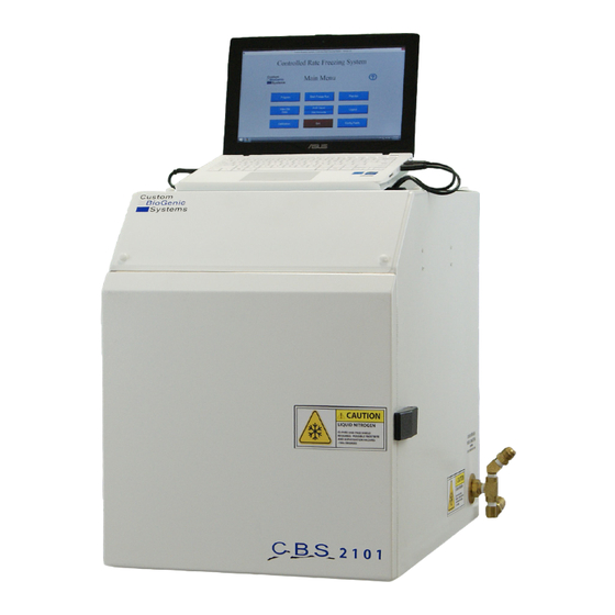
- Page 1 CUSTOM BIOGENIC SYSTEMS 2101 CONTROLLED RATE FREEZER SET-UP & TECHNICAL MANUAL www.custombiogenics.com 74100 Van Dyke Bruce Twp., MI 48065 1.800.523.0072 Tel: 1.586.331.2600 Fax: 1.586.331.2588 Leading the World with Innovative Cryopreservation Technology Solutions...
- Page 2 Also, read this manual completely before proceeding to set-up. If at any time you are unsure of the procedures for set-up and use of this product, please contact CBS or your CBS sales representative. NOTE: If equipment is used in a manner not specified by Custom Biogenic Systems, the protection provided by the equipment will be impaired.
- Page 3 LIQUID NITROGEN SAFETY IMPORTANT: The following section on LIQUID NITROGEN SAFETY should be read carefully and be followed completely, but is by no means a complete volume on the safe use of cryogenic liquids. All personnel should have a complete knowledge of the correct procedures, as well as the hazards of working with liquid nitrogen.
-
Page 4: Table Of Contents
Sample Probe Placement Canister Probe Placement Proper Run Trouble Shooting 37-38 2101 Rate Freezer Part I.D. 2101 Rate Freezer Plumbing Part I.D. Appendix A 41-48 Cleaning & Maintenance Solenoid Valve Maintenance Fuse Maintenance *THE PRODUCT IMAGES ARE FOR ILLUSTRATION PURPOSES ONLY AND MAY NOT BE AN EXACT REPRESENTATION OF THE PRODUCT. -
Page 5: Introduction
Unpacking Your 2101 Rate Freezer will arrive on a pallet in a box that is 30” x 30 “ x 30” (L x W x H) on a pallet that is 48” x 40”. Before unpacking check for any visual damage if there is visual damage be sure to sign the Proof of Delivery as damaged and notify Custom BioGenic Systems. -
Page 6: Detected Damage
Initial Installation Detected Damage Once all items are removed from their packaging, check them for damage. Also check that the unit is as ordered. If damage is detected after unpacking the rate freezer, immediately report it to the shipping agent and re-pack the rate freezer for return to the factory as described in the following section. Equipment Return Before returning damaged or malfunctioning equipment to the factory for repair, contact the sales organization from which you purchased the equipment. -
Page 7: Power Connections
Initial Installation Power Connections The rate freezer is designed to operate on either 120VAC or 220VAC (must be specified when unit is ordered), depending on the users needs. Check to make sure that the rate freezer voltage is the correct voltage for the local power system. -
Page 8: Controller Start Up
Controller Start Up www.custombiogenics.com... -
Page 9: Operating Instructions
For a more detailed explanation on how to calibrate your 2101 Rate freezer please refer to pages 23-30. D. START FREEZE RUN -This menu button brings up the profile and freeze name selection screen. -
Page 10: Turn On Computer
Operating Instructions Turn On Computer 1. Push and release the POWER button on the computer [not shown]. 2. The computer will ask you to log in. The user name is RateFreezer and the password is custombio. 3. Once you have logged in Click the Icon labeled Rate Freezer to launch the application. www.custombiogenics.com... - Page 11 21 CFR Part 11 Certified. The 2101 Controller Software is designed to address each ruling in 21 CFR Part 11. A list of the directives and an explanation on how the controller meets the directive is listed in Appendix A.
- Page 12 21 CFR PART 11 3. Log in as the Administrator: i. The first time you log in the user name and password are as follows: User name: default Password: administrator Note that both the user name and password are lower case. ii.
- Page 13 21 CFR PART 11 4. Enter the User Name and Full Name 5. Enter a Password then Retype the password 6. Select the User Level The first time that you are use the system, ensure that you create a new Administrator Account There are 4 possible User Levels: Operator 1- Has access to Program, Start Freeze Run, Preview and View Old Data ii.
- Page 14 21 CFR PART 11 Edit a User To Edit a User 1. Ensure that you are logged in as the Administrator 2. From the Main menu select User Accounts 3. Click Edit User 4. Change the information as necessary www.custombiogenics.com...
-
Page 15: Cfr Part
21 CFR PART 11 Delete a User To Delete a User 1. Ensure that you are logged in as the Administrator 2. From the Main menu select User Accounts 3. Click Delete User www.custombiogenics.com... - Page 16 21 CFR PART 11 Setting the Inactivity Timer According to the 21 CFR Part 11 ruling the system must allow you to set an inactivity timer. Once this time limit is reached the user is logged out and must log in again. To set the Inactivity Timer do the following: 1.
- Page 17 21 CFR PART 11 Setting the Password Expiration According to the 21 CFR Part 11 ruling, Passwords must expire (and therefore be changed) a mini- mum of every 90 Days. To set the expiration period do the following: 4. Ensure that you are logged in as the Administrator. 5.
- Page 18 21 CFR PART 11 Viewing the Audit Trail According to the 21 CFR Part 11 ruling the system must keep a complete history of all security related inter- actions with the system. The Audit Trail provides a record of all changes made to the Controlled Rate Freezer by users.
- Page 19 21 CFR PART 11 The system will now display a list of the events in the system. You can filter this list by date as follows: 1. Click on the Event Query Type drop down, change from All Events to “In Date Range”. 2.
- Page 20 21 CFR PART 11 Printing the Audit Trail: The Audit Trail can be printed from the same screen by clicking the Print Button. The system will print the records that are currently displayed in the grid. NOTE: The Audit Trail may contain information about users and passwords. Care must therefore be taken when printing this log to ensure that it is not accessible by unauthorized per- sons.
-
Page 21: Create A Program
Operating Instructions Create a Program 1. At the main menu click on the program button [A]. 2. Clicking the program button [A] will open a new window called PROGRAM PROFILE. The program profile screen is where you will enter the steps of the program. The step number [G] will automatically be cre- ated when entered. -
Page 22: Save A Program
Operating Instructions Save a Program After you have created a program, you may save, edit, or delete it. To save a program: 1. Create a program (see page 17; steps 1-8) 2. Click on the SAVE PROGRAM button [A]. 3. Type the name you wish to give to this program in the save profile window [B]. 4. -
Page 23: Edit A Program
Operating Instructions Edit a Program Custom BioGenic Systems has provided you with six preset programs that you can use as templates for many common freezing processes. (Both User-created and preset programs can be edited.) 1. At the main menu screen press the PROGRAM button [A]. 2. -
Page 24: Run A Program
Operating Instructions Run a Program Every time you run a program you create a unique set of data. In many cases you will wish to save this data using a unique file name; if you don’t your old program data will be overwritten by the latest data. 1. -
Page 25: Preview A Profile
Operating Instructions Preview a Profile NOTE: Custom BioGenics recommends that you preview a program before running it. By doing this you can often identify incorrect information by previewing the program as a graph. 1. At the main screen press the PREVIEW button [A]. 2. -
Page 26: Calibration
Operating Instructions Calibration 1. Unplug the chamber from the power source. The controller (computer) will continue to operate on battery power. 2. At the main screen click the CALIBRATION button [A]. 3. On the calibration screen, verify the toggle switch is in the Auto Equation position [B]. If not, click on switch to change to the Auto Equation position. -
Page 27: Chamber Probe Calibration
Operating Instructions Chamber Probe Calibration 4 Phillips Head Screws 1. Remove back cover of freezing chamber by removing 4 phillips-head screws. [A] Chamber Probe 2. Locate and remove chamber probe by loosing the brass fitting using 3/8” wrench. [B] www.custombiogenics.com... - Page 28 Operating Instructions 3. Place chamber probe into ice bath and allow 10 - 15 seconds for chamber probe temperature to stabilize. 4. Click on the drop down box that is under the header of Thermocouple and select chamber. [C] 5. Click on the white box that is labeled Acquire Temp. [D] www.custombiogenics.com...
- Page 29 Operating Instructions 6. Remove the chamber thermocouple from the ice bath, allow probe to dry before placing in a container of liquid nitrogen. Allow 10 - 15 seconds for chamber probe temperature to stabilize. 7. Click on the white box that is labeled Acquire Temp. [E] 8.
-
Page 30: Sample Probe Calibration
Operating Instructions 4 Phillips Head Screws 10. Replace the back cover of freezing chamber by tightening the 4 phillips head screws. [G] Sample Probe Calibration 1. Open the chamber door. [A] www.custombiogenics.com... - Page 31 Operating Instructions Sample Probe 2. Plug in the sample probe into the sample probe socket. [B] 3. Place sample probe into ice bath and allow 10 - 15 seconds for sample probe temperature to stabilize. 4. Click on the drop down box that is under the header of Thermocouple and select sample. [C] www.custombiogenics.com...
- Page 32 Operating Instructions 5. Click on the white box that is labeled Acquire Temp. [D] 6. Remove the sample thermocouple from the ice bath, allow probe to dry before placing in a container of liquid nitrogen. Allow 10 - 15 seconds for sample probe temperature to stabilize. www.custombiogenics.com...
- Page 33 Operating Instructions 7. Click on the white box that is labeled Acquire Temp. [E] 8. Remove the probe from liquid nitrogen and allow the probe to return to room temperature. 9. Plug chamber into power source and resume normal operation www.custombiogenics.com...
-
Page 34: Logout Of The System
Operating Instructions Logout of the System 1. At the main menu screen click the LOGOUT button [A]. NOTE: Logging out of the system brings up the Log On screen so another user can enter their login and password if desired. Exiting of the System 1. -
Page 35: Basic Operation
The Notebook Computer The 2101 Controller is a Windows Based Computer running specific drivers and software in order to actuate the Controlled Rate Freezer in a manner that is reproducible and consistent. The controller is configured in a specific way to prevent other software from interrupting or slowing processing cycles while executing direc- tives to the National Instruments DAC’s. -
Page 36: The Hold Function
Basic Operation The Hold Function Another important aspect of the Cryogenic Rate Freezer is the fact that ANY STEP WITHIN A PROFILE THAT IS PROGRAMMED WITH A ZERO DEGREE RATE AUTOMATICALLY GETS INTERPRETED BY THE SOFTWARE AS A “HOLD” FUNCTION. This means that if the step is programmed to cool at 0° per minute, the machine will attempt to cool to the set point as fast as possible and then hold there until the button is pressed, regardless if any hold time is programmed in. -
Page 37: Advanced Setup
Basic Operation Reviewing Data Data can be viewed as it is being acquired, and after the freeze run has completed. When viewing data during a freeze run, there are two tabs at the top of the graph labeled RECENT DATA and ALL DATA. The RECENT DATA view is selected by default and shows only the most recent portion of the freeze run. -
Page 38: Sample Probe Placement
Sample Probe Placement Sample probe placement is very important. The position of this probe determines the accuracy and repeatability of the sample trace line on the viewer screen . Vial Probe Placement Probe tip must be equal distance from each side of the vial and from the bottom of the vial. -
Page 39: Canister Probe Placement
Sample Probe Placement Canister Probe Placement Plastic probe end must be positioned in the center of the fluid that is inside the bag. making sure there is no contact with air bubbles that may be present in the bag. www.custombiogenics.com... -
Page 40: Proper Run
Proper Run www.custombiogenics.com... -
Page 41: Trouble Shooting
TROUBLESHOOTING GUIDE: ALARMS CONDITIONS CAUSES SOLUTIONS Sample Probe Alarm w This alarm is NOT self w One (or both) of the correcting, and only goes thermocouple’s conductors are away once the cause has been broken or disconnected. This fixed and the software re- can occur anywhere between started. - Page 42 TROUBLESHOOTING GUIDE: ALARMS CONDITIONS CAUSES SOLUTIONS w This alarm is self correcting, Tracking Alarm The chamber temperature which means that the alarm has been deviated from the will reset once the values target temperature for the come back into range. Verify programmed amount of time proper LN2 supply operation, and temperature deviation.
-
Page 43: 2101 Rate Freezer Part I
www.custombiogenics.com... -
Page 44: 2101 Rate Freezer Plumbing Part I
www.custombiogenics.com... - Page 45 (a) Each electronic signature shall be unique to one The 2101 Controlled Rate Freezer specifically does individual and shall not be reused by, or reassigned to, not allow passwords to be re-used. The 2101 Rate anyone else. Freezer does not allow user names to be used more than once.
- Page 46 Specific Response to Sec. 11.200 Electronic Signature Components and Controls. Electronic Signatures that are not based upon biometrics shall: 21 CFR Part 11 Rule 2101 Controlled Rate Freezer Employ at least two distinct identification A User Name and Password pair is required for access components such as an identification code and pass- to the system.
- Page 47 Specific Response to Sec. 11.300 Controls for Identification Codes / Passwords 21 CFR Part 11 Rule 2101 Controlled Rate Freezer Persons who use electronic signatures based upon use of identification codes in combination with passwords Both User Name and Passwords cannot be re-used.
- Page 48 Further Security / Design Specifications: 21 CFR Part 11 Rule 2101 Controlled Rate Freezer The System must provide complete access to The system provides reports and dialogs in human complete records and documents in human readable readable form form. The System must be able to retrieve active...
- Page 49 The system must provide controls, time outs The 2101 is a controlled process that should not be interrupted while a freeze run is in progress. When the system is not running a cycle the system will log off the user after a determined period of time.
- Page 50 The system must automatically generate audit The 2101 system automatically generates the Audit trail information. Trail without user intervention. The System must protect audit trail informa-...
- Page 51 21 CFR Part 11 Rule 2101 Controlled Rate Freezer The system must provide a link between The Audit Trail includes the user name data and time electronic signatures and electronic records, including of the events. Individual database files are tagged associated metadata, that cannot easily be refuted for with the user name and date time stamp.
- Page 52 21 CFR Part 11 Rule 2101 Controlled Rate Freezer Users must be required to change their signa- The system requires the user to change their password ture passwords upon first use following administrator on the first use of the user name.
-
Page 53: Cleaning & Maintenance
CLEANING & MAINTENANCE Cleaning Use a mild, non-abrasive household type cleaner for cleaning all surfaces of the unit except for the notebook PC. A mixture of 40% bleach, 60% water may be used inside the chamber of the unit for decontamination or heavy cleaning purposes. -
Page 54: Fuse Maintenance
FUSE MAINTENANCE IMPORTANT: This should be done only as required and is not a necessary part of maintenance. 1. Open fuse panel with standard screw driver. 2. Replace fuses as required with 250V 10A fuses. Close fuse panel. www.custombiogenics.com... - Page 55 NOTES _________________________________________________________________________________________ _________________________________________________________________________________________ _________________________________________________________________________________________ _________________________________________________________________________________________ _________________________________________________________________________________________ _________________________________________________________________________________________ _________________________________________________________________________________________ _________________________________________________________________________________________ _________________________________________________________________________________________ _________________________________________________________________________________________ _________________________________________________________________________________________ _________________________________________________________________________________________ _________________________________________________________________________________________ _________________________________________________________________________________________ _________________________________________________________________________________________ _________________________________________________________________________________________ _________________________________________________________________________________________ _________________________________________________________________________________________ _________________________________________________________________________________________ _________________________________________________________________________________________ _________________________________________________________________________________________ _________________________________________________________________________________________ _________________________________________________________________________________________...
- Page 56 NOTES _________________________________________________________________________________________ _________________________________________________________________________________________ _________________________________________________________________________________________ _________________________________________________________________________________________ _________________________________________________________________________________________ _________________________________________________________________________________________ _________________________________________________________________________________________ _________________________________________________________________________________________ _________________________________________________________________________________________ _________________________________________________________________________________________ _________________________________________________________________________________________ _________________________________________________________________________________________ _________________________________________________________________________________________ _________________________________________________________________________________________ _________________________________________________________________________________________ _________________________________________________________________________________________ _________________________________________________________________________________________ _________________________________________________________________________________________ _________________________________________________________________________________________ _________________________________________________________________________________________ _________________________________________________________________________________________ _________________________________________________________________________________________ _________________________________________________________________________________________...
- Page 57 2101CRF.TM101612 Rev I © 2019 Custom BioGenic Systems All designs and materials contained herein are protected under Federal copyright law. Unauthorized distribution or use will be subject to prosecution to the fullest extent of the law.
Need help?
Do you have a question about the 2101 and is the answer not in the manual?
Questions and answers