Advertisement
Quick Links
Advertisement

Summary of Contents for fenecon Commercial 50
- Page 1 Quick Installation Guide Commercial 50 V2023.08...
-
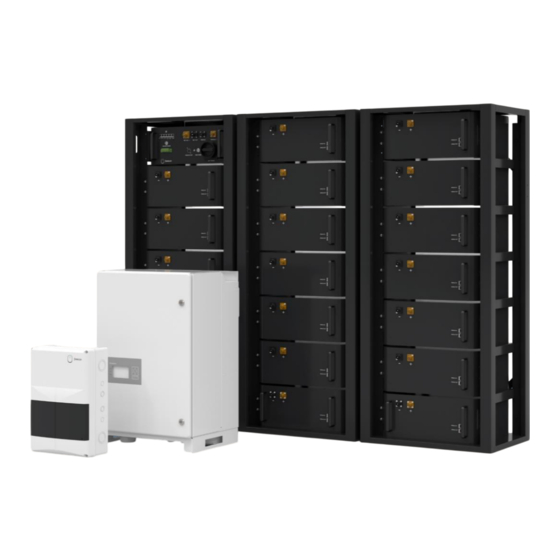
Page 2: System Structure Diagram
Genertor voltage AC generator meter Battery rack FEMS PV inverter 400V/230V Grid 2x35 DC High Voltage RS485 Bus LAN (Ethernet CAT 6) 2x 0,75 LYCY Operator Network Measuring lead transducer Copyright by FENECON GmbH Single-phased representation, not drawn to scale. - Page 3 BMS) is the same as the standard system layout diagram! Battery racks (see previous page – p. 2) 400V/230V Grid Battery racks 2x35 DC High Voltage LAN (Ethernet CAT 6) Copyright by FENECON GmbH Single-phased representation, not drawn to scale.
- Page 4 NH 100A NH 100A standard system layout diagram! (p. 2) Battery inverter FEMS Battery racks 400V/230V Grid 2x35 DC High Voltage LAN (Ethernet CAT 6) 2x 0,75 LYCY Copyright by FENECON GmbH Single-phased representation, not drawn to scale.
- Page 5 System Structure Diagram in case of mutiple inverter installation Battery inverter Battery inverter FEMS Battery racks 400V/230V Grid 2x35 DC High Voltage LAN (Ethernet CAT 6) 2x 0,75 LYCY Copyright by FENECON GmbH Single-phased representation, not drawn to scale.
- Page 6 The installation instructions must be read and understood before installation. Before assembly, note or photograph the serial numbers of the individual components, as these must be documented later at the IBN (in the IBN log or IBN assistant). Copyright by FENECON GmbH...
- Page 7 Assembly KACO inverter Conditions for installation 300 mm The KACO inverter of the Commercial 50 is designed for outdoor and indoor use. In general, when selecting the installation location, pay attention to the protection class, which corresponds to IP65 for the inverter.
- Page 8 3. Mark the position of the drill holes using the recesses in the mount 4. Fasten the wall mount upright to the wall using suitable fastening material (note alignment) Fastening material included in the scope of delivery! Copyright by FENECON GmbH...
- Page 9 Note: lower marking on the housing must stand out over the upper outer contour of the holder > outer contour of holder must be flush with outer contour of housing Copyright by FENECON GmbH...
- Page 10 Mark the position of the FEMS box on the wall using the cutouts for drill holes Mount the box on the wall using suitable fastening material (use a spirit level for help) Mounting material is not included in the scope of delivery. Copyright by FENECON GmbH...
- Page 11 Mount the battery string combiner box on the wall using suitable fastening material (use a spirit level for help) Mounting material is not included in the scope of delivery. *Representation may differ from the received product Copyright by FENECON GmbH...
-
Page 12: Installation Conditions
A distance of 500 mm must be maintained in front of the battery rack. Weight small rack: 40 kg Dimensions (W|D|H) small rack : 625|430|1,471 mm At least 2 people are required to assemble the battery racks. Copyright by FENECON GmbH... - Page 13 2,100|750|1,850 mm Weight: 425 kg More detailed information on the outdoor rack, with regard to assembly and installation, can be found in the separate instructions. These can be found on our website in the download center. Copyright by FENECON GmbH...
- Page 14 Multiple battery racks are grounded to each other with a flat grounding conductor! > included in the scope of delivery Equipotential bonding Copyright by FENECON GmbH...
- Page 15 Dimensions (W|D|H): 180 x 465 x 320 mm Weight: 13.5 kg Submaster BMS Dimensions (W|D|H): 180 x 465 x 320 mm Weight: 12 kg Battery Module Dimensions (W|D|H): 194 x 465 x 380 mm Weight: 37.5 kg Copyright by FENECON GmbH...
- Page 16 For a DC cluster (= several BMS/strings on one inverter + string collection box), a master BMS and a submaster BMS are used. In an AC cluster (= several BMS/strings with several inverters), one master BMS is used per inverter. Copyright by FENECON GmbH...
- Page 17 > Make sure to use the serrated serrated lock washers/contact washers included in the scope of delivery (serration is located on the mounting bracket) → Remove the protective caps from the DC connectors. Keep them for possible disassembly. Copyright by FENECON GmbH...
- Page 18 Wiring within the Rack Hints for wiring the battery racks > Make sure that the plugs snap audibly into place when wiring the DC lines > Unlocking is possible on the side of the plug Copyright by FENECON GmbH...
- Page 19 Connector black/black for connection from master "MODULE OUT" to battery module 1 BMS port "MODULE -" to module 1 (first module (first module below the BMS box) "MODULE IN" below BMS box) port " - " connection Copyright by FENECON GmbH...
- Page 20 DC cable black 250 mm - 25 mm². Connector orange/black for connection between battery modules from terminal " + " to " - ". Communication cable 300 mm RJ45 connectors for connection between battery modules from "MODULE OUT" connector to "MODULE IN". Copyright by FENECON GmbH...
- Page 21 Module 6 Module 20 from "MODULE OUT" to "MODULE IN". > for connection of several racks (from the first to the second > bottom, from the second to the third > top) Last module of the string Copyright by FENECON GmbH...
- Page 22 Connector black/black for connection from BMS Anschluss „MODULE OUT“ zum master BMS port "MODULE -" to module 1 (first Batteriemodul 1 (erstes Modul unterhalb der module below BMS box) port " - " BMS-Box) „MODULE IN“ Copyright by FENECON GmbH...
- Page 23 Module 20 Module 6 "MODULE OUT" to "MODULE IN". > for connection of several racks (from the first to the second > bottom, from the second to the third > top) Last module of the string Copyright by FENECON GmbH...
- Page 24 Resistor Communication cable (5 meter) is included in scope of delivery. gray into PARALLEL OUT port on submaster BMS Communication Ethernet: To connect rack 1 Master BMS port PARALLEL OUT to Submaster BMS port PARALLEL IN. Copyright by FENECON GmbH...
- Page 25 (see separate instructions for installation and configuration of the meter) Communication to inverter (LAN/Ethernet - RJ45) Connection to operator network (LAN – RJ45 – not included in delivery) Supply FEMS (e.g. NYM-I 3x1,5 mm² – AC connection cable not included in delivery) Copyright by FENECON GmbH...
- Page 26 To the master BMS box - 8-pin connector: Pin 4 - Wire no. 1 of FEMS connection box Relay board connection 8 - Pin L To master BMS box - 8-pin connector: Pin 3 - Wire no. 2 of FEMS connection box Relay board connection 8 - Pin NC Copyright by FENECON GmbH...
- Page 27 To the connection "Ethernet 4 (3, 2)" at Pin 3 (Wire No. 2) Pin 4 (Wire No. 1) the switch in the FEMS connection box To the relay board in the FEMS connection box Connection: Wire No.: Copyright by FENECON GmbH...
- Page 28 In case of a separate PE and N connection, the PEN Loosen the Remove cover jumper must be removed. screws Loosen screws L1 L2 L3 Fasten the Remove PEN cover again bridge with the screws L1 L2 L3 Einphasige Darstellung, nicht maßstabsgetreu. Copyright by FENECON GmbH...
- Page 29 DC connection BMS box or string collection box (if installed) - Power Out + DC connection BMS box or string collection box (if installed) - Power Out - Communication FEMS (LAN) Communication to additional inverters AC grid connection (AC connection cable not included in the scope of delivery) Copyright by FENECON GmbH...
- Page 30 Connection of KACO Inverter with Master BMS Box and FEMS Box 160 A Grid connection DC-cable (5 meter) are included in scope of delivery. N/PEN LAN – RJ45 "Ethernet 6" connection on the switch in the FEMS box Copyright by FENECON GmbH...
- Page 31 Connection of the Battery String Combiner Box to Inverter in case a submaster BMS is installed 125 A Press 35 mm² ferrules onto 160 A the DC cable > included in delivery Grid connections N/PEN DC-cable (5 meter) are included in scope of delivery. Copyright by FENECON GmbH...
- Page 32 Connection of the Battery String Combiner Box to BMS boxes in case a submaster BMS is installed Press ring cable lugs 35 mm²/ M10 onto the DC cable > included in delivery 125 A DC-cable (5 meter) are included in scope of delivery. Copyright by FENECON GmbH...
- Page 33 AC generator meters are not part of the scope of delivery! However, for a correct display of consumption and generation in the online monitoring, the generation must be measured! Attention: The transformer ratio (secondary current) in this case is 5. Copyright by FENECON GmbH...
- Page 34 However, for a correct display of consumption and generation in the online monitoring, the generation must be measured! Attention: The transformer ratio (secondary current) can be 1 or 5 for this meter! Copyright by FENECON GmbH...
- Page 35 To switch on, press the "Power" button on the master BMS box and then the "Master Power" button > If no errors occur in the system, lamps A, B and C light up green after a certain time Copyright by FENECON GmbH...
- Page 36 1. Pull the patch cable out of the "INTERNAL" connector on the master BMS 2. Take a patch cable and connect the "INTERNAL" connector on the master BMS to a PC/laptop. Copyright by FENECON GmbH...
- Page 37 4. Click on the "Change adapter options" button. 5. Now there are different Ethernet connections to choose from. Select here the connection to the master BMS with a double click. (No "x" is visible at the corresponding Ethernet connection). Copyright by FENECON GmbH...
- Page 38 In this window the line "Internet protocol. Version 4 (TCP/IPv4)" must be selected. Again a window opens, here the selection option "Use the following IP address" must be selected. The following number is now entered in the "IP address" field: "192.168.0.30". These steps are each confirmed with "OK". Copyright by FENECON GmbH...
- Page 39 7. Open now any browser. 8. Enter the following IP address in the adress bar: 192.168.0.7 9. In the field that appears, you must enter "admin" for the username AND the password. 10. Then click "Log in". Copyright by FENECON GmbH...
- Page 40 12. In the line "Work Mode" the setting "TCP Server" must be selected. (By default, "TCP Client" is usually selected.) 13. This setting must be stored with "Save". 14. Then click " Restart Module". Copyright by FENECON GmbH...
- Page 41 Finally, the connection between Master BMS and laptop/PC must be disconnected again. In addition, the connection between the Master BMS and the FEMS box must be re- established. To do this, reconnect the previously disconnected cable: INTERNAL to FEMS-Box Copyright by FENECON GmbH...
- Page 42 1. To do this, select the "Local IP Config" tab on the left side of the page. 2. Make sure that the "Static IP" is consecutive. First Master BMS: 192.168.0.7 Second Master BMS: 192.168.0.8 Third Master BMS: 192.168.0.9 Copyright by FENECON GmbH...
- Page 43 To return to the last selected menu item, press the ESC key. Insert the required settings. In the last menu item, press the Enter key. Does not replace the operating instructions of the KACO blueplanet gridsave 50.0TL3-S Copyright by FENECON GmbH...
- Page 44 Perform firmware update see blueplanet gridsave 50.0 TL3 Software Update Guide V5.59 In Austria the firmware update is mandatory - contact your FENECON contact person for the update file. blueplanet The USB interface is located on the communication board inside the housing door.
- Page 45 Quick configuration network - inverter KACO Start interface Use the right key to enter the main menu to make settings. blueplanet Uhrzeit Datum 0.00 0kWh 0kWh Does not replace the operating instructions of the KACO blueplanet gridsave 50.0TL3-S Copyright by FENECON GmbH...
- Page 46 Ges. Energie def. Logging-Intervall Subnetzmaske Logging-Intervall Informationen Logdaten-Backup Logdaten-Backup Gateway Hersteller Display DNS-Server Display Datum & Uhrzeit Datum & Uhrzeit Webserver Netzwerk Netzwerk Modbus TCP Does not replace the operating instructions of the KACO blueplanet gridsave 50.0TL3-S Copyright by FENECON GmbH...
- Page 47 Hauptmenü Hauptmenü DHCP IP-Adresse DHCP DHCP IP-Adresse IP-Adresse Subnetzmaske Subnetzmaske Gateway Gateway 010.004.000.010 DNS-Server DNS-Server Webserver Webserver Modbus TCP Modbus TCP Does not replace the operating instructions of the KACO blueplanet gridsave 50.0TL3-S Copyright by FENECON GmbH...
- Page 48 IP-Adresse IP-Adresse DHCP DHCP IP-Adresse IP-Adresse Subnetzmaske Subnetzmaske Gateway Gateway 010.004.000.010 010.004.000.011 DNS-Server DNS-Server Webserver Webserver Modbus TCP Modbus TCP Inverter 1 Inverter 2 Does not replace the operating instructions of the KACO blueplanet gridsave 50.0TL3-S Copyright by FENECON GmbH...
- Page 49 Hauptmenü Subnetzmaske DHCP DHCP Betriebsmodus IP-Adresse IP-Adresse Port Subnetzmaske Subnetzmaske Fern-Konfiguration Gateway Gateway Fern- Update 255.255.000.000 DNS-Server DNS-Server Webserver Webserver Modbus TCP Modbus TCP Does not replace the operating instructions of the KACO blueplanet gridsave 50.0TL3-S Copyright by FENECON GmbH...
-
Page 50: Remote Configuration
Quick configuration network - inverter KACO Remote configuration confirm with Remote update confirm with blueplanet blueplanet Hauptmenü Hauptmenü Fern-Konfiguration Fern-Update Betriebsmodus Betriebsmodus Port Port Fern-Konfiguration Fern-Konfiguration Fern-Update Fern-Update Does not replace the operating instructions of the KACO blueplanet gridsave 50.0TL3-S Copyright by FENECON GmbH... - Page 51 Quick configuration network - inverter KACO return to start display (graphic display) blueplanet Datum Uhrzeit 10.00 10kWh 10kWh Ersetzt nicht die Betriebsanleitung vom KACO blueplanet gridsave 50.0TL3-S Copyright by FENECON GmbH...
-
Page 52: Initial Setup
During the IBN, it is mandatory to fill out the IBN protocol and send If you use other additional apps (such as heating element, EV it to FENECON within 30 days or the automatically created IBN charging stations), please also contact our service team. - Page 53 IBN and sent to the customer. NOTE NOTE If no installer account has been created yet, this can be done After entering the installation key, directly on the login page follow the steps of the configuration. Copyright by FENECON GmbH...
-
Page 54: Online Monitoring
NOTE Once the battery and the configuration of the installed meters are successfully completed, the appropriate values are displayed in the online monitoring. Copyright by FENECON GmbH... - Page 55 Notes ______________________________________________________________________________________________________________________________ ______________________________________________________________________________________________________________________________ ______________________________________________________________________________________________________________________________ ______________________________________________________________________________________________________________________________ ______________________________________________________________________________________________________________________________ ______________________________________________________________________________________________________________________________ ______________________________________________________________________________________________________________________________ ______________________________________________________________________________________________________________________________ ______________________________________________________________________________________________________________________________ ______________________________________________________________________________________________________________________________ ______________________________________________________________________________________________________________________________ ______________________________________________________________________________________________________________________________ ______________________________________________________________________________________________________________________________ Copyright by FENECON GmbH...
Need help?
Do you have a question about the Commercial 50 and is the answer not in the manual?
Questions and answers