Table of Contents

Summary of Contents for J&M Storm Tracker
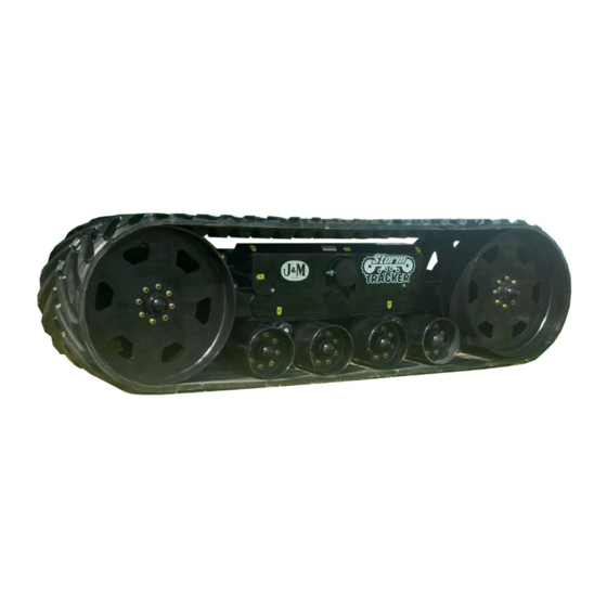
- Page 1 O P E R A T O R’ S M A N U A L Storm Tracker Track System FRONT J. & M. Manufacturing Co., Inc. P.O. Box 547 Fort Recovery, OH 45846 Phone: (419) 375 2376 Fax: (419) 375-2708 E-mail: sales@jm-inc.com Website: www.jm-inc.com...
- Page 2 ealer TO THE DEALER: Read manual instructions and safety rules. Make sure all items on the Dealer’s Pre-Delivery and Delivery Check Lists in the Operator’s Manual are completed before releasing equipment to the owner. The dealer must complete the Warranty Registration Card attached to the front inside cover of this manual and return to J. & M. Mfg.
-
Page 3: Eneral I Nformation
TITLE pecificaTionS Specifications Track Width 36” Idler Width (effective) 36” Overall Length (A) 146” Idler Diameter 36” Roller Diameter 12 3/4” Wheel Base (B) 105” Main Pivot Pin Diameter 6” Dia (4140) Track Length 324” Track Height (C) 42” Track Width 36”... - Page 4 eneral nforTmaTion BOLT TORQUE CHART Always tighten hardware to these values unless a different torque or tightening procedure is listed for a specif- ic application. Fasteners must always be replaced with the same grade as specified in the manual parts list. Always use the proper tool for tightening hardware.
- Page 5 afeTy uleS ATTENTION! BECOME ALERT! YOUR SAFETY IS INVOLVED! Safety is a primary concern in the design and manufacture of our products. Unfortunately, our efforts to pro- vide safe equipment can be erased by an operator’s single careless act. In addition, hazard control and accident prevention are dependent upon the awareness, concern, judgment, and proper training of personnel involved in the operation, transport, maintenance and storage of equipment.
- Page 6 Service OPERATING INSTRUCTIONS IMPORTANT: To maximize the life of your track system, it is recommended that wide turns be consistently made whenever possible. Turning in a circle that is THREE TIMES the overall length of the tractor and track unit will reduce premature wear on the belt and undercarriage. Lubrication Service Schedule IMPORTANT: Your Track System has grease fittings at all critical points.
-
Page 7: Routine Maintenance
Routine Maintenance WARNING: When Servicing The Track System, Be Certain All Power To Grain Cart Is Shut Off. Repack the wheel bearings at least once a year. Use Bearing Gard MK1 or equivalent lubricant. Also check the seal for wear and replace if necessary. Check the track system periodically for cracks in welds and for other structural damage. -
Page 8: Track Alignment
Service AIR BAG REPLACEMENT If replacement of the track tension air springs become necessary, the following steps must be performed: 1. Slowly release the air pressure from the rubber bladder. 2. Remove the bolts that hold the air spring in place and remove the air spring. 3. -
Page 9: Belt Inspection
Service BELT INSPECTION The rubber track is composed of several layers of cable, similar to the cables used in automotive tires. The most important set of cables are located about 8 mm (0.3 in.) beneath the inside surface of the track. This set of ca- bles, called zero degree cables, withstands track tension. -
Page 10: Installation
Installation Step 1 - Install both spindles. Use (2) 1” x 9” Hex Bolts and (2) 1” Centerlock Hex Nuts to attach the spindles to the cart. Next slip the 6” Rubber O-ring onto the spindle. Step 2 - Use an overhead hoist to pick up the grain cart. Use a hoist and chains that are rated for the specific weights. - Page 11 Installation Step 4 - Slide the tracks onto the spindle. Step 5 - Slip the 6” Rubber O-Ring onto the spindle, pushing it up against the track spindle. Step 6 - Install the Track Spindle Collar. Use a 1” x 9” Hex Bolt and a 1” Centerlock Hex Nut to fasten the Collar to the Spindle.
- Page 12 Parts...
- Page 13 Parts Description Part. No. 2-1/2” ID Bronze Bushing JM0016841 Bogie Wheel Swivel Weldment JM0020256 1”-8 Gr5 Z Centerlock Hex Nut JM0002149 1”-8 x 5-1/2” Gr5 Z Hex Bolt JM0002110 Double End Spindle 3” X 29 5/8” JM0020287 30087 Seal JM0020311 G848 Small Cone Bearing JM0020305 1-1/4-12 Gr5 Z Castle Hex Nut...
- Page 14 Parts TITLE...
- Page 15 Parts TITLE Part. No. Description JM0020273 Track Carriage Beam Frame Weldment JM0020350 6” ID Bronze Bushing JM0016687 1”-8 X 4-1/2” Gr5 Z Hex Bolt JM0002110 1”-8 X 5-1/2” Gr5 Z Hex Bolt JM0020309 G848 Hub Cpt. 8000# with Studs Lugs and Races JM0020287 Double End Spindle 3"...
- Page 16 Notes DATE NOTE...
Need help?
Do you have a question about the Storm Tracker and is the answer not in the manual?
Questions and answers