Table of Contents
Advertisement
Quick Links
Advertisement
Table of Contents

Summary of Contents for Lec L-1000
- Page 1 L-1000 Operation Manual (Optical Fiber Type) Ver. 1.16PE...
-
Page 2: Table Of Contents
Table of contents Table of contents ........................1 1. When the product arrives, please check................3 1.1 Checking the body and accessories................3 1.2 Check of product specification ..................3 2. Part name ......................... 4 2.1 Front panel ........................4 2.2 Rear panel ........................ - Page 3 12.3.3 Alarm operation mode selection ..............31 12.3.4 Request ......................31 12.4 Error message ......................31 13. Troubleshooting ......................33 14. Emissivity table ......................34 15. Specification ......................... 35 16. L-1000 outside-of-the-body type size, the Panel cut size ..........37...
-
Page 4: When The Product Arrives, Please Check
Introduction..Thank you very much for purchasing our infrared thermometer "L-1000" lately. "L-1000" is the optical fiber type noncontact thermometer which smashed the expensive image of the conventional infrared thermometer and harnessed the price united with the visitor's needs, and high technology. The optical fiber system condenses the infrared rays emitted from the object by the sensor head, and infrared rays spread using the optical fiber and detect the infrared rays by the main part. -
Page 5: Part Name
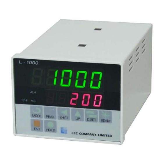
2. Part name Display The measured value and the 2.1 Front panel preset value are displayed. Operation lamp The operating state is displayed. Operation key Refer to the following table for each function. Mark Name Function The contents of the setting are checked or the preset MODE value to change is called. -
Page 6: Rear Panel
2.2 Rear panel Power supply terminal (Left end: #1) connector for measurement Connector for serial communications Connector for the beams Input/output terminal (left end: #1) Connector / Terminal Specification AC 85-246[V] Power supply terminal (1-2pin) Power supply terminal (3pin) Serial communications (option) D-Sub 9pin Optical fiber is connected. -
Page 7: Type Of Sensor Head
3. Type of sensor head (Area and distance which can be measured) There are the fixed focus type and the movable focal type of sensor heads. Case of 140 ~ 500 ℃, measurement area is twice. -
Page 8: Series
3.1 SH-25 Series... -
Page 9: Series
3.2 SH-7 Series... -
Page 10: Value Head
3.3 Value head Dimensional outline drawing Measurement area and distance... -
Page 11: Type Of Optical Fiber
3.4 Type of optical fiber Fiber kind Spot form Standard With the stainless steel protective tube Measurement / beam Y type composite 4. Preparation before operation The power supply and the wiring of each output It is cautious of the arrangement of the terminal enough, and wire connection is carried out to it. -
Page 12: Wiring And Installation
Since there are black (sensor head side) and red (converter side) in an optical fiber, it connects so that it may not mistake. With Y type fiber, measurement is impossible in the beam side. Setup of sampling speed, emissivity, and the output The various preset values are changed according to measurement conditions or environment. - Page 13 When removing the cap from the optical fiber cable, the knurled portion is certainly had and removed. (Removing the cap with the portion of the back resin from the tip of the optical fiber cable has the danger of damaging the cable.)
-
Page 14: Wiring On Main Part Of Infrared Thermometer
5.3 Wiring on main part of infrared thermometer A.Power supply terminal AC 85 - 246 [V] is connected to ①-②. Earth wire is connected to ③. B.Input/output terminal The terminal of ① and ② is the output of AL-L. In the case of the open collector, polarity is mistaken at the time of wiring -- be careful for there to be nothing. -
Page 15: Connection Method Of Power Supply Terminal
Connection diagram Example of wiring of the power supply Example of connection of RS-232 Example of wiring of the input/output Example of connection of the optical terminal fiber 5.4 Connection method of power supply terminal Terminal screw of the power supply terminal is M3. The suiting pressure terminal becomes below A= 6[mm] for M3. -
Page 16: Connection Method Of Input/Output Terminal
5.5 Connection method of input/output terminal It can connect without using the pressure terminal. Moreover, the input/output terminal can desorb disconnection the portion of the terminal, and when connecting with the terminal, if the terminal is removed from the main part, it can do connection easily. Connection-wire range: AWG 24-14 (twist line) Length: 7 [mm] which removes the electric wire 5.6 Connection method of optical fiber... -
Page 17: Y Type (F05Y)
The height of a fiber connector is inserted in accordance with the slot in the main part connector upper part, and Laurette is transferred and it fixes. ※ Please keep in mind that there is a possibility that a pin may bend if Laurette is transferred in the state where the slot does not suit a pin. -
Page 18: Check Method Of Measurement Place
6. Check method of measurement place * When measurement temperature must check the high temperature case and the direct measurement place, please be sure to use the dark filter (please do not see directly) and to protect the eyes. It is made easy to cool the temperature of the measurement thing to the room temperature once and to check, when the temperature of the measurement thing is high and the check is difficult. -
Page 19: In Case Of Movable Focus
6.2.2 In case of movable focus Since the length of the movable part determines the focal length arbitrarily, the movable part is adjusted using beam so that the beam spot can be seen clearly. The attached hexagonal wrench is used and the screw is loosened. The movable part (cylindrical object lens) is moved, and it adjusts so that the image of beam may appear clearly. -
Page 20: Peak Operation Mode (Highest Measured Value)
7. Peak operation mode (Highest measured value) If the PEAK key is pressed, it will become the mode which continues displaying the measured highest temperature. In order to cancel, if the PEAK key is pressed once again, it will return to the usual measurement mode. -
Page 21: Function In Which Set Up Time Updates Peak Temperature
7.2 Function in which set up time updates peak temperature If the set period passes, peak temperature will be canceled and keep temperature will be updated. Time to pass is also reset when the peak value is updated within the set-up time. -
Page 22: Hold Mode
8. Hold mode The measured value of the moment that the HOLD key is pressed is displayed until the function is canceled. Once again, a push on the HOLD key will cancel the function. Display data is not updated even if the temperature of the measurement thing changes. -
Page 23: Operation Of The Alarm Hysteresis
9.2 Operation of the alarm hysteresis You can set the hysteresis width of the alarm operation. Than the alarm set point, hysteresis width is set on both sides of the cold side and hot side. In addition, the “set” point to "more than the set point, or less than" point the alarm will be made to the operation of the ON, the alarm is turned OFF 10. -
Page 24: Various Setting
11. Various setting L-1000 will go into the measurement state by the pattern which was being used last time, if the power supply is switched on. * It is in the state with effective Pn01 and key lock at the time of factory shipments. -
Page 25: Alarm High Setup (Ah)
11.3 Alarm high setup (AH) The threshold value of the comparator output is set up. It is set to ON by temperature >=AH, and is come by off at > (AH-3) temperature. Setting range: High- Low 1 [℃] step Operation: SHIFT= beam movement, UP= numerical value rise, ENT= determination In the ERROR display, please redo with the right value. -
Page 26: Selection Of Operation Mode Alarm (Rm)
11.6 Selection of operation mode Alarm (RM) I want the alarm action. Setting range:AB、BA、AA、BB Operation: UP=switch, ENT=Decision The setting is changed and appears SET 11.7 Peak cancellation time setup (PT) Time to cancel and update the highest temperature display of the peak operation mode is set up. -
Page 27: Average Value Filter Setup (Av)
11.10 Average value filter setup (AV) The intensity of the average value filter is set up. The invalidity and 10 are the maximum in 0. Setting range: 0-10 1 step Operation: UP= numerical value rise, ENT= determination A display of SET will change the contents of the setting. -
Page 28: Selection (Stop) Of Stop Bit Length
11.14 Selection (STOP) of stop bit length The stop bit length of the communication format of RS232C is chosen. Setting range: 1 bit, 2 bits Operation: UP= Switch and it is ENT= determination. A display of SET will change the contents of the setting. -
Page 29: Serial Communication (Rs-232 Conformity)
12. Serial communication (RS-232 conformity) All the command forms of this machine serve as the ASCII code. Communications protocol pin assignment becomes as follows. method Synchronous full-duplex data length 7 bits and 8 bits Selection Stop bit 1 bit and 2 bits Selection Parity bit Nothing Fixation... -
Page 30: Command List
12.2 Command list Command Explanation Peak operation mode OFF Peak operation mode ON Acquisition of an ON/OFF state of the peak operation mode 得(p0 :OFF、p1:ON) HOLD mode OFF HOLD mode ON Acquisition of an ON/OFF state in HOLD mode得(h0:OFF、h1: The number of the pattern is changed. The present number of the pattern is acquired. -
Page 31: The Example Of The Command
12.3 The example of the command 12.3.1 Mode Example: Hold OFF Example::Gets the state of the peak Example p: The peak, h:hold, 0:OFF, 1:ON, ? : it is the combination of the acquisition of the state. reply data -- the same . 12.3.2 The various preset values Example: Set emittance as 0.9. -
Page 32: Alarm Operation Mode Selection
(continuation) command is sent once again. The request (single shot) command replies the present temperature only once. 。 12.4 Error message The error message of L-1000 is the three following kinds. Command not found: When the command is mistaken Buffer overflow:... - Page 33 Error: When having separated from the setting range...
-
Page 34: Troubleshooting
13. Troubleshooting Condition Cause Correspondence The power supply Wire connection mistake It connects with the right is not turned on. Slack of the contact position. button After certainly turning OFF the power supply, the screw of the terminal, etc. are bound tight firmly. -
Page 35: Emissivity Table
14. Emissivity table Emissivity Temperat Substance Polished surface Rough surface Non-oxidatio [℃] Zinc 1-oxidation 20-400 2-oxidation Alumina 1500 0.2-0.4 Non-oxidation 0.05 0.25 1-oxidation 25-600 Aluminum 2-oxidation Fusion ― ― Gold Non-oxidation 100-1000 0.04 0.15 100-1200 0.25 Ceramics 1500 1800 Non-oxidation 0.35 0.35 1-oxidation... -
Page 36: Specification
15. Specification L-1000 L-1000-S TYPE Temperature 140-1300[℃] 600-3000[℃] range Element InGaAs wavelength 1.6[μm] 0.9[μm] accuracy ±1[%] ε=1.0 Reproducibility ±1[℃] +1[digit] 1[℃] Resolution Display part 7segLEDCharacter quantity14.6[mm] Preset 7segLEDCharacter quantity10.1[mm] Response time 0.01[sec] 表示部 Emissivity 0.050-1.200 setting range Setting Front panel key operation Analog output DC0-10[V],4-20[mA],<500[Ω]... - Page 37 Outside 96×72×165 [mm] dimension Weight 1.5[kg] (L-1000 Only) * It is forbidden without notice to reproduce. (This specification may be changed without the preliminary announcement for improvement.)
-
Page 38: L-1000 Outside-Of-The-Body Type Size, The Panel Cut Size
16. L-1000 outside-of-the-body type size, the Panel cut size...
Need help?
Do you have a question about the L-1000 and is the answer not in the manual?
Questions and answers