Table of Contents
Advertisement
Quick Links
Advertisement
Table of Contents

Related Manuals for EPH Controls A17


Summary of Contents for EPH Controls A17
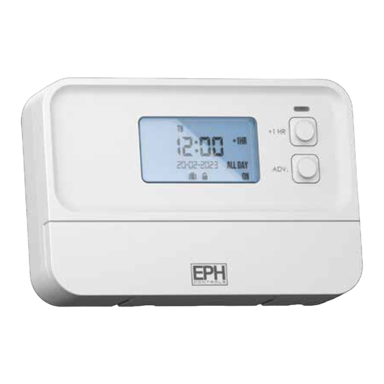
- Page 1 1 Zone Timeswitch Installation and Operation Guide...
-
Page 2: Table Of Contents
Table of contents Installation Instructions Factory Default Settings Frost Protection Specifications Quick introduction to your A17 Timeswitch Wiring diagram Mounting & Installation Operating Instructions LCD Symbol Description Button Description Resetting the Timesitch Keypad lock and unlock Setting the date and time... - Page 3 Copy Function Reviewing the program settings Boost function Advance function Holiday mode Backlight mode selection PIN Function Service Interval...
-
Page 4: Installation Instructions
p1 Zone Timeswitch Installation Instructions... -
Page 5: Factory Default Settings
Frost protection is built into this timeswitch. It is pre fixed at 5°C and is not adjustable. It will only be activated when the timeswitch is in the OFF mode and the room temperature falls below 5°C. EPH Controls Ltd. -
Page 6: Specifications
Specifications Power Supply: 200 - 240 Vac, 50-60 Hz, 8 VA Ambient Temperature: 0 … 45˚C Relative Humidity Range: 5-95% RH Contact Rating: 250VAC 3(1)A Program Memory Backup: 3 months Battery: LIR2032 Backlight: Blue IP Rating: IP20 Backplate: British System Standard Pollution Degree: Pollution Degree 2 Rated Impluse Voltage:... -
Page 7: Quick Introduction To Your A17 Timeswitch
P2 and P3. See Page 19 for instructions on how to adjust the program settings. On the LCD screen of your A17 you can see what mode the timeswitch is currently in. For ‘Mode Selection’ please see page 18 for further explanation. -
Page 8: Wiring Diagram
Wiring diagram 200-240V~ 50/60Hz Terminal Connections Switching Options Mains Switching Earth - Link L to 1. Neutral Low Voltage Switching Live - Remove the external controls link from the boiler PCB. Common Connection - Connect 1 and 4 to these terminals. N/C Normally Closed Connection N/O Normally Open Connection... -
Page 9: Mounting & Installation
ƒ described in this section. Before commencing installation, the timeswitch must be first disconnected from the ƒ mains. This timeswitch can be mounted in the following ways: 1) Surface mounted 2) Mounted to a recessed conduit box EPH Controls Ltd. - Page 10 Mounting & Installation (Continued) Remove the timeswitch from its packaging. Choose a mounting location for the timeswitch: - Mount the timeswitch 1.5 metres above the floor level. - Prevent direct exposure to sunlight or other heating / cooling sources. Use a philips screwdriver to loosen the screws of the backplate on the bottom of the timeswitch.
- Page 11 EPH Controls Ltd.
-
Page 12: Operating Instructions
1 Zone Timeswitch Operating Instructions... -
Page 13: Lcd Symbol Description
Displays auto mode is activated. [2] Displays current time. Displays all day mode. [3] Displays day of the week. Displays off & on mode. [4] Displays advance function. Displays when keypad is locked. [5] +1hr function. [10] Displays holiday mode. [10] EPH Controls Ltd. -
Page 14: Button Description
Button Description +1HR button Advance button – button button OK button Select button Reset button Holiday mode Clock set / Run / Program Set + button Advance button Reset button OK button – button Holiday mode – +1HR button Select button Clock set / Run Program Set... -
Page 15: Resetting The Timesitch
To lock the keypad, press and hold the buttons for 5 seconds. will appear on the screen. The keypad is now locked. To unlock the keypad, press and hold the buttons for 5 seconds. will disappear from the screen. The keypad is now unlocked. EPH Controls Ltd. -
Page 16: Setting The Date And Time
Setting the date and time Lower the flap on the front of the unit. Move the selector switch to the CLOCK SET position. Press the buttons to adjust the day. Press the button. – Press the buttons to adjust the month. Press the button. -
Page 17: Factory Program Setting
P2 ON P2 OFF P3 ON P3 OFF All 7 days 06:30 08:30 12:00 12:00 16:30 22:30 24 Hour P1 ON P1 OFF P2 ON P2 OFF P3 ON P3 OFF Everyday 06:30 08:30 12:00 12:00 16:30 22:30 EPH Controls Ltd. -
Page 18: Mode Selection
Mode selection There are 4 modes availablefor selection. AUTO The timeswitch operates 3 ‘ON/OFF’ periods per day. (P1, P2, P3) ALL DAY The timeswitch operates 1’ON/OFF’ period per day. This operates from the first ON time to the third OFF time. The timeswitch is permanently ‘ON’... -
Page 19: Adjust The Program Setting
P1 OFF time. – Press the button. Repeat this process to adjust the ON & OFF times for P2 & P3. When completed, move the selector switch to the RUN position. CLOCK PROG EPH Controls Ltd. -
Page 20: Copy Function
Copy Function Copy function may only be used if the timeswitch is in the 7d mode. (See page 16 to select 7d mode) Lower the flap on the front of the timeswitch. Move the selector switch to the PROG SET position. -
Page 21: Reviewing The Program Settings
When a boost period has ended or has been cancelled, the timeswitch will return to the mode that was previously active prior to the boost. Note: A Boost cannot be applied while in the ON or Holiday Mode. EPH Controls Ltd. -
Page 22: Advance Function
Advance function This function allows the user to bring forward the next switching time. If the timeswitch is currently timed to be OFF and the ADV pressed, the zone will be switched ON until the end of the next switching time. If the zone is currently timed to be ON and the ADV is pressed, the zone will be switched OFF until the end of the next switching time. -
Page 23: Holiday Mode
– Press the button. The timeswitch is now switched OFF until the holiday period ends. To cancel the holiday press . The timeswitch will return to normal operation when a holiday is finished or cancelled. EPH Controls Ltd. -
Page 24: Backlight Mode Selection
Backlight mode selection There are two settings for selection. The factory default setting is ON. The backlight is permanently ON. AUTO On pressing any button the backlight stays on for 10 seconds. To adjust the backlight setting, lower the flap on the front of the unit. Ensure the selector switch is in the RUN position. -
Page 25: Pin Function
PIN is set, press . Press to set the value from 0 to 9 for the first digit. Press to move to – the next PIN digit. When the last digit of the PIN is set, Press EPH Controls Ltd. - Page 26 PIN Function (Continued) The PIN is now verified ‘OP:01’ will appear on the screen. Press to select between OP:01 and OP:02. Press confrim PIN option – and the PIN lock is activated. If the verification PIN is entered incorrectly the user is brought back to the menu.
-
Page 27: Service Interval
When the Service Interval is activated ‘SErv’ will appear on the screen which will alert the user that their annual boiler service is due. For details on how to enable or disable the Service Interval, please contact customer service. EPH Controls Ltd. - Page 28 EPH Controls IE technical@ephcontrols.com www.ephcontrols.com/contact-us T +353 21 471 8440 EPH Controls UK technical@ephcontrols.co.uk www.ephcontrols.co.uk/contact-us T +44 1933 322 072...
Need help?
Do you have a question about the A17 and is the answer not in the manual?
Questions and answers