Advertisement
Quick Links
Advertisement

Summary of Contents for Donaldson BOFA DustPRO 50
- Page 1 DustPRO 50 USER MANUAL V2 Jan 16...
-
Page 2: Table Of Contents
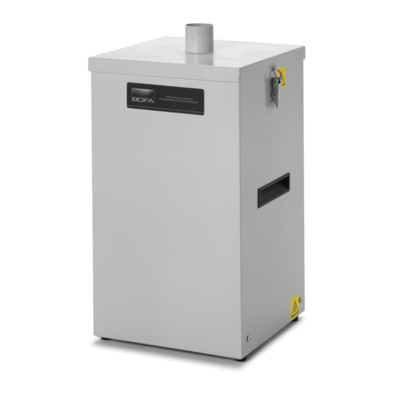
Contents Overview of your DP50 (front) Overview of your DP50 (back) Important safety notes Safety labels Unpacking and unit placement Fume capture methods Connecting to power supply Optional added features Turning extractor on Cleaning the unit Filter replacement Consumable spares & filter disposal DustPRO 50 specifications... - Page 3 Overview Air inlet Clips Carry handles Feet...
- Page 4 Overview Signal cable outlet (optional) Air outlet/motor cooling Main isolation switch Mains inlet Override switch (optional)
-
Page 5: Important Safety Notes
Important Safety Instructions To reduce the risk of fire, electric shock or injury: Always isolate the system from the mains power supply before removing the pump/motor access panel. 2. Use only as described in this manual. Connect the system to a properly grounded outlet. Important safety notes Concerning symbols used on the extraction unit and referred Dangers to eyes, breathing and skin... - Page 6 Serial Number Label Safety Instructions Location: Next to mains inlet. Meaning: This label contains a variety of information about the extraction unit, including. Warning and Information labels The following listing details labels used on your DP50 • Company name, Address & Contact number extraction unit.
- Page 7 Before Installation Packaging Removal & Unit Placement Before installation, check the extraction unit for damage. All packaging must be removed before the unit is connected to the power supply. Please read all instructions in this manual before using this extractor. 1.
-
Page 8: Fume Capture Methods
Flexible Arm & Nozzle Extraction (Optional Kits) Installation The stay put arm should be mounted as close as possible to the marking point using the horseshoe clips. Unscrew the push fit connector from the other side of the flexible hose. Cut the flexible hose to suit the distance back to the extractor connection and push onto the extractor inlet. -
Page 9: Connecting To Power Supply
Installation Specification DP50 Dimensions: Height 635mm Depth 290mm Width 290mm Weight: 23kg (50lbs) Voltage: 115-230V Frequency: 50/60Hz Full load current: 230V:2.8A 115V: 6.0A Power: 230V:400w 115V:500w Capacity: 80m³h (47CFM) Connection to Power Supply Please follow the above specification when selecting the power supply outlet for the extraction system, ensure the power supply is suitable before connecting the DP50 system. -
Page 10: Optional Added Features
Installation The operating voltage for this signal is between 12 & 24VDC. Only voltages within this range should be connected. Voltages connected outside of this range may cause irreversible damage to the internal control PCB. Red cable = V+ Black cable = V- Optional added features When the extractor is provided with the correct DC voltage The DP50 can be configured to suit customer specification. - Page 11 Operation Turning extraction unit On The DustPRO50 features a fused IEC inlet for the mains cable as well as a main isolation switch. The unit can be powered on and off by pressing the red rocker switch to the right hand side. Main Isolation Switch Mains Inlet Fuse Compartment...
-
Page 12: Cleaning The Unit
no longer removes fume efficiently. Maintenance All filters are tested to BS3928. A certificate of conformity for each filter is available on request. It is recommended that a spare set of filters are kept on site to avoid prolonged unit unavailability. Part numbers for replacement filters can be found on the filters fitted in your system. -
Page 13: Filter Replacement
Maintenance Filter Replacement The DustPRO 50 uses one polyester bag filter. This should be replaced when the extraction unit no longer removes particulate effectively. To remove and replace the filter, follow the instructions below. To remove and replace the combined filter follow the procedure detailed below. - Page 14 Filter disposal Replacement Parts The combined filter is manufactured from non-toxic materials. Filters are not re-usable, cleaning used filters is not recommended. The method of disposal of the used filters depends on the material deposited on them. For your guidance Consumable Spares Deposit Comment...
- Page 15 System Specification Unit: DP50 Capacity: 80 m³h (47 CFM) Weight: 23kg (50lbs) Motor: Centrifugal Fan Output: 400w (600w) Electrical supply: 115/230V Hertz: 50/60Hz Full Load Current: 230v: 2.8A 115v:6A Noise Level: Below 63db (at typical operating speed) Size: Metric Imperial (mm) (inches) Height...
- Page 16 Contact Information BOFA Headquarters 19-20 Balena Close Creekmoor industrial Estate Poole Dorset BH17 7DU Phone: +44 (0) 1202 699 444 BOFA Americas 303 S.Madison Street Staunton Illnois 62088 Phone: +1 (618) 205 5007 BOFA International GmbH Sudring 62 D-21465 Wentorf bei Hamburg Germany Phone: +49 (0) 40 7393735-15...
Need help?
Do you have a question about the BOFA DustPRO 50 and is the answer not in the manual?
Questions and answers