
Summary of Contents for dtp CrossPoint 4K Series
- Page 1 DTP CrossPoint 4K Series Scaling Presentation Matrix Switchers User Guide Matrix Switchers 68-2368-02, Rev. L 03 24...
- Page 2 Safety Instructions Safety Instructions • English Instructions de sécurité • Français AVERTISSEMENT : Ce pictogramme, , lorsqu’il est utilisé sur le WARNING: This symbol, , when used on the product, is intended to produit, signale à l’utilisateur la présence à l’intérieur du boîtier du produit alert the user of the presence of uninsulated dangerous voltage within the d’une tension électrique dangereuse susceptible de provoquer un choc product’s enclosure that may present a risk of electric shock.
- Page 3 Registered Trademarks ( ® Extron, Cable Cubby, ControlScript, CrossPoint, DTP, eBUS, EDID Manager, EDID Minder, eLink, Everlast, Flat Field, FlexOS, Glitch Free, Global Configurator, Global Scripter, GlobalViewer, Hideaway, HyperLane, IP Intercom, IP Link, Key Minder, LinkLicense, LockIt, MediaLink, MediaPort, NAV, NetPA, PlenumVault, PoleVault, PowerCage, PURE3, Quantum, ShareLink, Show Me, SoundField, SpeedMount, SpeedSwitch,...
- Page 4 FCC Class A Notice This equipment has been tested and found to comply with the limits for a Class A digital device, pursuant to part 15 of the FCC rules. The Class A limits provide reasonable protection against harmful interference when the equipment is operated in a commercial environment.
- Page 5 Conventions Used in this Guide Notifications The following notifications are used in this guide: ATTENTION: • Risk of property damage. • Risque de dommages matériels. NOTE: A note draws attention to important information. TIP: A tip provides a suggestion to make working with the application easier. Software Commands Commands are written in the fonts shown here: ^AR Merge Scene,,0p1 scene 1,1 ^B 51 ^W^C.0...
-
Page 7: Table Of Contents
Making Ties ............32 Viewing the Configuration ......... 36 Recalling Presets ..........38 Assigning and Unassigning Logos ....39 Configuring the Input Audio ....... 42 Configuring the TP Insertion Ports ....43 Selecting the Remote Port Baud Rate ....44 Background Illumination ........44 DTP CrossPoint 4K Series Matrix Switchers • Contents... - Page 8 Making Labels from Paper Templates .... 173 Setting the Mic Input and Mic Mix-point Installing Labels in the Buttons ....... 173 Levels ............144 Button Label Blanks ........174 Adjusting the Post-matrix Trim ......144 DTP CrossPoint 4K Series Matrix Switchers • Contents viii...
-
Page 9: Introduction
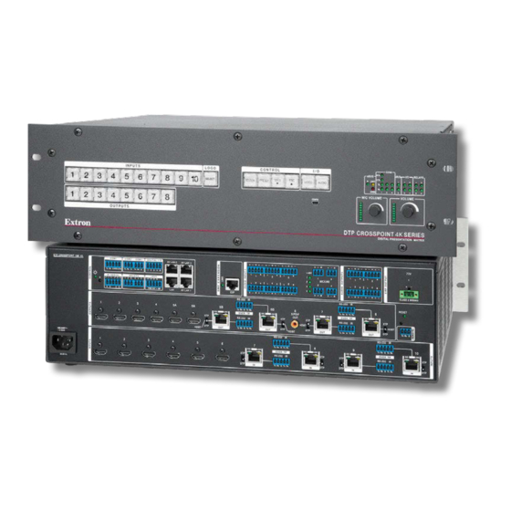
1 on the next page) distribute HDCP-compliant HDMI and Extron proprietary DTP or XTP video and audio signals. A matrix switcher routes any input sigal to any combination of outputs. It can route multiple input and output configurations simultaneously. - Page 10 Figure 1. Typical DTP CrossPoint 108 4K IPCP SA Application The switchers have RS-232 and infrared (IR) insertion ports on all DTP inputs and outputs that allow you to route bidirectional control signals to the connected devices. The switchers provide four mono microphone (mic)/line level inputs that can be mixed with one or all audio outputs.
-
Page 11: Dtp Input And Output Signals
The DTP CrossPoint can be operated by any of the following connected to the serial port, USB port, or a LAN port: • A control system • A PC and any of the following: • Programming Guide DSP SIS Commands... -
Page 12: Definitions
Paired outputs — Outputs that include two connectors: an HDMI connector and an LINK RJ-45 (TP) connector (such as output 5A and 5B on the DTP CrossPoint 108 4K). The paired signal outputs are duplicated between the HDMI (A) and TP (B) connectors. -
Page 13: Features
Features • All-in-one matrix switcher, scaler, and audio DSP — The DTP CrossPoint 4K Series delivers all of the core functionality of a conventional AV system in a single enclosure, making it ideal for presentation environments that require multiple displays. - Page 14 Embedded multi-channel bitstream formats are routed with the video to the HDMI and DTP outputs. • Output volume control — The DTP CrossPoint 4K Series provides master volume control for the line level and amplified (SA and MA models) audio outputs, as well as a separate control for mic volume. •...
- Page 15 Virtual buses allow inputs to be processed together as a group. The expansion matrix provides signal routing between the DTP CrossPoint 4K Series and a DMP 128 processor linked via the expansion port.
- Page 16 • Aspect ratio control — For inputs delivered to the scaled (HDMI and DTP) outputs, the aspect ratio of the video can be controlled by selecting a fill mode, which provides a full screen output, or a follow mode, which preserves the original aspect ratio of the input signal.
-
Page 17: Installation
50-60 Hz Tx Rx Tx Rx Tx Rx Tx Rx Figure 2. DTP CrossPoint 108 4K IPCP SA Matrix Switcher Rear Panel (Showing non-IPCP LAN Port, IPCP, and SA [Stereo Audio] Components) DTP CrossPoint 4K Series Matrix Switchers • Installation... -
Page 18: Video And Twisted Pair Input And Output Connections And Switches
13, on page 14, on page 15, on page 16, and page 16). • The DTP CrossPoint 82 is similar to the DTP CrossPoint 84, but with fewer connectors (see figure figure 7 on page 13, figure 9... - Page 19 The TP input consists of HDMI with embedded audio plus RS-232 and IR. • DTP position — Set this switch to the DTP position if the connected device is an Extron DTP transmitter. The TP input consists of HDMI with embedded audio, analog audio, and RS-232 and IR.
- Page 20 HDMI with embedded audio plus RS-232 and IR. • DTP position — Set this switch to the DTP position if the connected device is an Extron DTP receiver. The TP output consists of HDMI with embedded audio, analog audio, RS-232 and IR, and remote power.
-
Page 21: Audio Input And Output Connections
• Ensure the rated input voltage of the speakers matches the rated output voltage of the switcher. • Assurez-vous que la tension nominale d’entrée des enceintes soit compatible avec la tension nominale de sortie du sélecteur. • Use ‘Class 2 Wiring’ to connect speakers to the amplifier output. • Utilisez un câblage de classe 2 pour connecter les enceintes à la sortie de l’amplificateur. DTP CrossPoint 4K Series Matrix Switchers • Installation... -
Page 22: Serial And Ir Insertion Connections
Tx Rx Tx Rx cables). The following table identifies the Over TP outputs by matrix size. Matrix Outputs Matrix Outputs 10x8 5B, 6B, 7, 8 3B, 4B, 5, 6 3B, 4B 1B, 2B DTP CrossPoint 4K Series Matrix Switchers • Installation... -
Page 23: Control Connections
REMOTE port — Plug a serial RS-232 device into the matrix switcher via this 3.5 mm, REMOTE 3-pole captive screw connector for remote control of the switcher (see Serial and IR port connectors on page 21 to wire the connector). Tx Rx G DTP CrossPoint 4K Series Matrix Switchers • Installation... -
Page 24: Switcher Reset
Power Connector, 8x4 Matrix Power connector — Plug a standard IEC power cord into this connector to connect the switcher to a 100 VAC to 240 VAC, 50-60 Hz power source. 50-60 Hz DTP CrossPoint 4K Series Matrix Switchers • Installation... -
Page 25: Detailed Pin Assignments, Wiring, And Sample Applications
T568B at the other (Tx and Rx pairs called a "straight-through" cable, because Connector reversed) is a "crossover" cable. no pin/pair assignments are swapped. Figure 17. RJ-45 Connector and Pinout Tables DTP CrossPoint 4K Series Matrix Switchers • Installation... - Page 26 TP and Expansion ports The TP input and output ports are compatible with Extron XTP DTP 24 SF/UTP cables, as well as CAT 5e, 6, 6a, and 7 shielded twisted pair (F/UTP, SF/UTP, and S/FTP) cable. The Expansion port requires CAT 5e, 6, 6a, or 7 shielded twisted pair cable.
- Page 27 101-005-02 XTP DTP 24 Plug • If you are not using XTP DTP 24 cable, Extron recommends, at a minimum, using 24 AWG, solid conductor, STP cable with a minimum bandwidth of 400 MHz. • Terminate cables with shielded connectors to the TIA/EIA-T568B standard as straight-through (patch) cables...
- Page 28 Configurator, the Output Signal Source is set to From DSP (see controls on page 108). You can make audio breakaway ties with an SIS command (see page 63) or the Product Configuration Software (see Matrix Software on page 77). DTP CrossPoint 4K Series Matrix Switchers • Installation...
-
Page 29: Front Panel Configuration Port
Remote port, but it is easier to access than the rear port after the matrix switcher has been installed and cabled. NOTE: A front panel Configuration port connection and a rear panel Remote port connection can both be active at the same time. If commands are sent simultaneously to both, the command that reaches the processor first is handled first. DTP CrossPoint 4K Series Matrix Switchers • Installation... -
Page 30: Operation
Operation This section describes the front panel operation of the DTP CrossPoint 4K Series, including: • Front Panel Controls and Indicators • Front Panel Operations • Rear Panel Operations • Ethernet to RS-232 Insertion • Troubleshooting • Configuration Worksheets Front Panel Controls and Indicators... -
Page 31: Input And Output Buttons
DTP CROSSPOINT 4K SERIES DIGITAL PRESENTATION SWITCHER D E F G H I Figure 25. Front Panel, DTP CrossPoint 4K Series (IPCP Model) Input buttons (see page 27) ESC button (see page 31) Output buttons (see page 29) VIDEO button (see page 32) - Page 32 • (Selected inputs, based on matrix size) Select and display the control insert configuration for input. • (Input 1 and Input 2 only) Toggle background illumination of the buttons on and off. DTP CrossPoint 4K Series Matrix Switchers • Operation...
- Page 33 NOTE: See Front Panel Operations, beginning on page 34, for detailed descriptions of the following operations. Input and Output button secondary functions (continued) 10x8 matrix 8x6 matrix 8x4 matrix 8x2 matrix Control insert Action 1 Input 4 and configuration Output 4 blink: Select config. mode.
-
Page 34: Logo Select Button
Logo mode, in which you can apply a logo to one or more of outputs 5 through 8 (scaled outputs). NOTES: • The switcher has memory space for 16 bitmapped logos (PNG, BMP, and TIF format). • Logos are created and saved using the Product Configuration Software (see the PCS Help file). DTP CrossPoint 4K Series Matrix Switchers • Operation... -
Page 35: Control Buttons
Selects 19200 baud for the rear panel Remote port in Serial Port Configuration mode and indicates the selection. • With the VIEW and ESC buttons, selects front panel security Lock mode 2 or toggles between mode 0 (unlocked) and mode 2. DTP CrossPoint 4K Series Matrix Switchers • Operation... - Page 36 With the PRESET button and VIEW button, selects between front panel locks (Lock mode 2 and Lock mode 0). • With the VIEW button, selects between front panel locks (Lock mode 2 and Lock mode 1). DTP CrossPoint 4K Series Matrix Switchers • Operation...
-
Page 37: I/O Buttons
The sensitivity of the encoder (the amount [dB] of volume adjustment per step of rotation) varies depending on the current volume setting (see the last column in the table). DTP CrossPoint 4K Series Matrix Switchers • Operation... -
Page 38: Control Processor Indications
171, for details on using the labeling software, blank labels you can fill in yourself, and the procedure for removing and replacing the translucent covers. INPUTS 9 10 Computer 6 7 8 Document Camera OUTPUTS Figure 26. Sample Button Icons DTP CrossPoint 4K Series Matrix Switchers • Operation... -
Page 39: Front Panel Operations
NOTE: The switcher is shipped from the factory in Lock mode 2. See Setting the Front Panel Locks (Executive Modes) on page 45 for a detailed list of basic and advanced functions and the procedure to set the various front panel locks. DTP CrossPoint 4K Series Matrix Switchers • Operation... -
Page 40: Making Ties
• As each input and output is selected, the associated output button blinks the appropriate color to indicate a tentative tie. Buttons for outputs that were already tied to the input light the appropriate color steadily. Outputs that are already tied can be left on, along with new blinking selections, or toggled off by pressing the associated output button. DTP CrossPoint 4K Series Matrix Switchers • Operation... - Page 41 The current configuration (see figure 27) is now input 5 video and audio tied to output 1, output 3, and output 4. Input Video Output Audio Figure 27. Final Configuration, Example 1 DTP CrossPoint 4K Series Matrix Switchers • Operation...
- Page 42 Video — Input 5 video is tied to output 1, output 2, output 3, and output 4. • Audio — Input 5 audio is tied to output 1, output 3, and output 4. Input Video Output Audio Figure 28. Final Configuration, Example 2 DTP CrossPoint 4K Series Matrix Switchers • Operation...
- Page 43 Video — Input 5 video is tied to output 1, output 2, output 3, and output 4. • Audio — Input 5 audio is tied to output 1 and output 3. Input Video Output Audio Figure 29. Final Configuration, Example 3 DTP CrossPoint 4K Series Matrix Switchers • Operation...
-
Page 44: Viewing The Configuration
Amber if no inputs are tied (not shown in this example) Green if no video inputs are tied (only audio is tied) Red if no audio inputs are tied (only video is tied). OUTPUTS DTP CrossPoint 4K Series Matrix Switchers • Operation... - Page 45 7. Exit View-only mode: Press and release the VIEW button. Press the button. All input buttons and output buttons VIEW return to unlit or background illumination. The View button returns to unlit or background illumination. DTP CrossPoint 4K Series Matrix Switchers • Operation...
-
Page 46: Recalling Presets
Preset Preset Preset Preset Preset Preset Preset Preset Preset Preset INPUTS Input 8x4 and buttons 8x2 Matrix Sizes Output buttons OUTPUTS Preset Preset Preset Preset Figure 30. DTP CrossPoint 4K Preset Locations DTP CrossPoint 4K Series Matrix Switchers • Operation... -
Page 47: Assigning And Unassigning Logos
Matrix Outputs Matrix Outputs 10x8 5, 6, 7, 8 3, 4, 5, 6 3, 4 1, 2 NOTES: • The switcher has memory space for 16 bitmapped logos. • Logos are created and saved using the Product Configuration Software (see the PCS Help File). DTP CrossPoint 4K Series Matrix Switchers • Operation... - Page 48 5. Confirm the change: Press and release the ENTER button. Press the Enter button to confirm the change. All input buttons and output buttons ENTER return to unlit or background illumination. The Enter button returns to unlit or background illumination. DTP CrossPoint 4K Series Matrix Switchers • Operation...
- Page 49 4. Confirm the change: Press and release the ENTER button. Press the Enter button to confirm the change. All input buttons and output buttons ENTER return to unlit or background illumination. The Enter button returns to unlit or background illumination. DTP CrossPoint 4K Series Matrix Switchers • Operation...
-
Page 50: Configuring The Input Audio
All input buttons and output buttons ENTER return to unlit or background illumination. The Enter button returns to unlit or background illumination. 6. Repeat steps 2 through 5 as necessary for other inputs. DTP CrossPoint 4K Series Matrix Switchers • Operation... -
Page 51: Configuring The Tp Insertion Ports
5. Confirm the change: Press and release the ENTER button. Press the Enter button to confirm the change. All input buttons and output buttons ENTER return to unlit or background illumination. The Enter button returns to unlit or background illumination. DTP CrossPoint 4K Series Matrix Switchers • Operation... -
Page 52: Selecting The Remote Port Baud Rate
Input 2 buttons simultaneously for approximately 2 seconds (see figure 31). Press and hold the buttons. After the illumination status of the buttons changes (after approximately 2 seconds), release the buttons. Figure 31. Toggling Background Illumination On or Off DTP CrossPoint 4K Series Matrix Switchers • Operation... -
Page 53: Setting The Front Panel Locks (Executive Modes)
Lock mode 0 CONTROL CONTROL ENTER PRESET VIEW VIDEO AUDIO ENTER PRESET VIEW VIDEO AUDIO Press and hold for 2 seconds. Figure 32. Toggling Front Panel Lock Between Mode 2 and Mode 0 DTP CrossPoint 4K Series Matrix Switchers • Operation... -
Page 54: Performing A System Reset From The Front Panel
NOTES: • System reset does not reset the Internet protocol (IP) settings or replace user-installed firmware. • This function resets only the switcher, not the IPCP control processor or any connected DTP endpoints. • The factory configured passwords for all accounts on this device have been set to the device serial number. In the event of a complete system reset, the passwords convert to the default, which is no... -
Page 55: Rear Panel Operations
LED blinks four times in quick succession. RESET of a complete system reset, the passwords convert to the default, which is no password (see Password SIS commands page 74 to change the password). DTP CrossPoint 4K Series Matrix Switchers • Operation... -
Page 56: Performing A Boot Code Reset
Reset all input and output buttons return to either unlit or to background illumination and the Video and Audio buttons turn on. Release the button. Reset RESET Figure 35. Factory FIrmware Reset DTP CrossPoint 4K Series Matrix Switchers • Operation... -
Page 57: Performing Network Settings And Full Factory Resets
You must physically connect a cable connected to the captive screw connector where a control signal is to be inserted. The insert inputs and outputs, whether inserted via Ethernet or captive screw connectors, can support up to a 115k baud rate. DTP CrossPoint 4K Series Matrix Switchers • Operation... -
Page 58: Enabling Ethernet And Captive Screw Insertion
POWER AUDIO RS-232 0.7A MAX Tx Rx Tx Rx Tx Rx DTP OUT DTP HDMI 4K 230 Tx RS-232 HD Camera Figure 37. Typical Ethernet to RS-232 Insertion to an Input Endpoint DTP CrossPoint 4K Series Matrix Switchers • Operation... - Page 59 Configuring RS-232 Insertion Parameters, steps 1, 4, and 5). Alternatively, you can change the port RS-232 settings via SIS commands (see the Ethernet insertion serial port insert parameters SIS commands on page 73). DTP CrossPoint 4K Series Matrix Switchers • Operation...
-
Page 60: Captive Screw Signal Insertion
5. Check the cabling and make corrections as necessary. 6. Call the Extron Sales and Technical Support Hotline if necessary. See www.extron.com for the phone number in your region of the world. DTP CrossPoint 4K Series Matrix Switchers • Operation... -
Page 61: Configuration Worksheets
Worksheet Example 1: System Equipment Figure 39 shows a portion of a worksheet for a DTP CrossPoint 108 4K switcher in a fictional organization with the system hardware annotated. Inputs 6, 8, 9, and 10 have no connection in this organization, so they are crossed out on the worksheet. -
Page 62: Worksheet Example 2: Daily Configuration
Her microphone audio (input 1) is played in the classrooms (output 1, 5A, and 5B). • Audio from another PC (input 3) is output to a local device via a DTP receiver (output 4). Worksheet Example 3: Test Configuration Fine tuning the system requires a test configuration (see figure 41). A test pattern from an Extron VTG 400 (input 5) goes to all monitors (outputs 1, 3, 4, 5A, 5B, 6A, and 6B). -
Page 63: Worksheets
Title: Video: Audio: Fill in the preset number and use colors, dashes, and the like to make connecting lines. Indicate if the configuration is for video, audio, or both. indicates paired outputs DTP CrossPoint 4K Series Matrix Switchers • Operation... - Page 64 Title: Video: Audio: Fill in the preset number and use colors, dashes, and the like to make connecting lines. Indicate if the configuration is for video, audio, or both. indicates paired outputs DTP CrossPoint 4K Series Matrix Switchers • Operation...
- Page 65 Title: Video: Audio: Fill in the preset number and use colors, dashes, and the like to make connecting lines. Indicate if the configuration is for video, audio, or both. indicates paired outputs DTP CrossPoint 4K Series Matrix Switchers • Operation...
- Page 66 Title: Video: Audio: Fill in the preset number and use colors, dashes, and the like to make connecting lines. Indicate if the configuration is for video, audio, or both. indicates paired outputs DTP CrossPoint 4K Series Matrix Switchers • Operation...
-
Page 67: Programming Guide
The front panel Configuration port (see on page 21) is a standard USB port. A USB cable, terminated on one end with a USB mini-B male connector, is available at any local electronics store. DTP CrossPoint 4K Series Matrix Switchers • Programming Guide... -
Page 68: Ethernet (Lan) Ports
Default IP addresses To access the DTP CrossPoint switcher via the LAN port, you need the IP address for the unit, and may need the subnet mask and the gateway address. If the IP address has been changed to an address comprised of words and characters, you can determine the actual numeric IP address for the DTP CrossPoint using the ping (ICMP) utility. -
Page 69: Host-To-Switcher Instructions
Using verbose mode Telnet connections to a DTP CrossPoint switcher can be used to monitor for changes that occur on the switcher, such as front panel operations and SIS commands from other Telnet sockets or a serial port. For a Telnet session... -
Page 70: Switcher Error Responses
• response examples are shown throughout the table. The SIS commands are not case sensitive. The ASCII to HEX conversion table below is for use with the command and response table. DTP CrossPoint 4K Series Matrix Switchers • Programming Guide... -
Page 71: Command And Response Table For General Matrix Switcher Commands
00 – the highest numbered input for your model (00 = untied input, valid for tie commands only) = Output number 00 – the highest numbered output for your model (00 = untied output, valid for tie commands only) DTP CrossPoint 4K Series Matrix Switchers • Programming Guide... - Page 72 1 = Enable (mute) 2 = Mute video and sync enable and disable = Input audio source 0 = Auto (default) 2 = Analog 2-channel audio 1 = HDMI (digital audio) DTP CrossPoint 4K Series Matrix Switchers • Programming Guide...
- Page 73 1 = On (always encrypt HDMI outputs) 2 = Follow input with continuous DVI trials 3 = Always encrypt HDMI outputs with continuous DVI trials = HDCP notification 0 = Black screen 1 = Green screen (default) DTP CrossPoint 4K Series Matrix Switchers • Programming Guide...
- Page 74 7 = HDMI YUV Limited (RGB 422, 016 - 255 audio, InfoFrames) = Output video bit depth 0 = Auto (default) 1 = 8-bit = Video mute status 0 = No mutes 2 = Video and sync 1 = Video mute DTP CrossPoint 4K Series Matrix Switchers • Programming Guide...
- Page 75 NOTE: The HTML language reserves certain characters for specific functions (see Special Characters). = Scaler preset 001 – 128 = Logo number 00 – 16 (00 = no logo) X2& = Preset number 01 – 32 DTP CrossPoint 4K Series Matrix Switchers • Programming Guide...
- Page 76 192 . 168 . 254 .2 54 and subnet mask to 255 . 255 . 000 . 000 . NOTE: The absolute reset ( ) command resets only the switcher, not any connected DTP endpoints. ZQQQ Absolute reset, excluding IP settings...
- Page 77 00 – the highest numbered input for your model (00 = untied input, valid for tie commands only) 000 through 127 (064 = default) = Picture adjustments = Position ±10240 Horizontal position specified from left, Vertical position specified from top DTP CrossPoint 4K Series Matrix Switchers • Programming Guide...
- Page 78 = Active pixels and active lines Dependent on the input signal and selected scaling. X3& = Aspect ratio fill or follow 2 = follow 1= fill (default) = Overscan percentage 0 = 0% (default) 1 = 2.5% 2 = 5.0% DTP CrossPoint 4K Series Matrix Switchers • Programming Guide...
- Page 79 1 = No active input, timer is running, output sync is still active 2 = No active input, timer is expired, output sync is disabled = Scaler output resolution and rate See the table on page 72. DTP CrossPoint 4K Series Matrix Switchers • Programming Guide...
- Page 80 00 – the highest numbered input for your model (00 = untied input, valid for tie commands only) = HDCP authorized device, freeze, and film 1 = On or enable 0 = Off or disable = Logo number 00 – 16 (00 = no logo) DTP CrossPoint 4K Series Matrix Switchers • Programming Guide...
- Page 81 = Captive screw or UART 0 = Captive screw RS-232 insert (default) 1 = Ethernet RS-232 insert (UART) = Port number 02 — 0n = UARTs 2 — n (DTP input and output ports) 10x8 matrix 02 = Input 7...
-
Page 82: Port Specific And Communications Protocol Sis Commands
Hardware, Software, None (only the first letter required) (N = default) = Flow control (first letter only) = Data pacing between bytes 0000 – 1000 (in milliseconds, default = 0 ms). (For a host port, this value is ignored and returns 0.) DTP CrossPoint 4K Series Matrix Switchers • Programming Guide... - Page 83 , returns Ipn• X7& = Port timeout interval (in 10-second increments) 1 (= 10 seconds) - 65000 (default is 30 = 300 seconds = 5 minutes) = Ethernet port number 0 = off, custom port numbers must be 1024 or higher DTP CrossPoint 4K Series Matrix Switchers • Programming Guide...
-
Page 84: Ipcp Pro Control Processor Information
1 = Enabled (default) IPCP Pro Control Processor Information The DTP CrossPoint 4K IPCP models include a built-in high-performance IPCP Pro control processor with multiple AV LAN ports that supports the LAN ports and other functionality. See the IPCP Pro Series User Guide available at www.extron.com. -
Page 85: Matrix Software
Matrix Software The DTP CrossPoint Matrix Switcher can be remotely controlled, monitored, or configured via: • SIS commands (see Programming Guide on page 59) • HTML Pages Built-in HTML pages (see on page 146) • The following two Extron computer programs: •... -
Page 86: Software Operational Considerations And Installation
2 2 2 2 2 2 2 2 2 2 2 2 2 2 2 2 3 3 3 3 3 3 3 3 Figure 42. Downloading a Software or Firmware Package (PCS Shown) DTP CrossPoint 4K Series Matrix Switchers • Matrix Software... - Page 87 3 3 3 3 5 5 5 5 5 5 5 5 4 4 4 4 4 4 4 4 2 2 2 2 2 2 2 2 Figure 44. Log in Dialog Box DTP CrossPoint 4K Series Matrix Switchers • Matrix Software...
- Page 88 Uninstall Extron Product Configuration Software DSP Configurator — • Folder — C:\Program Files\Extron\DSP_Configurator • Group folder — Extron Electronics\DSP Configurator • DSP Configurator Help • DSP Configurator • Uninstall DSP Configurator DTP CrossPoint 4K Series Matrix Switchers • Matrix Software...
-
Page 89: Product Configuration Software
(see on page 83). For all other PCS operations, see the PCS Help file for the DTP CrossPoint Matrix Switchers. Figure 47. Product Configuration Software (DTP CossPoint 108 4K IPCP SA Shown) DTP CrossPoint 4K Series Matrix Switchers • Matrix Software... -
Page 90: Device Menu
Updating the Firmware on page 86). • <Device name> Help — Opens the device help file. • About This Module... — Shows the version of the unit-specific part of the software. DTP CrossPoint 4K Series Matrix Switchers • Matrix Software... -
Page 91: Assigning And Unassigning Logos
3 3 3 3 3 3 3 3 3 3 3 3 Figure 48. Scaler Settings Panel, DTP CrossPoint 108 4K Shown 2. If necessary, click the Logos tab to open the logos controls (see figure 48, 3. Click the desired logo in the Logo Management column ( 4. -
Page 92: Configuring Rs-232 Insertion Parameters
2 2 2 2 3 3 3 3 3 3 3 3 3 3 3 3 3 3 3 3 3 3 Figure 49. General Settings Panel, DTP CrossPoint 108 4K Shown DTP CrossPoint 4K Series Matrix Switchers • Matrix Software... - Page 93 6. If you want to change the change the port number starting point, click in the Starting Point box (see figure on page 84) and type in a new value (see Port number on page 55 to understand how this affects insertion port numbering). DTP CrossPoint 4K Series Matrix Switchers • Matrix Software...
-
Page 94: Updating The Firmware
15) or front panel Configuration port (see on page 21). 6. Start the Product Configuration Software and connect to the unit (see Starting the Program on page 81). DTP CrossPoint 4K Series Matrix Switchers • Matrix Software... - Page 95 7. On the DTP CrossPoint tab, click > Update firmware > Update Firmware this Device. The software asks you to confirm that you want to continue the update (see figure 52 on the next page). DTP CrossPoint 4K Series Matrix Switchers • Matrix Software...
- Page 96 13. Click Close. The Product Configuration Software window returns to the front. 14. Click the in the connection tab to completely disconnect the program from the unit and then reconnect the Starting the Program program as described in on page 81. DTP CrossPoint 4K Series Matrix Switchers • Matrix Software...
-
Page 97: Dsp Configurator Program
2. Select the DTP CrossPoint switcher in the drop-down list (see figure 53, 3. Click OK ( TIP: If you have only DTP CrossPoint switchers of the same model, click Always perform the selected action to eliminate step 2 in future startups. figure 54 The DSP Configurator program starts in Emulate mode (see on the next page). - Page 98 * This output 1 amplifier block (in ) is not present on non-IPCP models. Figure 54. DSP Configurator (SA) Program Window, DTP CrossPoint 108 Shown DTP CrossPoint 4K Series Matrix Switchers • Matrix Software...
-
Page 99: Using The Program
Mic-to-virtual-send-bus mixer block (see Mic-to-virtual-send-bus mixer block on page 110) Virtual returns-to-virtual-send-bus mixer block (see Virtual returns-to-virtual-send-bus mixer block page 110) Expansion inputs-to-virtual-send-bus mixer block Expansion inputs-to-virtual-send-bus mixer block (see on page 110) DTP CrossPoint 4K Series Matrix Switchers • Matrix Software... - Page 100 Click to select window. in this block. the desired process. Figure 56. Selecting and Inserting a Typical Processor Block Dialog Box DTP CrossPoint 4K Series Matrix Switchers • Matrix Software...
- Page 101 124 and the specific tabs for the processor types). When a processor is bypassed, a red indicator in the block turns on. The block can be removed from the audio stream by selecting it and depressing the keyboard <Delete> key or by right-clicking and selecting Delete. DTP CrossPoint 4K Series Matrix Switchers • Matrix Software...
- Page 102 Auto. • Embedded LPCM input audio passes directly to an HDMI or DTP output, bypassing the DSP, if the Output Signal Source control in the Volume block of that output is set to Original (see Output signal processor chain Volume controls on page 109).
- Page 103 94). Gain, mute controls, and meters are disabled and unavailable for operation throughout the DSP. • Multi-channel input audio passes to an HDMI or DTP output, bypassing the DSP, if the Output Signal Source control in the Volume block of that output is set to Original (see Output signal processor chain Volume controls on page 109).
- Page 104 Notch filter — These filters attenuate a narrow band of frequencies to minimize feedback. DTP CrossPoint 4K Series Matrix Switchers • Matrix Software...
- Page 105 2 2 2 2 2 2 2 2 2 2 2 2 2 2 2 2 2 2 3 3 3 3 3 3 3 3 3 3 3 3 3 3 3 3 3 3 DTP CrossPoint 4K Series Matrix Switchers • Matrix Software...
- Page 106 NOTE: Condenser mics require phantom power. Dynamic mics do not require power. Do not enable phantom power when using dynamic mics. Audio popping can occur when a dynamic mic is plugged in and phantom power is on. DTP CrossPoint 4K Series Matrix Switchers • Matrix Software...
- Page 107 Open/collapse functions icon ( ) — Click to access the advanced AEC settings. NOTE: Most users do not need to change the advanced settings. See Advanced AEC Controls page 136 for descriptions of these settings. DTP CrossPoint 4K Series Matrix Switchers • Matrix Software...
- Page 108 The current source is not available as a target (a source cannot duck itself). If the current source has been designated as a target of another input channel, that input channel is not available (a target cannot be the source). DTP CrossPoint 4K Series Matrix Switchers • Matrix Software...
- Page 109 £ £ £ £ Show AM Group Details — Opens a dialog box that details current groups and the parameter member assignments to each (see Automix Group ¢ Details on page 138 for particulars). DTP CrossPoint 4K Series Matrix Switchers • Matrix Software...
- Page 110 112 to create group masters). • Multiple masters can be created for a fader, in which case the indicator is • By default, the front panel Mic Volume knob controls this fader. DTP CrossPoint 4K Series Matrix Switchers • Matrix Software...
- Page 111 Gain control (pre-mixer) — The always-present gain control provides a fader with a gain range of 12 dB to -100 dB, adjustable in 0.1 dB increments. The Gain block is identical to as described for the Mic/line inputs signals Gain block on page 94. DTP CrossPoint 4K Series Matrix Switchers • Matrix Software...
- Page 112 112 to create group masters). • Multiple masters can be created for a fader, in which case the indicator is • By default, the front panel Volume knob controls this fader. DTP CrossPoint 4K Series Matrix Switchers • Matrix Software...
- Page 113 Virtual Returns Expansion Inputs Figure 58. Switcher-to-output Mixer Block and Mix-point Dialog Box, DTP CrossPoint 108 4K Shown To mute or unmute an input, double-click one of the mix-points ( ) to open a mix-point dialog box. Click the Mute button ( ) in the dialog box to unmute or mute the applicable input.
- Page 114 (column) of mix-points, audio is redirected up. In the second column, audio is redirected down. • The virtual send bus does not exit the DSP, but is looped around for potential additional processing. DTP CrossPoint 4K Series Matrix Switchers • Matrix Software...
- Page 115 4 4 4 4 2 2 2 2 2 2 2 2 2 2 2 2 2 2 2 2 2 2 Figure 60. Output Mixer Blocks and Mix-points, DTP CrossPoint 108 4K Shown DTP CrossPoint 4K Series Matrix Switchers • Matrix Software...
- Page 116 2 2 2 2 2 2 2 2 2 2 2 2 2 2 2 2 2 2 3 3 3 3 3 3 3 3 3 3 3 3 3 3 3 3 3 3 DTP CrossPoint 4K Series Matrix Switchers • Matrix Software...
- Page 117 HDMI (HDMI) — Output 1 through 4 (all matrix sizes, except 8x2, in which both HDMI outputs are paired with DTP) • DTP (DTP) (paired outputs include HDMI) — Output 1 and 2 (8x2 matrix size) Output 3 and 4 (8x4 matrix size) Output 3 through 6 (8x6 matrix size)
-
Page 118: Click And Drag The Desired Fader
If the Output Signal Source is set to Original, the digital audio embedded in the digital (HDMI or DTP) signal continues to be routed as part of the digital signal and is output with the video, even for audio breakaway ties. - Page 119 1 1 1 1 2 2 2 2 2 2 2 2 2 2 2 2 2 2 2 2 2 2 Figure 62. Virtual Send Bus and Expansion Bus Mixer Blocks and Mix-points DTP CrossPoint 4K Series Matrix Switchers • Matrix Software...
- Page 120 Front row audience members need less mic audio mixed in, and you want to insert varying degrees of delay for different audience rows. The output 1 through output 3 analog volume controls can be grouped into a master that controls the volume throughout the room (see figure 64). DTP CrossPoint 4K Series Matrix Switchers • Matrix Software...
- Page 121 3. In the Select Control Type field, click the + to expand the Gain or Mute tree and then select a control to assign it to the group ( DTP CrossPoint 4K Series Matrix Switchers • Matrix Software...
-
Page 122: Figure 60 On The Previous Page
Soft limits can be defined using the mouse by clicking and dragging the Soft Limit icon. The resolution is 0.1 dB. For more precise setting, using the keyboard (see Setting group master soft limits page 129). DTP CrossPoint 4K Series Matrix Switchers • Matrix Software... - Page 123 • You must select a group before the other controls in the dialog box are active. • The size of the increment can be changed from its default value of 1 dB by typing a value in the Increment Value or Decrement Value field, to as fine as 0.1 dB. DTP CrossPoint 4K Series Matrix Switchers • Matrix Software...
- Page 124 I/O, or pressing the keyboard <F4> key. Switching operations using the AV matrix block (see AV matrix block page 103) tie only video (video breakaway). Figure 69. DSP Configurator Program Window, Video-only I/O Page DTP CrossPoint 4K Series Matrix Switchers • Matrix Software...
-
Page 125: Presets
103) tie only audio. Presets The DTP CrossPoint 4K Series can store up to 32 presets and can include both selected ties and selected audio signal processing settings made in the program. Presets that do not include a full configuration of ties and settings, when recalled, overwrite only a portion of the current configuration, leaving other ties and settings unchanged, and are useful when only selected ties, settings, or both;... - Page 126 2. Click Recall to load and make active the selected preset ( TIPS: • Click Cancel to discard the preset recall (but not deleting the preset) and return to the current configuration. • Click Delete to permanently erase the preset. DTP CrossPoint 4K Series Matrix Switchers • Matrix Software...
-
Page 127: Emulate Mode Vs. Live Mode
) (for LAN port connection [preferred] — Proceed to step 3 on the next page. • USB tab ( step ) (for front panel Configuration port connection — Proceed to NOTE: Do not select the RS-232 tab. Configuration is too complex for this port. DTP CrossPoint 4K Series Matrix Switchers • Matrix Software... - Page 128 Proceed to step 5. 4. If you selected USB in step 2: a. Click the USB Devices drop-down list and select the switcher ( b. Click OK ( DTP CrossPoint 4K Series Matrix Switchers • Matrix Software...
- Page 129 ¢ ¢ ¢ ¢ ¢ ¢ ¢ ¢ ¢ ¢ ¢ ¢ £ £ £ £ £ £ £ £ £ £ £ £ £ £ £ £ £ £ Figure 72. Selecting Live Mode, Continued DTP CrossPoint 4K Series Matrix Switchers • Matrix Software...
- Page 130 If a password was required and not entered or if an incorrect password was entered, the program prompts for the password. NOTE: The factory configured passwords for all accounts on this device have been set to the device serial number. In the event of a complete system reset, the passwords convert to the default, which is no password. DTP CrossPoint 4K Series Matrix Switchers • Matrix Software...
-
Page 131: Dsp Configurator Windows Menus
Audio & Video I/O — Selects the audio and video I/O page for the DSP Configurator program (the default view). Audio I/O — Selects the audio-only I/O page for the DSP Configurator program. Video I/O — Selects the video-only I/O page for the DSP Configurator program. DTP CrossPoint 4K Series Matrix Switchers • Matrix Software... - Page 132 Device Setting — Opens a dialog box that provides a means to set the IP address and passwords of the unit and to set the baud rate for the serial port. DTP CrossPoint 4K Series Matrix Switchers • Matrix Software...
- Page 133 DSP Configurator. The ties and settings of the preset are not in sync between the DSP Configurator program and the switcher. DSP Configurator Mode buttons Allows you to select between Live mode and Emulate mode (see Emulate mode vs. Live mode on page 119, for more information). DTP CrossPoint 4K Series Matrix Switchers • Matrix Software...
-
Page 134: Keyboard Navigation
) sequential jumps are in the following order: • AV matrix block ( • Output processor chains and mixers ( • <Shift + Tab> key combination — Reverses the direction of the Tab key function. DTP CrossPoint 4K Series Matrix Switchers • Matrix Software... -
Page 135: Output
8. If desired to make ties from a different input, press left arrow once, and repeat steps 1 through 7. 9. Press <Tab> , <Esc> , right arrow , or left arrow to exit the set ties operation. DTP CrossPoint 4K Series Matrix Switchers • Matrix Software... - Page 136 ) and enter a preset name. NOTE: Unless you enter a specific number, name, or both, DSP Configurator enters the next sequential unused preset number and the name Preset number c. Press <Tab> to highlight the OK button ( ) and press <Enter> ( DTP CrossPoint 4K Series Matrix Switchers • Matrix Software...
- Page 137 <Ctrl>-<Page Up> or <Ctrl>-<Page Down> — Moves the soft lower limit in 10 dB increments. • <Ctrl>-<Home> — Moves the soft lower limit to the fader position. • <Ctrl>-<End> — Moves the soft lower limit to the lower default. DTP CrossPoint 4K Series Matrix Switchers • Matrix Software...
-
Page 138: Signal Path Building Blocks
The building blocks can be renamed and processor blocks further customized according to the requirements of the system. * This output 1 amplifier block is not present on non-IPCP models. Figure 76. Building Blocks Availability DTP CrossPoint 4K Series Matrix Switchers • Matrix Software... - Page 139 The input device name and the processor chain change to shows the adjustments. 1 1 1 1 1 1 1 1 1 1 1 1 1 1 1 1 1 1 DTP CrossPoint 4K Series Matrix Switchers • Matrix Software...
- Page 140 1 1 1 1 1 1 1 1 1 1 1 1 1 1 1 1 1 1 2 2 2 2 2 2 2 2 2 2 2 2 2 2 2 2 2 2 DTP CrossPoint 4K Series Matrix Switchers • Matrix Software...
- Page 141 This utility lets you organize listed building blocks. You can also import and export the building blocks file so that you can use your set of building blocks on other computers. DTP CrossPoint 4K Series Matrix Switchers • Matrix Software...
- Page 142 2. Browse to the location where the file is to be saved. 3. In the File Name field, leave the current file name or enter a new file name. 4. Click Save. DTP CrossPoint 4K Series Matrix Switchers • Matrix Software...
-
Page 143: Aec Tutorial
AEC Tutorial The DTP CrossPoint 4K Series provide an acoustic echo cancellation processor for each of the four mic/line inputs. A single reference can be selected for each AEC from a list of the other three mic/line inputs or the virtual returns. -
Page 144: Advanced Aec Controls
1. Insert a ducking processor to mic #1. 2. Open the ducker configuration box and select the desired duck targets (see figure 78 on the next page). In this example, post-matrix 1 through 4 are the ducking targets. DTP CrossPoint 4K Series Matrix Switchers • Matrix Software... - Page 145 Since mic 2 is a target of mic 1, if a signal on mic 1 exceeds the ducking threshold, mics 2 through 4 are still ducked regardless of whether the signal on mic 2 exceeds its ducking threshold. NOTE: No input will be ducked more than the amount set in the applicable by (dB): field. DTP CrossPoint 4K Series Matrix Switchers • Matrix Software...
-
Page 146: Automix Tutorial
An automixer manages multiple microphone sources, gating or varying input gain automatically. When properly set, the automixer system improves use and performance when multiple mics are in use. The two basic types of automixer that the DTP CrossPoint 4K uses lets the user choose between are gated and gain-sharing. •... - Page 147 Last mic mode can minimize the frequency of gate changes. This prevents rapid switching of input mics by, ensuring that a talker is not gated off when their speech is paused. After the automixer is configured, ensure that you set the appropriate mix-points to include automixing. DTP CrossPoint 4K Series Matrix Switchers • Matrix Software...
-
Page 148: Expansion Port Operation Within The Dsp
LED, in the Installation section on page 14) allows a DTP CrossPoint matrix switcher and an Extron DMP 128 ProDSP Digital Matrix Processor to be connected together for bidirectional communications with 16 channels of input and output audio. Audio that is processed in one unit can be directly input to the other unit to harness its processing capabilities. - Page 149 Expansion input channels The DTP CrossPoint accepts 16 expansion input channels (see figure 82). Expansion inputs 9 through 16 are via Virtual Returns 9 through 16 in the DMP 128. DTP CrossPoint 108 DMP 128 ProDSP Digital Matrix Processor Figure 82.
-
Page 150: Optimizing The Audio
Meters within the DSP Configurator program are peak-type meters, referenced to “full scale,” or 0 dBFS. For the DTP CrossPoint 4K Series, 0 dBFS corresponds to 22 dBu, which is the maximum output level of the switcher. Setting the Input and Output Gain Structure Before calibrating loudness, set up the system gain structure. -
Page 151: Adjusting The Pre-Matrix Trim
You can reduce the chance of this inadvertent clipping by using the post-matrix trim control rather than the volume control (see Adjusting the Post-matrix Trim on the next page). DTP CrossPoint 4K Series Matrix Switchers • Matrix Software... -
Page 152: Setting The Mic Input And Mic Mix-Point Levels
However, Extron recommends using the output volume control of the matrix switcher for controlling output volume. If you are using loudness processing on the unit, it works only in conjunction with the output volume control. DTP CrossPoint 4K Series Matrix Switchers • Matrix Software... -
Page 153: Calibrating Loudness
DSP Configurator output volume to a relatively loud level. 9. Toggle the loudness bypass on and off to compare the difference between loudness off and on. At a loud listening level, this difference should be minimal, or barely perceivable. DTP CrossPoint 4K Series Matrix Switchers • Matrix Software... -
Page 154: Html Pages
HTML Pages The DTP CrossPoint 4K Series can be remotely controlled via: • SIS commands (see Programming Guide, beginning on page 63) • Matrix Software The Extron Product Configuration Software and DSP Configurator software (see page 85) • The built-in HMTL page (see below) This section details using the built-in HTML page to perform a variety of tasks. -
Page 155: Download The Startup Page
2 2 2 2 2 2 2 2 2 2 2 2 2 2 2 2 2 2 Figure 83. Privacy Notification 2. Click Proceed to <IP address> (unsafe) ( ) (or similar message). DTP CrossPoint 4K Series Matrix Switchers • HTML Pages... - Page 156 In the event of a complete system reset, the passwords revert to the default. • The default username is and the default password setting is no password. admin • Passwords are case sensitive. DTP CrossPoint 4K Series Matrix Switchers • HTML Pages...
- Page 157 1 1 1 1 1 1 1 1 1 1 1 1 1 1 1 1 1 1 1 1 1 1 1 1 1 1 1 1 Figure 85. Home Page DTP CrossPoint 4K Series Matrix Switchers • HTML Pages...
-
Page 158: Date & Time
Time Zone — Click the drop-down list to select the offset from Greenwich Mean Time (GMT). SAVE and CANCEL buttons — Click SAVE to take Date & Time changes or CANCEL to abandon them. Clicking either button closes the editable pane. DTP CrossPoint 4K Series Matrix Switchers • HTML Pages... - Page 159 — Click SAVE to take Date & Time changes or CANCEL to abandon them. SAVE and CANCEL buttons Clicking either button closes the editable pane. NOTE: The Sync to PC button (figure ) is not selectable on this screen. DTP CrossPoint 4K Series Matrix Switchers • HTML Pages...
-
Page 160: Network
5 5 5 5 5 5 5 5 5 5 5 5 5 5 5 5 5 5 5 5 5 5 DHCP On DHCP Off Figure 89. Editable Network Pane DTP CrossPoint 4K Series Matrix Switchers • HTML Pages... -
Page 161: Password
Password and Confirm Password — Click in these fields and type in valid password values to enter the appropriate values for your switcher. SAVE and CANCEL buttons — Click SAVE ( ) to take Password changes or CANCEL to abandon them. Clicking either button closes the editable pane. DTP CrossPoint 4K Series Matrix Switchers • HTML Pages... -
Page 162: Firmware
1. Download the firmware (see Installing the Software, steps 1 through 6 on page 78). 2. Click SELECT FILE (see figure 92, ). An Open dialog box opens (see figure 93 on the next page). DTP CrossPoint 4K Series Matrix Switchers • HTML Pages... - Page 163 Login dialog box (see figure 84 on page 148). To continue to remotely operate the switcher, you Download the Startup Page, step 4 on page 147). must reconnect (see DTP CrossPoint 4K Series Matrix Switchers • HTML Pages...
- Page 164 The RS-232 selection on the page (see figure 85 on page 149) opens a read-only pane that shows the Home status of the switcher rear panel REMOTE port (see figure 96). Figure 96. RS-232 Selection DTP CrossPoint 4K Series Matrix Switchers • HTML Pages...
-
Page 165: Dsp Sis Comands
= Group fader soft limit dB value, in 0.1 dB increments. must be within the range for the gain block grouped in X8& = Group type 6= gain 12 = mute DTP CrossPoint 4K Series Matrix Switchers • Matrix Software... - Page 166 Input Input Gain Pre-mixer Input Input Gain Pre-mixer Gain Gain Input 1 Input 3 40000 40100 40002 40102 Input 2 Input 4 40001 40101 40003 40103 table. Object ID Values DTP CrossPoint 4K Series Matrix Switchers • DSP SIS Commands...
- Page 167 Expansion Input 6 Expansion Input 14 50205 50213 Expansion Input 7 Expansion Input 15 50206 50214 Expansion Input 8 Expansion Input 16 50207 50215 OID table. Object ID Values, continued DTP CrossPoint 4K Series Matrix Switchers • DSP SIS Commands...
- Page 168 Switcher-to-output mixer block (see figure on page 90) Out 1 Out 2 Out 3 Out 4 Out 5 Out 6 Out 7 Out 8 Mixer blocks, part 1 Left Right Left Right Left Right Left Right Left Right Left Right Left Right Left...
- Page 169 figure 54 Mic-to-output mixer block (see on page 90) Out 1 Out 2 Out 3 Out 4 Out 5 Out 6 Out 7 Out 8 Mixer blocks, part 2 Left Right Left Right Left Right Left Right Left Right Left Right Left Right...
- Page 170 21320 21321 21322 21323 Output 8 Left 21416 21417 21418 21419 21420 21421 21422 21423 Right 21516 21517 21518 21519 21520 21521 21522 21523 OID table. Object ID Values, continued DTP CrossPoint 4K Series Matrix Switchers • DSP SIS Commands...
- Page 171 24120 24121 24122 24123 Exp. in 24216 24217 24218 24219 24220 24221 24222 24223 Exp. in 24316 24317 24318 24319 24320 24321 24322 24323 OID table. Object ID Values, continued DTP CrossPoint 4K Series Matrix Switchers • DSP SIS Commands...
- Page 172 Output 7 Left 60112 60012 Right 60113 60013 Output 8 Left 60114 60014 Right 60115 60015 Not used on MA (mono amplifier) model. † OID table. Object ID Values, continued DTP CrossPoint 4K Series Matrix Switchers • DSP SIS Commands...
-
Page 173: Dsp Sis Commands
Turn phantom power on for object ID Example: Turn phantom power on for mic 1. Z40000*1AU DsZ 40000*1 Phantom power off *0AU Turn phantom power off for object ID Read phantom power status X8@] : 0 = phantom power off. 1 = phantom power on. DTP CrossPoint 4K Series Matrix Switchers • DSP SIS Commands... - Page 174 • A group must have assigned members for these commands to have an effect. • For , a positive (+) value is assumed unless a negative (-) value is specified. • If entering a value outside the valid range for the group or outside the soft limits, the DTP CrossPoint responds with an invalid parameter (E13) error. X8$] Set a group fader control...
-
Page 175: Reference Information
Mounting the Switcher The DTP CrossPoint 4K Series are housed in a rack-mountable, 3U high (10x8 and 8x6 matrix sizes) or 2U high (8x4 and 8x2 matrix sizes) metal enclosures with mounting flanges for standard 19-inch wide racks. UL Guidelines The following Underwriters Laboratories (UL) requirements pertain to the installation of the unit into a rack. -
Page 176: Mounting Instructions
1. Insert the unit into the rack, aligning the mounting bracket holes with those in the rack (see figure 97). Figure 97. Installing the Switcher in a Rack 2. Secure the switcher to the rack using the supplied bolts. DTP CrossPoint 4K Series Matrix Switchers • HTML Pages... -
Page 177: Ieee 802.1X Certificates
The 802.1X Primer white paper, also available from www.extron.com, provides a general overview of the protocol and its use within a control system. NOTES: • You must run Toolbelt as an administrator. • Machine certificates require a private key file, which can be encrypted. If the default HTML page does not display after 10 minutes, close the web browser and reopen. DTP CrossPoint 4K Series Matrix Switchers • HTML Pages... -
Page 178: Certificate File Requirements
Extron control products support the following security levels: • Management Information Base 2 (MIB-II) • SNMPv2a DTP CrossPoint 4K Series Matrix Switchers • DSP SIS Commands... -
Page 179: Removing And Installing Button Labels
By default, the Windows installation creates a C:\Program Files\Extron\ButtonLabelGenerator directory and places the Button Label Generator icon into a group or folder named “Extron Electronics.” NOTE: ... for 64-bit Windows OS. Program Files(x86)\ DTP CrossPoint 4K Series Matrix Switchers • DSP SIS Commands... - Page 180 ) and create new labels (see step 3) as many times as necessary to Clear All Buttons make all of the button labels that you need. To access the help program, click the menu ( Help DTP CrossPoint 4K Series Matrix Switchers • DSP SIS Commands...
-
Page 181: Making Labels From Paper Templates
7. Align the tabs on the base of the matrix switcher with the notches on the diffuser plate. Gently, but firmly, press the reassembled button into place in the front panel of the switcher. 8. Repeat steps 1 to 7 as needed to relabel other buttons. DTP CrossPoint 4K Series Matrix Switchers • DSP SIS Commands... -
Page 182: Button Label Blanks
Button Label Blanks DTP CrossPoint 4K Series Matrix Switchers • DSP SIS Commands... - Page 183 Extron Warranty Extron warrants this product against defects in materials and workmanship for a period of three years from the date of purchase. In the event of malfunction during the warranty period attributable directly to faulty workmanship and/or materials, Extron will, at its option, repair or replace said products or components, to whatever extent it shall deem necessary to restore said product to proper operating condition, provided that it is returned within the warranty period, with proof of purchase and description of malfunction to: USA, Canada, South America,...
Need help?
Do you have a question about the CrossPoint 4K Series and is the answer not in the manual?
Questions and answers