Yaesu FT-8900R Operating Manual
Quad band fm transceiver
Hide thumbs
Also See for FT-8900R:
- Brochure & specs (4 pages) ,
- Technical supplement (58 pages) ,
- Operating manual (77 pages)
Table of Contents
Advertisement
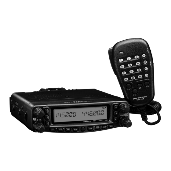
QUAD BAND FM TRANSCEIVER
FT-8900R
O
M
PERATING
ANUAL
VERTEX STANDARD CO., LTD.
4-8-8 Nakameguro, Meguro-Ku, Tokyo 153-8644, Japan
VERTEX STANDARD
US Headquarters
10900 Walker Street, Cypress, CA 90630, U.S.A.
YAESU EUROPE B.V.
P.O. Box 75525, 1118 ZN Schiphol, The Netherlands
YAESU UK LTD.
Unit 12, Sun Valley Business Park, Winnall Close
Winchester, Hampshire, SO23 0LB, U.K.
VERTEX STANDARD HK LTD.
Unit 5, 20/F., Seaview Centre, 139-141 Hoi Bun Road,
Kwun Tong, Kowloon, Hong Kong
Advertisement
Table of Contents

Related Manuals for Yaesu FT-8900R


Summary of Contents for Yaesu FT-8900R
- Page 1 4-8-8 Nakameguro, Meguro-Ku, Tokyo 153-8644, Japan VERTEX STANDARD US Headquarters 10900 Walker Street, Cypress, CA 90630, U.S.A. YAESU EUROPE B.V. P.O. Box 75525, 1118 ZN Schiphol, The Netherlands YAESU UK LTD. Unit 12, Sun Valley Business Park, Winnall Close Winchester, Hampshire, SO23 0LB, U.K.
-
Page 2: Table Of Contents
Introduction ... 1 Specifications ... 2 Accessories & Options ... 3 Supplied Accessories ... 3 Optional Accessories ... 3 Installation ... 4 Preliminary Inspection ... 4 Installation Tips ... 4 Safety Information ... 5 Antenna Considerations ... 6 Mobile Installation ... 8 Transceiver Installation ... -
Page 3: Introduction
Watts of power output on the 29/50/144 MHz Amateur bands and 35 Watts on the 430 MHz band. The high power output of the FT-8900R is produced by its RD70HVF1 Power MOS FET amplifier, with a direct-flow heat sink and thermostatically-controlled cooling fan maintain- ing a safe temperature for the transceiver’s circuitry. -
Page 4: Specifications
2 kΩ 10 kΩ Double-conversion superheterodyne 45.05 MHz/450 kHz (Left band), 47.25 MHz/450 kHz (Right band) Better than 0.2 µV Better than 0.16 µV 12 kHz/30 kHz 2 W @ 8 Ω for 5% THD 4-16 Ω FT-8900R Operating Manual... -
Page 5: Accessories & Options
Packet Interface Cable Availability of accessories may vary. Some accessories are supplied as standard per local requirements, while others may be unavailable in some regions. Consult your Yaesu dealer for details regarding these and any newly-available options Connection of any non-Yaesu- approved accessory, should it cause damage, may void the Limited Warranty on this appa- ratus. -
Page 6: Installation
Do not install the transceiver on top of another heat-generating device (such as a power supply or amplifier), and do not place equipment, books, or papers on top of the FT-8900R. Avoid heating vents and window locations that could expose the transceiver to excessive direct sunlight, especially in hot climates. -
Page 7: Safety Information
The FT-8900R is an electrical apparatus, as well as a generator of RF (Radio Frequency) energy, and you should exercise all safety precautions as are appropriate for this type of device. These safety tips apply to any device installed in a well-designed amateur radio station. -
Page 8: Antenna Considerations
NTENNA ONSIDERATIONS The FT-8900R is designed for use with antennas presenting an impedance of near 50 Ohms at all operating frequencies. The antenna (or a 50 Ohm dummy load) should be connected whenever the transceiver is turned on, to avoid damage that could otherwise result if trans- mission occurs accidentally without an antenna. - Page 9 The use of the shortest possible length of the highest quality coaxial cable that fits within your budget will ensure the best performance from your FT-8900R. FT-8900R Operating Manual...
-
Page 10: Mobile Installation
NSTALLATION The FT-8900R must only be installed in vehicles having a 13.8 Volt negative ground elec- trical system. Mount the transceiver where the display, controls, and microphone are easily accessible, using the supplied MMB-36 mounting bracket. The transceiver may be installed in almost any location, but should not be positioned near a heating vent nor anywhere where it might interfere with driving (either visually or mechani- cally). -
Page 11: Mobile Power Connections
– it is there to protect you, your transceiver, and your vehicle’s electrical system. Never apply AC power to the power cable of the FT-8900R, nor DC voltage greater than 15.8 Volts. When replacing the fuse, only use a 15-A fast-blow type. Failure to observe these safety precautions will void the Limited Warranty on this product. -
Page 12: Base Station Installation
TNC, if it is designed for multiple-radio use, by connecting the TNC “Radio 1” port to the 1200 bps lines on the FT-8900R, and the “Radio 2” port to the 9600 bps lines. The pin connections of the Data connector are shown below. - Page 13 Right band, or Left band: The Paket Transmitting Band is fixed on the Main band). If you have trouble getting your FT-8900R to respond correctly during packet operation, check to be certain that you do not have Menu #26 (PCKT S) set to the wrong data rate, and/or Menu #27 (PCKT B) set to the wrong receiving band.
-
Page 14: Front Panel Controls & Switches
“Hyper” memory bank. Press the appropriate button momentarily to recall the desired “Hyper” memory. ONTROLS KEY2 430 MHz 850 MHz 29 MHz FT-8900R Operating Manual & S WITCHES 144 MHz ... 50 MHz... - Page 15 Scan Skip List or Preferential Scan List. [ SET ] Key Press this key momentarily to enter the Set (“Menu”) mode. Press and hold in this for 1/2 second to transfer the contents of the “Main band” VFO into a Memory register. FT-8900R Operating Manual...
- Page 16 Press and hold in this for 1/2 second to activate Priority Channel Scanning. Key Mode “2” ([ TONE ] Key ) Press this key momentarily to change the Tone Squelch mode: ENC (CTCSS Encoder), ENC.DEC (CTCSS Tone Squelch), or DCS (DCS) operation. & S ONTROLS FT-8900R Operating Manual WITCHES...
- Page 17 When the “right” band is set to be the “Main” band in the VFO mode, press this knob to enable rapid tuning (in 1 MHz steps) using this knob. Press and hold in this knob for 1/2 second to switch the operating band on the “right” band between 144 MHz and 430 MHz. FT-8900R Operating Manual...
-
Page 18: Lcd
: Middle TX Power Selected : Automatic Power-Off Active : Keypad/DIAL Lock Active : Menu (“Set”) Mode : Key Function Mode is selected to “KEY-2” “Left” Band Memory Channel “Right” Band Frequency “Right” Band S- & PO Meter Icons FT-8900R Operating Manual... -
Page 19: Rear Panel Connections
9 Amperes (continuous duty). Make certain that the Red lead connects to the Posi- tive (+) side of the power source, and that the Black lead connects to the Negative (-) side of the power source. FT-8900R Operating Manual... - Page 20 Press (or hold in) either of these buttons to tune (or scan up or down) the operating frequency or through the memory channels on the “Main” band. In many ways, these buttons emulate the function of the (rotary) “Main” band DIAL knob. ICROPHONE DTMF MICROPHONE MH-48 ENC ... FT-8900R Operating Manual...
-
Page 21: Microphone
“Main” band. In many ways, these buttons emulate the function of the (rotary) “Main” band DIAL knob. Notice: If you replace the microphone from the MH-48 versa, perform Menu #23 (MIC). See page 63 for details. FT-8900R Operating Manual MH-42 B6JS , but the MH-42... -
Page 22: Basic Operation
Hi! I’m R. F. Radio, and I’ll be helping you along as you learn the many features of the FT-8900R. I know you’re anxious to get on the air, but I encourage you to read the “Operation” section of this manual as thoroughly as possible, so you’ll get the most out of this fantastic new transceiver. -
Page 23: Selecting The Frequency Band
1 ) You may select the operating band on the “Main” band by pressing and holding in the microphone’s [ P1 ] key for 1/2 second. 2 ) The FT-8900R may be configured to operate either in a V-V or U-U mode, if needed. VHF-VHF ( V-V ) Operation The FT-8900R may receive very strong signals on the Image frequency, and/or the receiver sensitivity may be somewhat reduced by the combination of the “... -
Page 24: Frequency Navigation
Rotating the DIAL knob allows tuning in the pre-programmed steps established for the current operating band. Clockwise rotation of the DIAL knob causes the FT-8900R to be tuned to- ward a higher frequency, while counter-clockwise rotation will lower the operating frequency. -
Page 25: Transmission
“Main” frequency field on the display. Changing the Transmitter Power Level You can select from among a total of four transmit power levels on your FT-8900R. To change the power level, press the [ LOW ] key to select one of four power settings. These... -
Page 26: Advanced Operation
20/25/50 kHz per step, any number of which may be important to your operating require- ments. The FT-8900R is set up at the factory with different default steps on each operating band which probably are satisfactory for most operation. However, if you need to change the channel step increments, the procedure to do so is very easy;... -
Page 27: Display Brightness
The FT-8900R display illumination has been specially engineered to provide high visibility with minimal disruption of your “night vision” while you are driving. The brightness of the display is manually adjustable, using following procedure: 1. Press the [ SET ] key momentarily to enter the Set mode. -
Page 28: Audio Muting
4. Press and hold in the “Main” band DIAL knob for 1/2 second to save the new setting and exit to normal operation. 5. Finally, rotate the SQL knob fully clockwise. PERATION UDIO UTING RF S QUELCH FT-8900R Operating Manual... -
Page 29: Repeater Operation
The FT-8900R includes a number of features which make repeater operation simple and enjoyable. Your FT-8900R has been configured, at the factory, for the repeater shifts customary in your country. For the 50 MHz band, this usually will be 1 MHz, while the 144 MHz shift will be 600 kHz;... -
Page 30: Manual Repeater Shift Activation
If you just have one “odd” split that you need to program, don’t change the “de- fault” repeated shifts using this Menu Item! Enter the transmit and receive fre- quencies separately, as shown on page 33. PERATION EPEATER HIFT FT-8900R Operating Manual CTIVATION... -
Page 31: Ctcss/Dcs Operation
“ENC.DEC” to appear. When “ENC.DEC” appears, this means that the Tone Squelch system is active, which mutes your FT-8900R’s receiver until it receives a call from another radio sending out a matching CTCSS tone. This can help keep your radio quiet until a specific call is received, which may be helpful while operating in congested areas. -
Page 32: Dcs Operation
CTCSS to control access to the repeater, but don’t pass it along when transmitting. If the S-Meter deflects, but the FT-8900R is not passing audio, repeat steps “1” through “4” above, but rotate the “Main” DIAL knob so that “ENC” appears - this will allow you to hear all traffic on the channel being received. -
Page 33: Tone Search Scanning
When this happens, it may be that the other station is not sending any tone. You can press the [ SCN ] key to halt the scan at any time. Tone Scanning works either in the VFO or Memory modes. FT-8900R Operating Manual CTCSS/DCS O EARCH... -
Page 34: Regular Memory Channel Operation
EMORY PERATION The FT-8900R provides a wide variety of memory system resources. These include: Regular Memory Channels, which made up of: 799 “Standard” memory channels, numbered “001” through “799.” Six Home channels, providing storage and quick recall of one prime frequency on each operating band. - Page 35 Whenever you recall a memory which contains independently-stored transmit and receive frequencies, the “ [ FT-8900R Operating Manual EMORY EMORY HANNEL ] ”...
-
Page 36: Memory Operation
Once you have recalled a particular memory channel, you may easily tune off that channel, as though you were in the “VFO” mode. 1. With the FT-8900R in the “MR” (Memory Recall) mode, select the desired memory channel. 2. Now press and hold in the [ V/M ] key for 1/2 second; the “... -
Page 37: Home Channel Memory
2. Press and hold in the “left” [ V/M ] key while turning the radio on. 3. Rotate the “right” DIAL knob to select the (F-5 M-ONLY MODE), then press the [ SET ] key momentarily. To return to normal operation, repeat the above steps. FT-8900R Operating Manual EMORY EMORY HANNEL... -
Page 38: Hyper Memory Mode
EMORY PERATION The FT-8900R usually stores, into memory, the operating frequency and some aspects of operating status (such as CTCSS/DCS data, repeater shift, power level etc.). However, the “Hyper Memory” Mode allows you to store the total current configuration of the radio into a special “Hyper”... -
Page 39: Scanning
The FT-8900R allows you to scan just the memory channels, the entire operating band, or a portion of that band. It will halt on signals encountered, so you can talk to the station(s) on that frequency, if you like. Scanning operation is basically the same in each of the above modes. Before you begin, take a moment to select the way in which you would like the scanner to resume scanning after it halts on a signal. -
Page 40: Vfo Scanning
5. To cancel scanning, press the [ SCN ] key momentarily again (or press the microphone’s PTT key). When you start scanning, the FT-8900R will be changing frequency in the up- ward direction. If you want to change direction of the scan while it is underway, rotate the DIAL knob one click in the opposite direction (in this case, one click counter- clockwise). -
Page 41: Memory Scanning
1/2 second twice to select “OFF” (the “Skipped” channel will, of course, still be acces- sible via manual channel selection methods using the DIAL knob in the MR mode, whether or not it is locked out of the scanning loop). FT-8900R Operating Manual EMORY CANNING... -
Page 42: Preferential Memory Scan
CANNING Preferential Memory Scan The FT-8900R also allows you to set up a “Preferential Scan List” of channels which you can “flag” within the memory system. These channels are designated by a “ ” icon when you have selected them, one by one, for the Preferential Scan List. -
Page 43: Programmable (Band Limit) Memory Scan
Tuning and canning will now be limited within the just- programmed range. 6. Five pairs of Band Limit memories, labeled L1/U1 through L5/U5 are available. You therefore can set upper and lower operation limits on a number of bands, if you like. FT-8900R Operating Manual IMIT EMORY CANNING... -
Page 44: Priority Channel Scanning Dual Watch
3. Press and hold in the [ HM ] key for 1/2 second to activate the VFO Priority mode. The display will remain on the VFO frequency, but every five seconds the FT-8900R will check the Priority Channel (memory channel) for activity. -
Page 45: Smart Search
2 ) You may activate the Smart Search operation on the “Main” band by press and hold the microphone’s [ P2 ] key. 3 ) You may activate the Smart Search operation on the “left” and “right” bands at the same time. FT-8900R Operating Manual MART EARCH... -
Page 46: Arts : Auto Range Transponder System
5. Press the “Main” band DIAL knob momentarily. You will observe the “OUT.RNG” dis- play on the LCD. ARTS operation has now commenced. 6. Every 25 seconds, your radio will transmit a “polling” call to the other station. When that ANGE RANSPONDER FT-8900R Operating Manual YSTEM... -
Page 47: Cw Identifier Setup
12. Press the “Main” band DIAL knob momentarily, then rotate the “Main” band DIAL knob to select “TX ON” (to enable the CW identifier). 13. Press the “Main” band DIAL knob momentarily to save the setting and exit to normal operation. FT-8900R Operating Manual ANGE RANSPONDER YSTEM... -
Page 48: Dtmf Autodialer Operation
DTMF A UTODIALER 16 DTMF Autodialer memories are available on the FT-8900R. These DTMF Autodialer memories can store up to 16 digits of a telephone number for, repeater autopatch or other uses. To load DTMF Autodialer memories, use following procedure: 1. - Page 49 3. Press the “Main” band DIAL knob momentarily, then rotate the “Main” band DIAL knob to select the desired time (50/250/450/750/1000 ms). 4. Press and hold in the “Main” band DIAL knob for 1/2 second to save the new setting and exit to normal operation. FT-8900R Operating Manual UTODIALER PERATION...
-
Page 50: Internet Connection Feature
NTERNET The FT-8900R can be used to access the repeater which is configured to provide access to the Vertex Standard WIRES 1. Press the “left” VOL knob momentarily to activate the WIRES™ access capability. The “INT ON” will appear for 2 seconds at the “Main” band frequency display. The “int”... - Page 51 9 (to establish the link to the Internet link repeater). 10. To disable the Internet link feature, press the “left” VOL knob again. To return to WIRES , recall Menu #17 (INET) then set it to “INT. COD.” FT-8900R Operating Manual ONNECTION EATURE...
-
Page 52: Miscellaneous Settings
“switch-off” time (between 1 and 12 hours in 0.5 hours increments), or OFF. 4. Press and hold in the “Main” band DIAL knob for 1/2 second to save the new setting and exit to normal operation. ETTINGS IMER UTOMATIC OWER FT-8900R Operating Manual... -
Page 53: Programming The Key Assignment
ROGRAMMING THE Default FT-8900R key functions have been assigned to Microphone’s [ P1 ] / [ P2 ] / [ P3 ] / [ P4 ] buttons ( MH-48 , [ ACC ] / [ P ] / [ P1 ] / [ P2 ] buttons: MH-42 be changed by the user, if you wish to utilize another function on one of these keys. -
Page 54: Fm Bandwith & Mic Gain Control
To restore the normal (higher) microphone input level and normal (15 kHz) receiver band- width, select “WIDE” in step 3 above. This feature is ignored on the “right” band and 29 MHz band on the “Left” band. ETTINGS & MIC G ONTROL FT-8900R Operating Manual... -
Page 55: Dcs Code Inversionm
4. Press and hold in the “Main” band DIAL knob for 1/2 second to exit to normal operation. Remember to restore the default setting to “TRX N” (Encoder; Normal, Decoder; Normal) when done. FT-8900R Operating Manual ISCELLANEOUS DCS C NVERSION... -
Page 56: Cross Band Repeater Operation
ROSS The FT-8900R can be set up to operate as a full-featured cross-band repeater via a simple Menu procedure. This feature is useful for emergency portable work in a remote area, and for cross-band linking. However, remember these points before using the cross-band repeater function: Check the amateur radio rules and regulations for your country to ensure that this type of operation is permitted. -
Page 57: Reset Procedure
MEMORY RESET: Clears the Regular Memory settings to factory defaults. Clears all memories and other settings to factory defaults. ALL RESET: 4. Press the [ SET ] key momentarily to complete the reset procedure, once you have made your selection in step 3. FT-8900R Operating Manual ESET ROCEDURE... -
Page 58: Cloning
LONING You can transfer all data stored in one FT-8900R to another FT-8900R by utilizing the handy “Cloning” feature. This requires a user-constructed Cloning cable which connects the DATA jacks on the two transceivers, as shown below. To clone from one transceiver to another, use the following procedure: 1. - Page 59 FT-8900R Operating Manual...
-
Page 60: Menu Set Mode
The FT-8900R Set (Menu) mode, already described in parts of many previous chapters, is easy to activate and set. It may be used for configuration of a wide variety of transceiver parameters, some of which have not been detailed previously. Use the following procedure to activate the Set (Menu) mode: 1. - Page 61 Reducing the MIC Gain (and Deviation). X-RPT Switches the Cross-Band Repeater feature on and off. Enables/disables the AM mode. AUT.AM Selects the receiving mode. FT-8900R Operating Manual Available Values OFF/0.5H - 12H IN RNG/ OUTRNG BND ON/ BNDOFF BEP.ON/ BEP.OFF SFT.ON/ SFT.OFF...
- Page 62 Default: BEP. ON Menu #6 [ CLK.SFT ] Function: Shifting of CPU clock frequency. Available Values: SFT. ON/SFT.OFF Default: SFT.OFF This function is only used to move a spurious response “birdie,” should it fall on a desired frequency. FT-8900R Operating Manual...
- Page 63 Menu #13 [ DTMF D ] Function: Setting of the DTMF Autodialer Delay Time. Available Values: 50MS/250MS/450MS/750MS/1000MS Default: 450MS FT-8900R Operating Manual DCS CODE 023 025 026 031 032 036 043 047 051 053 054 065 071 072 073 074 114 115 116 122...
- Page 64 See page 48 for more details. Available Values: d-1 ~ d-16 Default: d-1 Menu #20 [ KEY.MOD ] Function: Selects the key functions for the “right” band function switches. Available Values: KEY1/KEY2 Default: KEY1 FT-8900R Operating Manual access.
- Page 65 Function: Stores an Alpha-Numeric “Tag” for a memory channel. See page 33 for details. Menu #26 [ PCKT S ] Function: Sets the transceiver’s circuitry for the Packet baud rate to be used. Available Values: 1200bps/9600bps Default: 1200bps FT-8900R Operating Manual...
- Page 66 Note: This Menu Item can be set independently on both the “left” and “right” bands. Menu #33 [ RPT.MOD ] Function: Sets the Repeater Shift Direction Available Values: RPT.OFF/RPT. –/RPT. + Default: RPT.OFF (SIMP) Note: This Menu Item can be set independently on both the “left” and “right” bands. FT-8900R Operating Manual...
- Page 67 The audio is not routed (internal and external speakers are both off). INT.EXT: The audio is routed to both the internal and external speakers. INT: The audio is routed to the internal speaker only (external speaker is off). FT-8900R Operating Manual...
- Page 68 CTCSS TONE FREQUENCY ( Hz ) 67.0 69.3 82.5 85.4 100.0 103.5 123.0 127.3 151.4 156.7 171.3 173.8 189.9 192.8 210.7 218.1 250.3 254.1 FT-8900R Operating Manual 71.9 74.4 77.0 79.7 88.5 91.5 94.8 97.4 107.2 110.9 114.8 118.8 131.8 136.5 141.3 146.2 159.8 162.2 165.5...
- Page 69 Menu #46 [AUT. AM ] Function: Selects the receiving mode. Available Values: AUTO/OFF Default: AUTO (AM in Aeronautical Band, FM elsewhere) FT-8900R Operating Manual...
- Page 70 FT-8900R Operating Manual...
- Page 71 1. Changes or modifications to this device not expressly approved by VERTEX STANDARD could void the user’s authorization to operate this device. 2. This device complies with part 15 of the FCC Rules. Operation is subject to the following two conditions; (1) this device may not cause harmful interference, and (2) this device must accept any interference including interference that may cause undesired operation.
- Page 72 Copyright 2003 VERTEX STANDARD CO., LTD. All rights reserved No portion of this manual may be reproduced without the permission of VERTEX STANDARD CO., LTD. Printed in Japan. 0311F-GY...
Need help?
Do you have a question about the FT-8900R and is the answer not in the manual?
Questions and answers