Table of Contents
Advertisement
Quick Links
Advertisement
Table of Contents

Related Manuals for OTT Lufft WS Series

Summary of Contents for OTT Lufft WS Series
- Page 1 WS Series Smart Weather Sensors Operational Manual...
- Page 2 70736 Fellbach Germany +49 711 51822 -0 met-info@otthydromet.com www.otthydromet.com All rights reserved. All content is the intellectual property of OTT HydroMet. Reprinting, duplication and translation (even as excerpts) are only permitted with the prior written consent of OTT HydroMet. Subject to technical change.
-
Page 3: Table Of Contents
Table of contents Scope of supply Order numbers and variant code Product variants Accessories and spare parts About this manual Other applicable documents and software General signs and symbols Explanation of warnings General safety instructions Intended use Potential misuse Personnel qualification Operator obligations Personnel obligations Correct handling... - Page 4 7.1.2 Choosing a site 7.1.3 Fastening 7.1.4 Aligning to north 7.1.5 Setting rain gauge Electrical installation 7.2.1 Electrical connections 7.2.2 Supply voltage 7.2.3 RS485 Interface 7.2.4 Connecting ISOCON-UMB converter 7.2.5 Installing surge protection 7.2.6 Connecting external sensors Commissioning for UMB data format Set up device Configuration and testing 8.2.1...
- Page 5 11.2 Checking rain gauge 11.3 Updating firmware Troubleshooting 12.1 Fault elimination Repair 13.1 Customer support Notes on disposing of old devices Technical data 15.1 General technical data 15.2 Electrical data 15.3 Dimensions and weight 15.4 Measuring range and accuracy <5>...
-
Page 6: Scope Of Supply
1 Scope of supply The following items are included with delivery: – Smart weather sensor – Connection cable 10 m <6>... -
Page 7: Order Numbers And Variant Code
2 Order numbers and variant code 2.1 Product variants Variant Order number WS200-UMB 8371.U01 WS300-UMB 8372.U01 WS301-UMB 8374.U01 WS302-UMB 8374.U10 WS310-UMB 8374.U13 WS400-UMB 8369.U01 (EU), 8369.U01-NA (US, CA), 8369.U02 (UK) WS401-UMB 8377.U01 WS500-UMB 8373.U01 WS501-UMB 8375.U01 WS502-UMB 8375.U10 WS510-UMB 8375.U13 WS600-UMB 8370.U01 (EU), 8370.U01-NA (US, CA), 8370.U02 (UK) WS601-UMB... -
Page 8: About This Manual
3 About this manual 3.1 Other applicable documents and software The following documents contain further information on installation, maintenance and calibration: – User Manual Smart Weather Sensors – Operating Manual UMB ISO Converter ISOCON – Operating instructions surge protection The following documents and software can be downloaded at www.lufft.com: –... -
Page 9: Explanation Of Warnings
3.3 Explanation of warnings To avoid personal injury and material damage, you must observe the safety information and warnings in the operating manual. The warnings use the following danger levels: WARNING WARNING This indicates a potentially hazardous situation. If the hazardous situation is not avoided, it may result in death or serious injuries. -
Page 10: General Safety Instructions
4 Do not change or convert the product in any way. 4 Do not perform any repairs yourself. 4 Get OTT HydroMet to examine and repair any defects. 4 Ensure that the product is correctly disposed of. Do not dispose of it in household waste. -
Page 11: Health Hazards
4.7 Health hazards 4.7.1 Risk of electrical shock Live parts can cause electric shocks in the event of contact. 4 Never take measurements on live electrical parts. 4 Never touch live electrical parts. 4.7.2 Health hazard due to electromagnetic radiation The devices with percipitation radar (WS400-UMB, WS600-UMB, WS700-UMB, WS800-UMB) generate an electromagnetic field that can be harmful to health and can cause cardiac pacemakers to malfunction. -
Page 12: Working At Roadside
4.8.3 Working at roadside The device can be installed on a mast at the roadside. Special safety regulations apply to prevent accidents and injuries. 4 Observe the safety regulations for working at the roadside and in the vicinity of the road carriageway. 4.9 Certification 4.9.1 Europe, USA and Canada CE (EU) - Page 13 Unauthorized modification or changes to this wireless communication equipment will void the right to use it. Changes or modifications to this unit not expressly approved by the party responsible for compliance will void the user’s authority to operate the equipment. Any change to the equipment will void the FCC grant. IC (CA) Canadian Radio Interference-Causing Equipment Regulation, ICES- 001 This device complies with Industry Canada license-exempt RSS stan- dard(s).
-
Page 14: Product Description
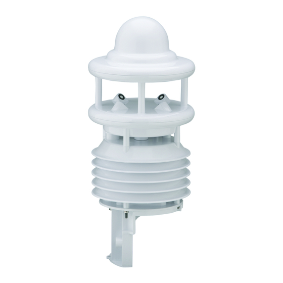
5 Product description 5.1 Design and function The smart weather sensors can be used for the acquisition of a variety of measurement variables, as used for example for environmental data logging in road traffic management systems. Depending on the model, each device has a different combination of sensors for the various measurement variables. -
Page 15: Transport, Storage, And Unpacking
6 Transport, storage, and unpacking 6.1 Unpacking 4 Carefully remove the product from the packaging. 4 Check that the delivery is complete and undamaged. 4 If you find any damage or if the delivery is incomplete, then immediately contact the supplier and manufacturer. -
Page 16: Installation
7 Installation 7.1 Mechanical installation 7.1.1 Required tools and aids The following tools and aids are required: – open-end or ring spanner, SW 13 – compass 7.1.2 Choosing a site WARNING Risk of injury due to improper installation! If the mast or the device is installed improperly, damage to the device and injury to people may result. 4 Ensure that the mast stands on a stable subsurface. - Page 17 > 5 m > 4.5 m > 1 m Installation near the road, WS600-UMB If the device is used to observe the weather for road and traffic control systems, carry out the following installation steps: 4 Install the device at the top of the mast at least 4.5 m above the ground. If there are no moving objects in wider circumference of the device, a lower installation height is possible.
-
Page 18: Fastening
7.1.3 Fastening The mounting bracket is designed to be installed on top of a mast with a diameter of 60 – 76 mm. Mounting bracket Nut with washer Spring Mast 4 Loosen the nuts. 4 Push the device onto the top of the mast from above. 4 Tighten the nuts evenly until they touch the springs but the device can still be moved easily. -
Page 19: Setting Rain Gauge
4 Position the device in such a way that the south and north wind sensors are aligned with the fixed point of reference in the north. 4 Tighten both nuts with 3 revolutions. The magnetic North Pole displayed by the compass differs from the Geographic North Pole. When aligning the device, the declination (variation) at the location must be taken into account. -
Page 20: Supply Voltage
There is an 8 pole screw connector on the underside of the device. This serves to connect the supply voltage and the interfaces via the connection cable. Pin assignment Number Color Assignment White Supply voltage ground and SDI-12_GND for device version > 41 Brown Positive supply voltage (through 2.5 A fuse where required)* Green... -
Page 21: Rs485 Interface
7.2.2.1 Limitations in 12 V mode If the heating is operated on 12 V DC, account must be taken of the functional restrictions in winter operation. A heating voltage of 24 V DC is recommended to guarantee full heating duty. 7.2.2.2 Limitations with supply voltage below 12 V When operating devices from device version 037 with a supply voltage lower than 12 V DC, the fan is not switched on independent of the fan operating mode. -
Page 22: Connecting External Sensors
7.2.6 Connecting external sensors External temperature and precipitation sensors can be connected to the device. The connection uses the standard connector plug of the device and the external sensor will be connected at the end of the delivered cable. All external sensors are unipolar, so any connection sequence can be chosen. -
Page 23: Commissioning For Umb Data Format
4 If several smart weather sensors are operated on a UMB network, assign a unique device ID to each sensor. 8.2 Configuration and testing For configuration and testing OTT HydroMet Fellbach GmbH provides the proprietary software ConfigTool.NET. ConfigTool.NET can also be used to update the firmware of the device. -
Page 24: Factory Settings
8.2.1 Factory settings The device is delivered with the following settings: Specification Value Class ID 7 (cannot be modified) Device ID 1 (gives address 7001h = 28673d) 200 (fixed address since firmware 6.8) Baudrate 19200 RS485 protocol Binary Calculation interval 10 measurements Local altitude 8.3 Configuration using UMB binary protocol... -
Page 25: Configuration Using Older Versions Of Configtool.net
4 Select the Search Type Temporary UMB Communication. 4 Select the Device class WSx-UMB. 4 Click on the Start button and restart the device (power off / on). ð ConfigTool.NET establishes a connection (ID 1 or ID 200) within a few seconds and reads the channel list. ð... -
Page 26: General Settings
8.3.4 General settings Parameter Description Device-ID Factory setting: 1 Assign the IDs for the devices in ascending order. Description To differentiate the devices enter a description, e.g. the location. Baudrate Transmission speed of the RS485 interface Factory setting: 19200 DO NOT change for operation with ISOCON-UMB. Protocol Communication protocol of the device: UMB-Binary, UMB-ASCII, SDI-12, MODBUS- RTU, MODBUS-ASCII, Terminal-Mode, XDR... -
Page 27: Energy Management
8.3.5 Energy management The energy consumption of the device can be adapted to the circumstances of the installation by setting the following parameters: Parameter Description Operation mode The power consumption of the device can be adjusted to the properties of the individual installation. - Page 28 – The radar rain sensor of the following devices is not working continuously: WS800-UMB, WS700-UMB, WS600- UMB, WS400-UMB. The sensor is activated once per minute for one second. If precipitation is detected, it remains turned on until the end of the event. Otherwise the sensor is deactivated again after this second. –...
-
Page 29: Configuring External Sensors
8.3.6 Configuring external sensors The device must be configured for the selected type of external sensor to enable the correct evaluation of the measurement data. 4 Select the external sensor. If data is requested from the channels of the currently unselected sensor type, the device responds with "invalid channel". - Page 30 Parameter Description Altitude Enter the local altitude in meters here for the correct calculation of relative air pressure (referenced to sea level). Air pressure offset Absolute offset on the measurement in the unit indicated in the parameter description field. Air pressure interval Time in minutes for the minimum, maximum and average value calculation interval.
- Page 31 The other parameters, e.g. evaporation or correction factors, can be used to adapt the precipitation detection to special local conditions. They should only be modified after consultation with OTT HydroMet Fellbach GmbH, as they have a major influence on the functioning and accuracy of the sensor.
- Page 32 8.3.7.6 Reset precipitation quantity To reset the accumulated absolute precipitation quantity, proceed as follows: 4 Click the reset symbol in the ConfigTool.NET software, top right of the window header. 4 Select the Target to reset. Parameter Description Device Currently used device Class Class of devices All devices connected to the UMB network...
-
Page 33: Testing
8.3.7.8 Lightning sensor settings Parameter Description Lightning interval Time in minutes for minimum, maximum and average value calculation. 8.4 Testing The functions of the device can be tested with the ConfigTool.NET software by polling various channels. 4 Click on the desired channel. Example of measurement polling The ConfigTool.NET software is provided for test and configuration purposes only. -
Page 34: Commissioning For Sdi-12 Data Format
9 Commissioning for SDI-12 data format The devices can be operated with various protocols, e.g. XDR and UMB-ASCII 2.0. Further information on the protocols can be found in the User Manual Smart Weather Sensors. 9.1 Set up device Preconfigured smart weather sensors with the SDI-12 protocol are available on inquiry. The communication in the SDI-12 mode of the smart weather sensor is conforming to the standard defined in "SDI-12 A Serial-Digital Interface Standard for Microprocessor-Based Sensors Version 1.3 January 12, 2009"... -
Page 35: Command Set
9.3 Command set The commands listed below are available for devices of the smart weather sensors. The composition of the minimal and the full basic data set depends on the variant of the device in question. The same applies to the availability of the additional measurement commands (aM1!, aC1!, etc.). Due to the applied measurement processes the devices measure continuously in normal operation mode. - Page 36 Command Function Details aMC1! ... aMC8! Measurement (assignment of values as for aMn! see aM1! ... aM8! commands), transmit values with CRC Concurrent measurement, full basic data set see aM1! aC1! ... aC8! Concurrent measurement, assignment of values as for see aM1! ... aM8! aMn! commands, partly extended data sets aCC! Concurrent measurement, transmit values with CRC see aM!
-
Page 37: Data Messages
Command Function Details aXVd! Read device version Address configuration The UMB device-ID and SDI-12 address are connected. The different address ranges and the fact that UMB IDs are integer numbers, while SDI-12 addresses are ASCII characters, have to be considered. The SDI-12 address is built from the UMB device ID as follows: UMB device ID 1 (default) corresponds to SDI-12 address ‘0’... -
Page 38: Additional Measurement Commands
Example: M request from a WS600-UMB 00009<CR><LF> 9 measurement values are available. 0D0! 0+13.5+85.7+1017.0+2.5+3.7<CR><LF> Air temperature 13.5 °C, rel. humidity 85.7 %, rel. air pressure 1017 hPa avg. wind speed 2.5 m/s, max wind speed 3.7 m/s. 0D1! 0+43.7+9.8+60+4.4<CR><LF> Wind direction 43.7° wet bulb temperature 9.8 °C, type of precipitation 60 (rain), precipitation intensity 4.42 mm/h. 9.5 Additional measurement commands The following additional measurement commands are available: –... - Page 39 Example: Buffer Assignment Additional Measurement Commands M1 / C1: Temperature Further information can be found in the User Manual Smart Weather Sensors. Device configured for measurement values in metric units (°C): Measurement value UMB channel Minimum Maximum Buffer ‘0’ Air Temperature (act) -50.0 60.0 Air Temperature (min)
-
Page 40: Message Device Identification
9.6 Message device identification The device responds to the identification request with following message (): Example: SDI-12 device address ‘0’ 013Lufft.deWSx00ynnn x: device type (4, 5, 6, 2, 3 ) y: Metric / US units (m = metric, u = US) nnn: Software version Example: WS600-UMB, configured for imperial US units 013Lufft.deWS600u022... - Page 41 Sensor status codes: Sensor status Code UNGLTG_KANAL E2_CAL_ERROR E2_CRC_KAL_ERR FLASH_CRC_ERR FLASH_WRITE_ERR FLASH_FLOAT_ERR MEAS_ERROR MEAS_UNABLE INIT_ERROR VALUE_OVERFLOW CHANNEL_OVERRANGE VALUE_UNDERFLOW CHANNEL_UNDERRANGE BUSY Other sensor status Generally each sensor has two status values, one for the direct value and another for the measurement value buffer used for the evaluation of the average, minimum, and maximum values.
-
Page 42: Commissioning For Modbus Format
10 Commissioning for MODBUS format The devices can be operated with various protocols, e.g. XDR and UMB-ASCII 2.0. Further information on the protocols can be found in the User Manual Smart Weather Sensors. 10.1 Set up device Preconfigured smart weather sensors with the MODBUS protocol are available on inquiry. With the MODBUS communication protocol, the smart weather sensors can be simply integrated into a PLC environment. -
Page 43: Modbus Functions
10.4 MODBUS functions Further information can be found in the User Manual Smart Weather Sensors. For the smart weather sensors, the functions of conformance class 0 and 1 have been implemented, which operate at register level. Starting with device version 227 / firmware version v60 additional coil functions are available. Command Function Comment... - Page 44 When using the metric unit system the first three blocks can supply all data required with one request. There is no difference in the register assignment between the product variants. If, dependent on the variant, some value is not available, this will be indicated by setting the register to the error value. The following tables mainly show average values.
- Page 45 Register Register Value Range Scaling factor Comment number address (UMB channel) signed/unsigned Values independent of the unit system Relative humidity (avg.) Factor 10, s – Relative air pressure (avg.) Factor 10, s – Wind direction (min.) Factor 10, s – Wind direction (max.) Factor 10, s –...
-
Page 46: Status And Type Coding
Register Register Value Range Scaling factor Comment number address (UMB channel) signed/unsigned Wind speed kts (avg.) Factor 10, s – Wind speed standard deviation Factor 100, s Standard deviation values are available after the first request. Wind speed standard deviation Factor 100, s Standard deviation values are available after... -
Page 47: Maintenance
4 Clean the operation of the fan (except for WS200- UMB). Annually 4 Have a calibration check performed (except for OTT HydroMet WS200-UMB). 11.2 Checking rain gauge The function of the rain gauge is influenced by pollution of the funnel or the tipping bucket mechanism. The cleaning of the rain gauge depends on the local conditions and seasons (with falling leaves, pollen, etc.) and... -
Page 48: Updating Firmware
4 Unlock funnel by turning it to the left and lift it off. 4 Clean funnel, specially the sieve slots. 4 Check the inside of the rain gauge for pollution, especially for spider webs and insects. 4 Clean the rain gauge with a soft cloth/brush and water, if necessary. 4 Check the tipping bucket for pollution. -
Page 49: Troubleshooting
12 Troubleshooting 12.1 Fault elimination Fault Possible cause Measures Device does not allow polling or Device does not work properly 4 Check the power supply. does not respond 4 Check the interface connection. Device does not allow polling or Incorrect device ID is applied 4 Check if the correct device ID is does not respond assigned. - Page 50 When the error value 55h (85d) is transmitted, this value is 0 %. If the device permanently transmits values below 50 %, this may mean that there is a fault. Device transmits an unknown – 4 Report any malfunction to the error value representative of OTT HydroMet. <50>...
-
Page 51: Repair
13 Repair 13.1 Customer support 4 Have repairs carried out by OTT HydroMet service personnel. 4 Only carry out repairs yourself if you have first consulted OTT HydroMet. 4 Contact your local representative: www.otthydromet.com/en/contact-us 4 Include the following information: – instrument model –... -
Page 52: Notes On Disposing Of Old Devices
In accordance with the German Electrical and Electronic Equipment Act (ElektroG; national implementation of EU Directive 2012/19/EU), OTT HydroMet takes back old devices in the Member States of the European Union and disposes of them in the proper manner. The devices that this concerns are labeled with the following symbol:... -
Page 53: Technical Data
15 Technical data 15.1 General technical data Specification Value Fastening Stainless steel bracket for mast with diameter 60 – 76 mm Housing Plastic (PC) Protection class III (SELV) Protection type IP66 Operating temperature range -50 to +60 °C Storage temperature range -50 to +70 °C Humidity range 0 to 100 % 15.2 Electrical data Mode... -
Page 54: Dimensions And Weight
Variant Current consumption Power input - heating WS600-UMB 1.7 A 40 VA at 24 V DC WS700-UMB WS800-UMB WS601-UMB 833 mA 20 VA at 24 V DC 15.3 Dimensions and weight WS200-UMB, 800 g WS300-UMB, 1000 g Ø150 mm Ø150 mm WS301-UMB, 1300 g WS302-UMB, 1300 g Ø150 mm Ø150 mm <54>... - Page 55 WS310-UMB, 1300 g WS400-UMB, 1300 g Ø150 mm Ø150 mm WS401-UMB, 1500 g WS500-UMB, 1200 g Ø150 mm Ø164 mm <55>...
- Page 56 WS501-UMB, 1500 g WS502-UMB, 1500 g Ø150 mm Ø150 mm WS510-UMB, 1500 g WS600-UMB, 1500 g Ø150 mm Ø150 mm <56>...
- Page 57 WS601-UMB, 1700 g WS700-UMB, 1500 g Ø164 mm Ø150 mm <57>...
-
Page 58: Measuring Range And Accuracy
15.4 Measuring range and accuracy WS200-UMB – – – – – – WS300-UMB – – – – – – WS301-UMB – – – – – WS302-UMB – – – – – WS310-UMB – – – – – WS400-UMB – – –... - Page 59 Air temperature Specification Value Measurement process Measuring range -50 °C to +60 °C Resolution 0.1 °C (-20 °C to +50 °C), otherwise 0.2 °C Sensor accuracy +/-0.2 °C (-20 °C to +50 °C), otherwise +/-0.5 °C (> -30 °C) Sampling rate 1 minute Units °C; °F Humidity Specification Value Measurement process Capacitive Measuring range 0 to 100 % RH Resolution...
- Page 60 Air pressure Specification Value Measurement process MEMS sensor - capacitive Measuring range 300 to 1200 hPa Resolution 0.1 hPa Accuracy +/-0.5 hPa (0 °C to +40 °C) Sampling rate 1 minute Units Wind speed Specification Value Measurement process Ultrasonic Measuring range 0 to 75 m/s except WS601-UMB: 0 to 30 m/s Resolution 0.1 m/s Accuracy...
- Page 61 Wind direction Specification Value Measurement process Ultrasonic Measuring range 0 to 359.9° Resolution 0.1° Accuracy < 3° (> 1 m/s) RMSE Response threshold 0.3 m/s Internal sampling frequency 15 Hz Instantaneous value 1 sec / 10 sec Output rate for average and peak gust values 1 min – 10 min (peak calculated from 1 sec-values) Precipitation Specification Value...
- Page 62 Compass Specification Value Measurement process Integrated electronic compass Measuring range 0 to 359.9° Resolution 1.0° Accuracy +/- 10° Sampling rate 5 minutes Global radiation Specification Value Measurement process Thermopile pyranometer Measuring range 0.0 to 2000.0 W/m Resolution < 1 W/m Sampling rate 10 seconds Specification Value WS301-UMB...
- Page 63 External temperature sensor WT1/WST1 Specification Value Measurement process Measuring range -40 °C to +80 °C Resolution 0.25 °C Sensor accuracy +/-1 °C (WST1: +/-0.3 °C between -10 °C to +10 °C) Sampling rate 1 minute Units °C; °F External rain gauge WTB100 Specification Value Measurement process Rain gauge with bounce-free reed contact (normally closed) Liquid precipitation resolution 0.2 mm / 0.5 mm (adjustable by reduction ring) Precipitation types...
- Page 64 Contact Information...
Need help?
Do you have a question about the Lufft WS Series and is the answer not in the manual?
Questions and answers