
Subscribe to Our Youtube Channel
Summary of Contents for Haas Automation SR-100
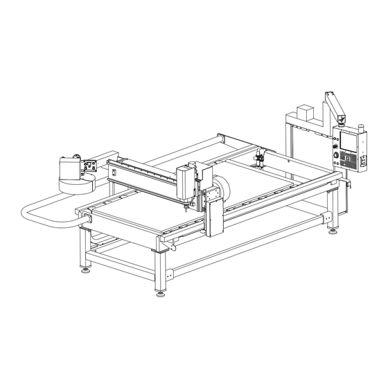
- Page 1 Sheet Router (SR-100) Operator’s Addendum 96-0317 Rev F ©2012 Haas Automation, Inc. March 2012...
- Page 3 afety Read and Follow all safety warnings - Familiarize yourself with the safety section of the Operator’s Manual. Be aware of the other people around you in the shop; lying chips can seriously injure people who may not be a safe distance away.
-
Page 4: Installation
A photoelectric beam is used to stop the machine should personnel or equip- ment enter the protected area. This system will also stop the machine should a large quantity of machining chips pass through the beam. If this happens, change the set-up or machining process to avoid this condition. 1. - Page 5 Power Connection The SR-100 can operate on either 3-phase 208VAC or single-phase 240VAC. Connect the incoming power lines as shown. 3-Phase Connection Single-Phase Connection #12-10 Jumper Line Load Line Load Spindle Taper Size ISO 30, Use HSD USA Inc. pull stud P/N 0804H0009 only.
- Page 6 2. Apply a permanent thread locking compound to the pull stud. 3. Tighten the pull stud into the toolholder to a torque of 62 Nm (46 ft-lbs). 4. Follow the instructions provided with the thread locking compound regarding necessary cure time before the toolholder is used. oving the heet outeR...
- Page 7 Shipping Bracket Three shipping brackets are used with the SR-100. One is located on the bridge to prevent the spindle from moving along the bridge. One bracket is attached to each bridge column to secure the bridge to the table to prevent the bridge from moving during shipping.
- Page 8 90° as shown in the following illustration. peRatoR uaRd The operator guard is not installed on the SR-100 when shipped. 1. Remove the four screws from each end of the machine. NOTE: Be sure that the guard spacers remain in place.
- Page 9 WARNING The electric safety guard must be set up before jogging any axis. The SR-100 comes with a photoelectric beam and relector for the operator side of the machine. Once this system is set up the machine will halt should personnel or equipment enter the protected area.
- Page 10 Use a precision bubble level with each division equal to 0.0005 inch per 10 inches, or .05 mm per meter, or 10 seconds per division. Before starting, check the accuracy of your level. Set it on the table on the X-axis and record the reading.
-
Page 11: Operation
If the SR-100 is powered up with no tool in the spindle, Alarm 131 (Tool Not Clamped) will appear in addition to Alarm 102. Both alarms can be cleared us- ing the Reset button. -
Page 12: Maintenance
Spindle Every day, when the spindle is started up for the irst time, let it warm up slowly without load. This ensures that the bearings reach their running temperature gradually, and that the bearing races expand evenly. The following warming up cycle is recommended, to be performed with the tool holder in place but without actually machining (no load): •... - Page 13 The Z-axis ballscrew grease itting is located between the Z-axis linear guide grease ittings on the operator side of the spindle. SR-100 Grease Fittings Gear Racks, X and Y Axes Periodically inspect for chips, dust and debris, and clean with the air nozzle.
Need help?
Do you have a question about the SR-100 and is the answer not in the manual?
Questions and answers