Table of Contents
Advertisement
Instructions for Installation, Operation & Service
Manufa c t u re r :
Distrib u to r :
Na me & m o d e l nu mbe r :
Mod. 401
Descri p ti o n :
SPECIALIST COMPONENT SUPPLIER TO THE CARAVAN, RECREATION VEHICLE AND MARINE INDUSTRIES
Doc.No.:
DometicUSA Item:
SMEV401-402AUS
CU401I1840B00AU
Date: 2010-03
Models 401 & 402 with Gas Electric Hob Option
Caravan and Recreation Hob, Grill and Oven
S MEV s rl .
C AME C P t y Lt d
4 7 -63 R e m in g t o n D rive
D a nd e non g S o ut h V i c 3 1 7 5
Aust ral i a
Te le ph one : 0 3 -9799 645 5
Fa cs i mi l e : 0 3 - 9 7 9 9 6 4 6 6
e -m a i l : c a me c @ c a m e c . c om.au
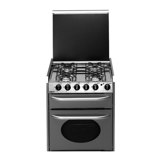
Hotplate, Grill & Oven
A co mp a c t p ro pane - fu e l l e d O ve n, Grill & Hotplate ideally
s u it e d for c a rav an, ma ri n e and recreational use .
Ig n i t i o n of burne rs i s e le c tronic .
Mod. 402
Hotplate & Grill
REV 8
Advertisement
Table of Contents

Summary of Contents for Camec SMEV 401
- Page 1 REV 8 Instructions for Installation, Operation & Service Models 401 & 402 with Gas Electric Hob Option Caravan and Recreation Hob, Grill and Oven Manufa c t u re r : S MEV s rl . Distrib u to r : C AME C P t y Lt d 4 7 -63 R e m in g t o n D rive D a nd e non g S o ut h V i c 3 1 7 5...
-
Page 2: Table Of Contents
CONTENTS GENERAL SAFETY INSTRUCTIONS WARINGS APPLIANCE SPECIFICATIONS OPERATION CHOICE OF BURNERS APPLIANCE IGNITION GAS FLOW SETTINGS GRILL OPERATION OVEN OPERATION ABNORMAL OPERATION CLEANING HOTPLATE AND ELECTRIC ELEMENT CONTROL KNOBS BURNERS TRIVET (PAN SUPPORT) SHELVES AND GRILL TRAY INSTALLATION AND CONNECTION 9 -13 ROOM VENTILATION FITTING THE APPLIANCE INTO THE CABINET... -
Page 3: General Safety Instructions
GENERAL SAFETY INSTRUCTIONS IF YOU SMELL GAS: 1) OPEN WINDOWS AND IMMEDIATELY EVACUATE ALL PEOPLE OUT OF CARAVAN, CAMPERVAN, MOBILE HOME, ETC 2) DO NOTTOUCH ELECTRICAL SWITCHES,LIGHT MATCHES,SMOKE OR DOANYTHING THAT COULD IGNITE GAS. 3) EXTINGUISH ANY OPEN FLAMES. 4) CLOSE CYLINDER OR TANK SUPPLY VALVES. DO NOT TURN ON VALVES UNTIL LEAK HAS BEEN CORRECTED. -
Page 4: Appliance Specifications
APPLIANCE SPECIFICATIONS NOMINAL HOURLY GAS CONSUMPTION & INJECTOR PROPANE GAS BURNER INJECTOR ORIFICE Mj/h FRONT LH 0.72 mm FRONT RH 0.72 mm REAR LH 0.72 mm OPTIONAL ELECTRIC REAR LH 230-240 V A.C. 800 WATTS REAR RH 0.57 mm GRILL 0.62 mm OVEN 0.57 mm... -
Page 5: Operation
OPERATION FIG. 4 MOD. 401 MOD. 402 CONTROL PANEL ( Fig. 4 ) Semi-rapid Burner or Electric Element (12) control knob Semi-rapid Burner (11) control knob Semi-rapid Burner (10) control knob Right auxiliary Burner (13) control knob Grill Burner control knob (14) control knob Oven Burner control knob Oven lamp switch Oven Rotisserie switch (optional) -
Page 6: Choice Of Burners
CHOICE OF BURNER Choose the burner suitable for the pan dimensions making sure the burner flame does not extend beyond the pan base (Fig.6). BURNER PAN DIAMETER FIG. 6 MINIMUM MAXIMUM Auxiliary burner 6 cm 16 cm (13, fig. 5) Semi-rapid burner 16 cm 22 cm... -
Page 7: Grill Operation
GRILL OPERATION Before using the grill for the first time, let it run at maximum temperature for the duration of 15 minutes. For best results it is advisable to preheat for a few minutes the grill. CAUTION: WHEN GRILLING, GRILL COMPARTMENT DOOR MUST BE LEFT COMPLETELY OPEN. -
Page 8: Abnormal Operation
ABNORMAL OPERATION The following are considered to be abnormal operations and require servicing by an Authorized serviceman: · Yellow tipping of burner flame · Sooting up of cooking utensils · Burners not igniting properly · Burners failing to remain alight ·... -
Page 13: Installation And Connection
INSTALLATION AND CONNECTION NOTE: ALL INSTALLATION SHOULD BE CARRIED OUT BY AUTHORIZED TRADE’S PERSONS ONLY IN ACCORDANCE WITH THESE INSTRUCTIONS, RELEVANT FEDERAL AND STATE REGULATIONS, AND WITH THE REQUIREMENTS OF SECTION 5, 6.2 AND 6.3 OF AS5601 / AG601 - 2002 “GAS INSTALLATIONS” AND AS/NZS3000 “ELECTRICAL INSTALLATIONS”... -
Page 14: Fitting The Appliance Into The Cabinet
FITTING THE APPLIANCE INTO THE CABINET THE CABINET MUST HAVE THE DIMENSIONS INDICATED IN FIG. 1. FIG. 1 MINIMUM DISTANCES TO BE OBSERVED FROM WALLS (Fig. 2.) a) Side clearance from the edge of the burner to any vertical wall 200mm. b) Overhead clearance from the Appliance Hob to a Range-hood or Shelves 600 mm Note: Stainless Steel Vent 60mm high must be installed under front bottom edge at ALL times. - Page 15 INFLAMMABLE MATERIALS MUST BE KEPT AWAY FROM THE APPLIANCE. ATTACH THE FRAME TO THE CABINET WITH THE SCREWS PROVIDED ( Fig. 3 ). FIG. 3 NOTE: WHEN INSTALLING THE MODEL 401THE 60mm HIGH STAINLESS STEEL VENT SUPPLIED WITH THE MODEL 401 MUST BE INSTALLED UNDER THE FRONT BOTTOM EDGE OF THE APPLIANCE.
-
Page 16: Connection Of Gas
CONNECTION OF GAS (Propane) TO THE APPLIANCE NOTE: ALL INSTALLATION SHOULD BE CARRIED OUT BY AUTHORIZED TRADE’S PERSONS ONLY IN ACCORDANCE WITH THESE INSTRUCTIONS, RELEVANT FEDERAL AND STATE REGULATIONS, AND WITH THE REQUIREMENTS OF SECTION 5.12, 6.2 AND 6.3 OF AS 5601 / AG601 “GAS INSTALLATIONS”, PUBLISHED BY THE AUSTRALIAN GAS ASSOCIATION. -
Page 17: Testing
MAKE SURE ALL CONNECTIONS ARE MADE TO THE CORRECT TERMINALS. NOTE: UNDER NO CIRCUMSTANCES CAN 12 VOLTS d.c. BE CONNECTED TO A 230-240 VOLTS a.c. TERMINAL, OR 230-240 VOLTS a.c. MAINS BE CONNECTED TO THE 12 VOLTS d.c. TERMINALS. THIS WOULD CAUSE DESTRUCTION OF THE ELECTRIC COMPONENTS OR WOULD BE DANGEROUS FOR THE USER. -
Page 18: Maintenance
MAINTENANCE HOB BURNER HEAD REMOVAL / REPLACEMENT 1) Remove trivet (pan support) by pulling up from hob. 2) Remove screws from appropriate burner head disk. Remove head disk. 3) Remove burner by lifting straight up, taking care not to damage the thermocouple and ceramic igniter. -
Page 19: Setting And Adjusting Of Oven Thermostat
4) From the underside of the hotplate, remove the appropriate thermocouple lead from the gas cock. 5) From the underside of the hotplate, remove the appropriate gas cock clamp by unscrewing the (2) screws. 6) Remove the gas cock from the manifold. 7) Replace/ refit in reverse procedure. -
Page 20: Who To Contact
WHO TO CONTACT For service of your SMEV appliance, firstly contact your selling agent. CAMEC Pty Ltd Distrubuted by: HEAD OFFICE VICTORIA 47-63 Remington Drive Dandenong South,Vic, 3175 Australia. Phone: (03) 9799 6455 Fax: (03) 9799 6466 Email: camec@camec.com.au NEW SOUTH WALES BRANCH ½...
Need help?
Do you have a question about the SMEV 401 and is the answer not in the manual?
Questions and answers