Table of Contents
Advertisement
Quick Links
Advertisement
Table of Contents

Related Manuals for Carrier 50NC Series


Summary of Contents for Carrier 50NC Series
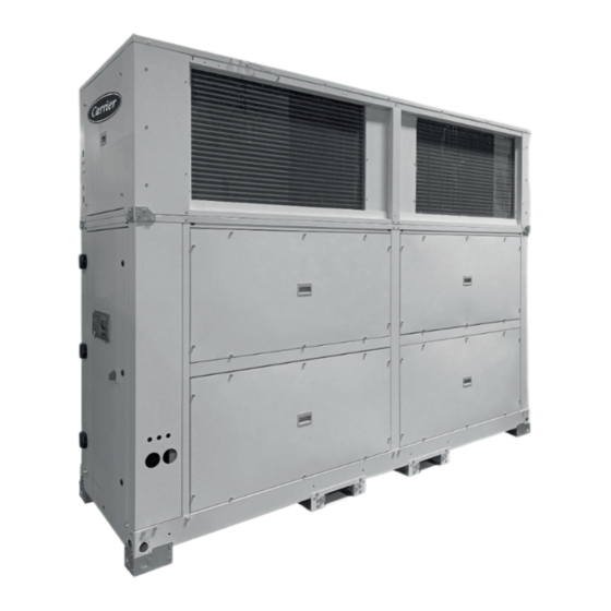
- Page 1 I N S TA L L AT I O N , O P E R AT I O N A N D M A I N T E N A N C E I N S T R U C T I O N S Vertical autonomous heat pumps 50NC 022-118 Nominal cooling capacity 34.3 - 81.5 kW...
-
Page 2: Table Of Contents
SUMMARY - INTRODUCTION ..................................3 - SAFETY ADVISE ................................... 3 2.1. General safety advise ............................... 3 2.2 Safety standards for refrigerant ............................4 - POSSIBLE TYPES OF ASSEMBLIES ..........................5 - OPERATION LIMITS ................................6 - TRANSPORT ..................................6 5.1 Transport .................................... 6 5.2 Receipt of goods ................................ -
Page 3: Introduction
1 - INTRODUCTION 50NC reversible heat pumps are vertical air-to-air units These units are equipped with hermetic scroll-type compressors consisting of two modules (indoor and outdoor), which can be in tandem design, as well as electronic plug-fans for the outdoor supplied in Package or Split version. -
Page 4: Safety Standards For Refrigerant
2 - SAFETY ADVISE Do not modify or bypass any of the safety guards or Type of refrigerant R-410A switched in the system. Global warming potential (GWP) 2.088 Caution: Before intervening in the unit, Flammability class verify that the main power supply to the unit is cut off... -
Page 5: Possible Types Of Assemblies
3 - POSSIBLE TYPES OF ASSEMBLIES Available confi gurations Mixing box (CS assembly) Depending on the airfl ow direction: Mixing box with for air renewal and free-cooling managed by the electronic control of the unit. The box incorporates Indoor circuit supply - Outdoor circuit supply two interlocked dampers with a servomotor. -
Page 6: Operation Limits
CARRIER Route de Thil 01120, MONTLUEL, France Important: The serial number must be used in all UK Importer: Toshiba Carrier UK Ltd, Porsham Close, Roborough, Plymouth, PL6 7DB correspondence regarding the unit. Contient des gaz à effet de serre fluorés \ Contains fluorinated greenhouse gases regulated by the Kyoto protocol... - Page 7 5 - TRANSPORT Transport and handling / Transport et manutention / Transporte y manipulación 50NC 038 / 042 2175 1640 1560 058 / 064 / 074 / 086 2175 2900 2820 038 / 042 1440 1640 1560 058 / 064 / 074 / 086 1440 2900 2820...
-
Page 8: Handling
6 - HANDLING These machines must be unloaded and positioned by Crane lifting a specialist handling company using the appropriate, These holes, located at the standardized tools. ends of the crossbars, are the Important: In the Split version the interior and exterior modules only points that can be used to are supplied separately. - Page 9 6 - HANDLING Indoor module (Split version) Before dragging the module, the skids and guides must be disassembled, and a series of operations must be carried out The crossbeams of the indoor module are equipped with support to reattach them to the crossbars. They should be reattached feet for transport with a forklift.
-
Page 10: Positioning And Installation.10
7 - POSITIONING AND INSTALLATION 7.1 Choice of location Threaded rods When choosing the location, whatever may be the selected (not supplied) fashion, the following precautions must be taken into consideration: ● It is mandatory to comply with norm EN 378-3 on Safety and Environmental Requirements. -
Page 11: Antivibrators Assembly (Silent-Blocks)
7 - POSITIONING AND INSTALLATION 7.3 Antivibrators assembly (silent-blocks) In the event of assembling directly on silent-blocks to the ground, it is recommended that a template of the unit’s footprint with the anchoring points of the silent-blocks be made (consult the fi xing for antivibrators in paragraph 7.5) With the help of the crane or the forklift truck, the unit will be raised to a suffi... -
Page 12: Sound Level
If necessary, a study must be commissioned to an acoustic technician. Note: The acoustic insulating cover for compressor (optional) achieves a sound level reduction of approximately 2 dB(A). Sound power level (LW) Package unit 50NC series 63 Hz 125 Hz 250 Hz... -
Page 13: Centres Of Gravity, Weight And Reactions In The Supports
7 - POSITIONING AND INSTALLATION 7.5 Centres of gravity, weight and reactions in the supports Models with 1 circuit Package unit 50NC Centre of gravity Distances Reactions in the supports Weight series (mm) (mm) (kg) (kg) Coming soon 985 1.295 786 987 1.295 786 Split unit: Outdoor module 50NC... - Page 14 7 - POSITIONING AND INSTALLATION 7.5 Centres of gravity, weight and reactions in the supports Models with 2 circuits Package unit 50NC Centre of gravity Distances Reactions in the supports Weight series (mm) (mm) (kg) (kg) R1 R2 R3 R4 R5 R6 1.326 434 965 1.234 786 1.069 190 230 133 179 214 123...
-
Page 15: Recommended Service Clearance
7 - POSITIONING AND INSTALLATION 7.6 Recommended service clearance Important: This is the minimum space required for maintenance operations and access inside the unit. Depending on the assembly selected for the unit and the characteristics of the installation site, a larger space around it may be required to ensure proper air circulation and therefore the correct operation of the unit. - Page 16 7 - POSITIONING AND INSTALLATION 7.6 Recommended service clearance Important: This is the minimum space required for maintenance operations and access inside the unit. Depending on the assembly selected for the unit and the characteristics of the installation site, a larger space around it may be required to ensure proper air circulation and therefore the correct operation of the unit.
-
Page 17: Electrical Connection
8 - ELECTRICAL CONNECTION 8.1 Installation norms Wiring must be selected based on: ● The maximum power input, taking into account all the options Important: All connections in the site are the it features (refer to the technical brochure and the nameplate). responsibility of the installer. -
Page 18: 50Fc" Electronic Control
8 - ELECTRICAL CONNECTION 8.5 "50FC" electronic control Dual locks can function as hinges or can be used to remove the door. Check that the locks are not "50FC" electronic control is basically comprised of a control blocked. Open them with a 4 mm Allen wrench (in board, a graphic terminal, an user terminal (optional) and an anti-clockwise direction). - Page 19 8 - ELECTRICAL CONNECTION Customer connection The following connections must be made on site by the customer: Outdoor Indoor Mixing box module module (option) 50NC Connections 022 to 028 038 to 042 058 to 086 106 to 118 Main power Standard unit 5G 25A x 10 mm 5G 25A x 10 mm...
-
Page 20: Sensors Connection By The Costumer
8 - ELECTRICAL CONNECTION 8.6 Sensors connection by the costumer Connection of the outdoor humidity probe (optional) The costumer must connect on-site the following probes: ● Ambient NTC (standard) or RS485 (optional). The outdoor humidity probe (optional) replaces the outdoor ●... - Page 21 8 - ELECTRICAL CONNECTION Connection of the CO air quality probe Outdoor installation There are diff erent options: ● Ambient air quality probe. ±0.3 3.54 “ ±0.11 ● Return air quality probe (duct-mounted). ● Probe installed on the master unit of the shared network (SHRD).
-
Page 22: Refrigerant Connection
9 - REFRIGERANT CONNECTION This chapter is intended for units supplied in the Split version. Maximum distances between modules Recommendations ● The maximum equivalent length of the refrigerant line is 50 The following considerations should be taken into account: meters, with a maximum geometric height of 40 meters when ●... - Page 23 ● The diameter of the pipes is as follows: Optional service valves and refrigerant charge ● The outdoor module can incorporate service valves. These 50NC series 022 028 038 042 058 064 074 086 106 118 valves must remain closed until the refrigerant connection Liquid line 5/8”...
-
Page 24: Fans And Air Ducts
10 - FANS AND AIR DUCTS 10.1 Checks in the EC plug-fans which aff ect the available pressure and the fl ow. The location of discharge and aspiration grilles must be studied carefully ● The 50NC units are equipped with electronic variable speed to avoid air recirculation and the transmission and generation plug-fans in both the outdoor and indoor modules. -
Page 25: Condensate Drain
11 - CONDENSATE DRAIN Siphon installation norms Both the outdoor and indoor modules include a pan that collects condensate. Perform the assembly as per the scheme of the attached starting ● Outdoor module: 3/4” M junction threaded, in bronze. diagram: ●... -
Page 26: Safety Elements
12 - SAFETY ELEMENTS High-pressure switch Safeties at the compressors Connected to the compressor discharge, it will stop its operation ● These units have a klixon switch on the compressor discharge when the pressure at that point reaches the setpoint. which stops the operation of the motor when there is excessive heating. - Page 27 12 - SAFETY ELEMENTS Clogged fi lter detector (optional) Smoke detector (optional) A diff erential pressure switch is a device used for detecting the This smoke-detecting station, in accordance with the NF S 61- fi lter clogging level. 961 standard, uses a LED to indicate the installation status, If the probe detects the presence of smoke in the installation, it This pressure switch is installed in the electric cabinet of the stops the operation of the unit and gives the order to open or...
-
Page 28: Factory Options And Accessories
13 - FACTORY OPTIONS AND ACCESSORIES 13.1 Air fi lters 13.2 Stop-drop in the indoor coil ● The unit is shipped as standard with G4 fi lters, mounted in a ● The stop-drop can be installed in the indoor coil. It is holder structure attached to the return of the indoor module. -
Page 29: Heat Recovery Coil
13 - FACTORY OPTIONS AND ACCESSORIES 13.3 Heat recovery coil ● The heat recovery coil (HRC) is located between the main ● The unit’s electronic control manages both the heat recovery indoor coil and the air fi lters (indoor module). coil and the 3-way valve. -
Page 30: Electrical Heaters
● Up to 3 values of total power available for each model: Wall bushing ● The frame provides access to the electrical heaters through 50NC series E0L (Low) E0N (Nominal) E0H (High) the side panel. In the case of 2 frames, they are placed... -
Page 31: Mixing Box (Cs Assembly)
13 - FACTORY OPTIONS AND ACCESSORIES 13.5 Mixing box (CS assembly) ● CS assembly: Mixing box with for air renewal and free- Important: In the Package version, the installer will be cooling managed by the electronic control of the unit. The responsible for the construction of a structural support for the box incorporates two interlocked dampers with a servomotor. -
Page 32: Zoning Of The Airfl Ow
13 - FACTORY OPTIONS AND ACCESSORIES 13.6 Zoning of the airfl ow This option allows the management of the airfl ow of the unit to The installer must carry out the following connections: condition up to 4 diff erent zones with a minimum airfl ow of 35% ●... -
Page 33: Commissioning
14 - COMMISSIONING 14.1 Commissioning Control of the refrigerant charge ● It is advisable to create a detailed layout of the installation, including the position of the unit and all utilized components. ● The Package version is shipped from the factory with an exact This will be greatly benefi... -
Page 34: Possible Problems At Commissioning
14 - COMMISSIONING If the refrigerant charge is lower than required, the suction electrical components, pressure will drop and overheating on the compressor inlets ● signifi cant temperatures in the cooling circuit (see attached will be high. This can cause an interruption in operation due table), to the activation of the refrigerant charge safety device. -
Page 35: Maintenance
15 - MAINTENANCE 15.1 General recommendations ● Check that the doors and panels are properly closed. ● Check the anti-corrosion coatings. To ensure optimal effi ciency and reliability of the equipment and all its functions, we recommend taking out a maintenance contract with the local organization set up by your manufacturer. -
Page 36: Access To The Main Components
The oil type recommended for these units is: Copeland 3MAF 32cST, Danfoss POE 160SZ, ICI Emkarate RL 32CF, Mobil EAL Artic 22CC. The following table indicates the required volume: 50NC series Volume (l) Coming soon 50NC series Volume (l) - Page 37 (t CO2e) for each model: the cooling circuit. Package version: ● Measure the diff erence in the temperature of the pipes at the 50NC series drier inlet and outlet. Charging valve Charge (kg) 2 x 5,65 ● If necessary, replace.
- Page 38 15 - MAINTENANCE Air fi lters fi g. 15.3 Removed the closure ● Depending on the installation conditions, the fi lter aspect must bottom panel be examined to defi ne the cleaning or replacing periodicity. Spare parts should be planned for. The pressure drop data of the technical catalogue are given for clean fi...
- Page 39 15 - MAINTENANCE Plug-fans Condensate drainage pan ● Both the outdoor and indoor modules include a pan that collects condensate. - Outdoor module: 3/4” M junction threaded, in bronze. - Indoor module: 1/2” M junction threaded, in plastic. Indoor module pan drainage Access to the fans of the outdoor module can be eff...
-
Page 40: Control And Analysis Of Breakdowns
16 - CONTROL AND ANALYSIS OF BREAKDOWNS Symptom Cause Solution The evaporation pressure is a) Charge excess a) Collect refrigerant very high in relation to the b) High air temperature b) Verify overheating air inlet c) Compressor suction not airtight c) Verify compressor state and replace d) Cycle reversing valve in middle position d) Check that the valve is not clogged. -
Page 41: Final Shutdown
17 - FINAL SHUTDOWN Shutting down Materials to be recovered for recycling Separate the units from their energy sources, allow them to cool ● Steel then drain them completely. ● Copper ● Aluminium ● Plastics Recommendations for disassembly ● Polyurethane foam (insulation) Use the original lifting equipment. - Page 42 Notes:...
- Page 44 (latest current version) after an assessment conducted by an authorized independent third party. Please contact your sales representative for more information. Order No.: 10790, 10.2023.Supersedes order No.: New Carrier, Montluel, France Manufacturer reserves the right to change any product specifi cations without notice. Printed in the European Union...
Need help?
Do you have a question about the 50NC Series and is the answer not in the manual?
Questions and answers