Table of Contents
Advertisement
Quick Links
Advertisement
Table of Contents

Related Manuals for autosen AG001


Summary of Contents for autosen AG001
-
Page 2: Table Of Contents
Table of contents 1. Preliminary note 2. Safety instructions 3. Intended use 4. Function 5. Installation 6. Electrical connection 6.1 Wiring 6.2 Connection examples 7. Operating and display elements 8. Parameterization 8.1 Starting the parameterization mode 8.2 Parameterization procedure 8.3 Exiting the parameterization mode 8.4 Explanation of parameters 8.4.1 Programming lock 8.5 Explanation of extended parameters... -
Page 3: Preliminary Note
1. Preliminary remark Instructions, technical data, approvals and further information via the QR code on the device / on the packaging or via www.autosen.com. 2. Safety instructions • The device described is installed as a subcomponent in a system. - The security of this system is the responsibility of the creator. -
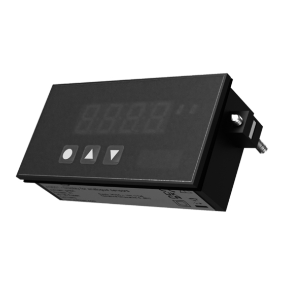
Page 4: Intended Use
6 mm. 4. Function The display AG001 is a 4-digit digital display for DC current signals / DC voltage signals and a visual limit value monitoring via the display. The configuration is done via three front keys. An integrated programming lock prevents unwanted changes of parameters and can be unlocked again via an individual code. -
Page 5: Installation
5. Installation Fig. 1: Installation 1: Gasket 2: Fastener 3: Dimension field *Installation depth including terminal The fastening elements supplied are suitable for wall thicknesses up to 6 mm. Create panel cutout (92 x 45 mm). Remove the fastening elements from the device. Insert the device into the panel cutout. -
Page 6: Electrical Connection
6. Electrical connection The device may only be installed by a qualified electrician. Follow national and international regulations for the installation of electrotechnical equipment. Disconnect the system from the power supply. Connect the device as follows: 6.1. Wiring 24 VDC Fig. -
Page 7: Connection Examples
6.2 Connection examples 4...20 mA AGND 4...20 mA AGND Fig. 3: 2-wire sensor 4...20 mA Fig. 4: 2-wire sensor 4...20 mA with external power supply 0/4...20 mA 0/4...20 mA AGND AGND Fig. 5: 3-wire sensor 0/4...20 mA Fig. 6: 3-wire sensor 0/4...20 mA with external power supply 0...10 V AGND... -
Page 8: Operating And Display Elements
7. Operating and display elements Fig. 9: Operating and display elements Direction keys Programming button Display... -
Page 9: Parameterization
8. Parameterization Parameters can be set before installation and commissioning of the device or during operation. If you change parameters during operation, the functioning of the equipment will be affected. Ensure that there are no malfunctions in the system. During the parameterization process, the device remains in working mode. It continues to perform its monitoring functions with the existing parameter until parameterization is completed. -
Page 10: Exiting The Parameterization Mode
Menu level Advanced menu level Parameter level Parameter level Fig. 10: Menu overview 8.3 Exiting the parameterization mode Parameterization mode is terminated by selecting the RUN menu item on the (extended) menu level and confirming with [●]. Then confirm ULOC again with [●]. (→ 8.4.1. Programming lock) The display automatically saves all adjustments and switches to operating mode if no further key is pressed within 10 seconds. -
Page 11: Programming Lock
Menu level Parameter level Setting the lower range value, offs: Default: 0000 The initial value is adjusted from the smallest to the largest digit with [▲] [▼] and confirmed digit-selectively with [●]. After the last digit, the display changes back to the menu level. -
Page 12: Explanation Of Extended Parameters
8.5 Explanation of extended parameters If the [▲] & [▼] keys are pressed simultaneously for one second during standard parameterization, the display switches to the extended parameterization mode. The operation is the same as in the standard parameterization. Menu level Parameter level Scaling the measurement input limits, EndA: With the help of this function the end value can be scaled to e.g. - Page 13 Menu level Parameter level Assignment (deposit) of key functions, Key: Default: no Here, either a min/max value query or a limit value correction can be stored on the direction keys for the operating mode. If the min/max memory is activated with EHER, the measured min/max values are stored during operation and can be retrieved via the direction keys [▲] [▼].
- Page 14 Menu level Parameter level Function for limit value undercut / limit value overcut, FU-1: Default: hi9h The limit value violation is selected with Louu (for LOW = lower limit value) and HiGH (for HIGH = higher limit value). Derived from "lower limit" = lower limit value and "higher limit"...
- Page 15 Menu level Parameter level Setting the code, CODE: Default: 1234 With this setting it is possible to select an individual code (factory setting 1 2 3 4) for the programming lock. For programming lock / unlock please proceed according to menu item run. Number of additional support points, SPCt: Default: 0 8 additional interpolation points can be defined for the start and end values in...
-
Page 16: Restore Factory Settings
8.6 Restore factory settings To set the device to a defined basic state, the factory settings can be reset as follows: Disconnect the power supply from the device. Press the [●] key and keep it pressed. With the [●] key pressed, connect the device to the power supply and keep the [●] key pressed until the display shows "- - -". -
Page 17: Technical Data
10. Technical data Housing Dimensions 96x48x25 mm (WxHxD), T = 40 mm including plug-in terminal Installation cutout 92.0 x 45.0 +0,8 +0,6 Wall thickness up to 3 mm Mounting Screw elements Material PC (polycarbonate), black, UL94V-0 Sealing material EPDM, 65 Shore, black Protection class Standard IP65 (front), IP00 (rear) Weight... - Page 18 Accuracy Temperature drift 100 ppm / K Measuring time 0.1...10.0 seconds Measuring principle U/F conversion Resolution approx. 18 bit at 1s measuring time Power supply unit 24 VDC ± 10% max. 1 VA Memory EEPROM Data preservation ≥ 100 years at 25°C Environmental conditions Working temperature 0°C...60°C...
-
Page 19: Troubleshooting
11. Troubleshooting Error description Measures The device indicates a permanent • The input has a very large measured value, overflow. check the measuring distance. • If an input with a small sensor signal is selected, it is only connected on one side or the input is open.
Need help?
Do you have a question about the AG001 and is the answer not in the manual?
Questions and answers