Table of Contents
Advertisement
Quick Links
Table of Contents
1. Technical specifications ................................................................................................................... 2
2. Pack contents ............................................................................................................................... 2
3. Description .................................................................................................................................. 3
3.1. Bluetooth® and Wifi control ................................................................................................... 3
3.2. iOs / Android apps ............................................................................................................... 3
3.3. Bluetooth® pairing .............................................................................................................. 3
4. Installation of the Ofix VP ............................................................................................................... 4
4.1. Hydraulic installation ............................................................................................................ 4
4.2. Connection to electricity ........................................................................................................ 6
5. Start up / configuration .................................................................................................................... 6
5.1. Choice of the Vigipool ''central unit'' appliance ............................................................................. 6
5.2. Using the calibration container ................................................................................................ 7
5.3. pH sensor calibration ............................................................................................................ 7
5.4. RedOx sensor calibration ....................................................................................................... 8
5.5. Additional parameters that can be set from the smartphone app: ......................................................... 8
6. Appliance operation ........................................................................................................................ 8
6.1. pH & ORP / T°C measurement ................................................................................................ 8
6.2. Measured value display ......................................................................................................... 9
6.3. Analyser colour codes & alarm messages: ................................................................................... 9
6.4. Reset to zero ...................................................................................................................... 9
7. Association with other appliances ...................................................................................................... 10
8. Maintenance ............................................................................................................................... 11
8.1. pH / ORP sensor maintenance ................................................................................................ 11
A. Declaration of conformity ............................................................................................................. 12
Read these instructions carefully before installing, commissioning and using this product.
MPNT0470 v1.0EN (10/05/2022)
OPERATING INSTRUCTIONS
Connected pH / RedOx / T°C
analyser to be installed on the pipe
Ofix VP
PF10J070
Advertisement
Table of Contents

Subscribe to Our Youtube Channel
Summary of Contents for ccei vigipool Ofix VP
-
Page 1: Table Of Contents
OPERATING INSTRUCTIONS Ofix VP Connected pH / RedOx / T°C analyser to be installed on the pipe PF10J070 Table of Contents 1. Technical specifications ........................2 2. Pack contents ..........................2 3. Description ..........................3 3.1. Bluetooth® and Wifi control ....................3 3.2. -
Page 2: Technical Specifications
Ofix VP v1.0EN OPERATING INSTRUCTIONS 1. Technical specifications Dimensions 185 x 165 x 130 Installation Connection Ø 50mm 12V~ AC 50Hz Power supply voltage 230V/12V transformer included Power consumption Weight 900 g Protection rating IP-54 pH measurement Measurement using a combined electrode - +/- 0.1 Measurement range 5 to 9 Calibration... -
Page 3: Description
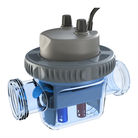
Ofix VP v1.0EN OPERATING INSTRUCTIONS 3. Description • pH, RedOx analysis, water temperature and flow switch • 2 built-in injection nozzles for pH corrector and residual / disinfectant • RGB backlit analysis chamber • User friendly smartphone app • Wifi and Bluetooth connection •... -
Page 4: Installation Of The Ofix Vp
Ofix VP v1.0EN OPERATING INSTRUCTIONS Pairing is only possible via the Vigipool app. Do not attempt pairing from the smartphone's Bluetooth settings. 4. Installation of the Ofix VP 4.1. Hydraulic installation The Ofix VP connected analyser is installed on a 50mm diameter pipe using the supplied union fittings. It is installed down- stream of filtration (after the filter) and must be placed horizontally on a section of pipe that is always pressurised relative to the pool water level, this is to make sure that there is always water in the appliance and that the sensors are always in water. - Page 5 Ofix VP v1.0EN OPERATING INSTRUCTIONS 4.1.2. Connected analyser installation direction Pay close attention to the direction of water flow to guarantee proper use of the appliance and of those connected to it: 4.1.3. Start up At start-up, the analyser must be opened to remove the protective covers from the pH and RedOx sensors. This is done in several steps: 1.
-
Page 6: Connection To Electricity
Ofix VP v1.0EN OPERATING INSTRUCTIONS 4.2. Connection to electricity Installation of this project involves a hazard of electric shocks. We strongly recommend you contract a professional installer. Incorrect installation puts you in danger and may irreversibly damage the product and the equipment connected to it. For safety reasons, and in accordance with the French NF C15-100 standard, the Ofix VP power supply block must be installed •... -
Page 7: Using The Calibration Container
Ofix VP v1.0EN OPERATING INSTRUCTIONS If you want to change the Vigipool ''central unit' appliance, the system must be reset (see ''Re- setting to zero'') 5.2. Using the calibration container 1. Unscrew the general nut and carefully re- move the measuring and injection block from the tank 2. -
Page 8: Redox Sensor Calibration
Ofix VP v1.0EN OPERATING INSTRUCTIONS 5 red flashes = calibration not validated, not taken into account by the appliance: insufficiently stabilised measurement or measurement not compliant 5.4. RedOx sensor calibration Use the 650 mV ORP solution. The filtering must be turned off to calibrate the sensor. 1. -
Page 9: Measured Value Display
Ofix VP v1.0EN OPERATING INSTRUCTIONS The temperature is measured every second. 6.2. Measured value display The LED's built into the appliance visually indicate if the pH and ORP measurements are within acceptable values for effective water treatment. Depending on the two measurements (pH and ORP), the lighting varies according to the following table, used to identify the LED colours depending on the measurements: To indicate an ongoing injection phase, the multi-colour LED will flash while remaining in the colour for the measurement (flashing yellow for example) -
Page 10: Association With Other Appliances
Ofix VP v1.0EN OPERATING INSTRUCTIONS 7. Association with other appliances Ofix VP can be combined with other Vigipool world wireless appliances (referenced with the VP suffix). The association of an appliance with your Ofix VP is carried out when the new element to be added to the eco-system (a dosing pump for example) is switched on. -
Page 11: Maintenance
Ofix VP v1.0EN OPERATING INSTRUCTIONS 8. Maintenance Note that the average sensor service life varies from 6 to 18 months depending on use. A TAC < 100 mg/l reduces the sensor's service life. Sensors are fragile consumables that should be checked by a professional. 8.1. -
Page 12: Declaration Of Conformity
Ofix VP v1.0EN OPERATING INSTRUCTIONS A. Declaration of conformity CCEI S.A.S FR47 403 521 693 declares that the Ofix VP product meets the safety and electromagnetic compatibility requirements of European directives 2014/35/EU and 2014/30/EU. Emmanuel Baret Marseille, on 10/05/2022 Distributor's stamp...
Need help?
Do you have a question about the vigipool Ofix VP and is the answer not in the manual?
Questions and answers