
Related Manuals for FIRVENA ENOCEAN-GWY-MOD


Summary of Contents for FIRVENA ENOCEAN-GWY-MOD
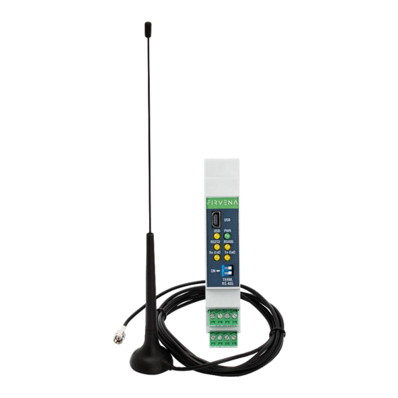
- Page 1 EnOcean to RS 232, 485 Modbus RTU Gateway ENOCEAN-GWY-MOD 868 MHz User Manual V1.16 English...
-
Page 2: Table Of Contents
ONTENTS Contents ................................2 Terms and Abbreviations ........................... 4 Introduction ..............................5 Description ............................5 Hardware Overview ............................ 6 Product conformity and certification ......................6 Technical data ............................. 7 Safety information and warnings ....................... 8 Gateway dimensions (in mm) ........................9 Electrical installation.......................... - Page 3 13.2 Supported RPS telegrams ........................38 13.3 Supported 4BS telegrams ........................38 13.4 Supported VLD telegrams ......................... 42 14 Saving characters for channels descriptions .................... 48 Revision history ..............................49 nOcean to RS 232, 485 Modbus RTU Gateway – User Manual V1.16 / 2024-01-18 / All rights reserved...
-
Page 4: Terms And Abbreviations
Thank you for purchasing our product! We believe in your satisfaction with the product that aligns with the company philosophy of the highest care and precision. In case of interesting ideas and concepts, please contact firvena@firvena.cz www.firvena.com nOcean to RS 232, 485 Modbus RTU Gateway – User Manual... -
Page 5: Introduction
NTRODUCTION 1.1 Description The device ENOCEAN-GWY-MOD is bidirectional gateway which wirelessly receives and controls elements through communication standard EnOcean and then communicates through communication interface RS 232 and RS 485 with the MODBUS RTU protocol. Gateway is designed for wide spectrum of elements (e.g. -
Page 6: Hardware Overview
ARDWARE VERVIEW Front side of gateway for EnOcean / RS 232, RS 485 Modbus RTU has six LED diodes. Green LED diode marked with the symbol PWR is used for indication, if supply voltage is connected. For supply voltage connection, it lights green permanently. Yellow LED diodes indicate communication. -
Page 7: Technical Data
ECHNICAL DATA Category Parameter Value rated voltage 24 V DC (recommended value for power supply) range possibility for power supply 10 – 25 V DC Electrical data own consumption of device 80 mA power consumption 1,92 W protocol MODBUS RTU slave supported functions 3, 6, 16 baudrate... -
Page 8: Safety Information And Warnings
AFETY INFORMATION AND WARNINGS Please follow the general safety regulations. This device may only be installed by a qualified person (accredited electrician) and after reading these instructions. Improper installation can result in health, property or equipment damage. The product meets the general safety regulations. The protection Cover IP 20 allows installation only in normal, dry space. -
Page 9: Gateway Dimensions (In Mm)
ATEWAY DIMENSIONS IN MM nOcean to RS 232, 485 Modbus RTU Gateway – User Manual V1.16 / 2024-01-18 / All rights reserved... -
Page 10: Electrical Installation
LECTRICAL INSTALLATION The device is intended to be used for installation into control cabinet in a DIN rail. After device installation, wires are connected to terminals. Example for connection of stabilized DC supply voltage: Example for connection of communication through serial line RS 232: nOcean to RS 232, 485 Modbus RTU Gateway –... - Page 11 Example for connection of communication through serial line RS 485: Example for connection of communication through USB interface: nOcean to RS 232, 485 Modbus RTU Gateway – User Manual V1.16 / 2024-01-18 / All rights reserved...
-
Page 12: Rs 485 Communication Settings
8 RS 485 COMMUNICATION SETTINGS Balance of idle state of the line RS 485 MODBUS RTU: Communication serial line RS 485 MODBUS RTU in idle state, when no device transmits and all devices are to receive, the line is especially sensitive to induced voltage (faults) that may appear as incoming erroneous data. -
Page 13: Modbus Rtu Communication Description
9 MODBUS RTU COMMUNICATION DESCRIPTION Gateway receives data on frequency 868 MHz during its activity. It checks and processes these data. Valid data are saved into prepared registers. These registers are readable by MODBUS RTU protocol. 9.1 Register map There are a few registers assigned to each gateway in MODBUS RTU protocol. Register map Area Description... -
Page 14: Register Map - Data
9.1.1 Register map – data Each device has 10 registers in which measured and converted values of supported sensors are saved, then there are saved information about signal strength, number of received telegrams, time from the last receiving, and indication of error. Values are converted according to assigned RORG. -
Page 15: Register Map - Id Data
… Value 1 Value 2 Value 3 Value 4 Value 5 Value 6 Signal strength Number of received telegrams Time from the last receiving Error Register map - Error register Value Meaning of value Message Ok The type of sensor is not supported Timeout (10 minutes without received data) (it hasn’t worked for the time being) The position is not occupied 9.1.2 Register map –... -
Page 16: Register Map - Current Changes
Register map – ID data Description RORG FUNC TYPE RORG FUNC TYPE … RORG FUNC TYPE 9.1.3 Register map – current changes To monitor currently received messages quickly, data about currently received messages are reserved in register fields. Registers with the address from 900 to 920 contain currently received message. The stack is available for forty currently received messages. - Page 17 Register map – current changes Description Device number (0-39) (00FF – all new messages are read) Value 1 Value 2 Value 3 Value 4 Value 5 Value Value 6 Signal strength Number of received telegrams Time from the last receiving Error RORG FUNC...
-
Page 18: Register Map - Service Data
Signal strength Number of received telegrams Time from the last receiving Error Device number (0-39) (00FF – all new messages are read) Source ID0 Source ID1 Source ID2 Source ID3 Dest. ID0 Dest. ID1 Dest. ID2 Dest. ID3 RORG FUNC TYPE VALUE1 VALUE2... - Page 19 1014 (Teach-in) ID 2 1015 (Teach-in) ID 3 1016 (Teach-in) RORG 1017 (Teach-in) FUNC – if it is in TEACH -IN supported differently 9999 1018 (Teach-in) TYPE – if it is in TEACH -IN supported differently 9999 1019 (Teach-in) Manufacture ID 1020 (Teach-in) signal strength 1021...
-
Page 20: Register Map - Raw Data
Register map – service data - Address 1011 – Status Value Meaning of value 0x1100 Start without programming 0x1101 Start – new program has error CRC 0x1102 Start – new program is the same as the current one 0x1103 Start reprogramming was successful 0xFFFF Command was executed successfully 0xEEE1... -
Page 21: Register Map - Pressac
2010 ID 0 2011 ID 1 2012 ID 2 2013 ID 3 2014 RORG =0xF6 (0xD5) 2015 DB 0 2016 DB 1 2017 DB 2 2018 DB 3 2019 Status … 2390 Hi byte ID 1, Lo Byte ID 0 2391 Hi byte ID 3, Lo Byte ID 2 2392... -
Page 22: Register Map - Tx
3019 Reserved (0xFFFF for Type 0, Type1) (0 for Type 2) … 3390 ID 3 Hi , ID2 Lo 3391 ID 1 Hi , ID0 Lo 3392 Telegram type (0,1,2) 3393 Power fail (1,0) 3394 Divisor (1,0) 3395 0 (reserved) 3396 Value 1 (Type 0, Type 1, Type 2) 3397... - Page 23 5017 R/W VALUE7 5018 R/W Learn button 5019 Sending 1 - Immediately 2 – For receiving message 1x (must be filled in Destination ID) 3 – For receiving message always (must be filled in Destination ID) 101 – This immediately and next message in sequence in 100ms 102 –...
-
Page 24: Supported Functions
10 S UPPORTED FUNCTIONS It is possible to communicate with gateway in the net MODBUS RTU with following functions: • Function 3 enables to read any registers in its memory range. Available registers return zero. • Function 6 sets values in (adjustable) registers. It is used to set transmitted message and for its sending. - Page 25 A5-02-18 Value1 Temperature +20 … +100 °C (x10) A5-02-19 Value1 Temperature +30 … +110 °C (x10) A5-02-1A Value1 Temperature +40 … +120 °C (x10) A5-02-1B Value1 Temperature +50 … +130 °C (x10) A5-02-20 Value1 Temperature -10 … +41,2 °C (x10) A5-02-30 Value1 Temperature -40 …...
- Page 26 Value2 Supply voltage 0… 5.0V (x10) Value3 Supply voltage availability: 0 – Supply voltage is not supported 1- Supply voltage is supported A5-07-02 Value1 0 – Uncertain of occupancy status … 1 – Motion detect Value2 Supply voltage 0… 5.0 V (x10) A5-07-03 Value1 0 - PIR off …...
- Page 27 Value2 VOC ID 0: VOCT (total) 1: Formaldehyde 2: Benzene 3: Styrene 4: Toluene 5: Tetrachloroethylene 6: Xylene 7: n-Hexane 8: n-Octane 9: Cyclopentane 10: Methanol 11: Ethanol 12: 1 – Pentanol 13: Acetone 14: ethylene Oxide 15: Acetaldehyde ue 16: Acetic Acid 17: Propionice Acid 18: Valeric Acid...
- Page 28 190...209: Stage 0 165...189: Stage 1 145...164: Stage 2 0...144: Stage 3 Value5 Stage 0,1,2,3, (255=AUTO) Value6 Reserved A5-10-02 Value1 Actual temperature 0…+40°C (x10) Value2 Setpoint 0-255 Value3 Slide switch or Slide switch Day/Night 1 – day(sw1) 0- night(sw0) Value4 Turn-switch for fan speed Enum 210...255: Stage Auto 190...209: Stage 0...
- Page 29 A5-10-07 Value1 Actual tempetature 0…+40°C (x10) Value2 reserved Value3 reserved Value4 Turn-switch for fan speed Enum: 210...255: Stage Auto 190...209: Stage 0 165...189: Stage 1 145...164: Stage 2 0...144: Stage 3 Value5 Stage 0,1,2,3, (255=AUTO) Value6 reserved A5-10-08 Value1 Actual tempetature 0…+40°C (x10) Value2 reserved Value3...
- Page 30 A5-10-xx Room Operating Panel Registers Description A5-10-10 Value1 Actual temperature 0…+40°C (x10) Value2 Setpoint 0-255 Value3 Button occupancy 1 – preset 0- released Value4 Humidity 0…100% Value5 Reserved Value6 Reserved A5-10-11 Value1 Actual temperature 0…+40°C (x10) Value2 Setpoint 0-255 Value3 Slide switch or Slide switch Day/Night 1 –...
- Page 31 Value6 1 Failure temperature sensor 10 Actuator obstructed (MVA004 motor failure) 100 Cover open 1000 Batery – change battery next day 1111 + Batery – change battery next day + Cover open + Actuator obstructed + Failure temperature sensor A5-20-04 Value1 Actuator position 0…100 % Value2...
-
Page 32: Supported Rps Telegrams
Flags (16 bits) 8 bits [15:8] Reserved bit7 (MSB) Local Offset Mode 0:Relative; 1:Absolute bit6 Temperature Selection 0:Ambient; 1:Feed bit5 Harvesting Status 0:Not harvesting; 1:Harvesting active bit4 Charge Level 0:Low; 1:Sufficient bit3 Window Open 0:False; 1:True bit2 Radio Error 0:False; 1:True (>= 6 consecutive errors) bit1 Signal Strength 0:Strong;... -
Page 33: Supported 1Bs Telegrams
Value5 Energy Bow: 0 – released; 1- pressed; 2-long push Value6 Number of incoming messages from the last reading of the value 1 (max. 3) F6-02-03 Value1 0x30: Button A0: Set the controller in automatic mode 0x10: Button A1: Set the controller in manually mode and toggles between switch light on and switch light off 0x70: Button B0: Dim light up 0x50: Button B1: Dim light down... -
Page 34: Supported Vld Telegrams
12.4 Supported VLD telegrams D2-01-XX Actuators, Dimmers Registers Description CMD = 0x01 Value1 CMD index = 1 Value 2 Output value: 0: Output value 0% or OFF 1...100: Output value 1% to 100% or ON 101...126: Not used 127: Output value not valid / not applicable Value3 Dim value: 0: Switch to new output value... - Page 35 0: Energy [Ws] 1: Energy [Wh] 2: Energy [KWh] 3: Power [W] 4: Power [KW] 5… 7: Not used D2-03-XX Registers Description D2-03-00 Value1 0-4 ... Reserved 5 ... Button A1 + B0 pressed, energy bow pressed 6 ... 3 or 4 buttons pressed, energy bow pressed 7 ...
- Page 36 1: Blockage mode 2: Alarm mode 3 ... 7:Reserved Value6 Note 1) The same mapping is valid for D2-05-00, D2-05-01, D2-05-02 and D2-05-03. 2) D2-05-03 partial support, only CMD1 to 4. D2-14-40 Multisensor: Temperature, Humidity, XYZ Acceleration, Illumination D2-14-41 Multisensor: Temperature, Humidity, XYZ Acceleration, Illumination, Window Contact Registers Description Value1...
-
Page 37: Supported Msc Telegrams
Value4 Value5 0 …1 Divisor Value6 0 … 1 Power Fail D2-20-12 12.5 Supported MSC telegrams D1-xx-xx MSC telegrams Registers Description D1-03-C1 Value1 Temperature 1 (the most updated) -20… 100 °C (x10) Value2 Temperature 2 (the most updated) -20… 100 °C (x10) Value3 Temperature 3 (the most updated) -20…... -
Page 38: Supported Profiles Of Device (Eep) For Transmitting Data
13 S (EEP) UPPORTED PROFILES OF DEVICE FOR TRANSMITTING DATA Selected RORG protocols are supported for transmitting. Numbers according to EEP are entered to transmitting registers RORG, FUNC and TYPE. Values from registers VALUE 1…7 are converted to format of selected protocol. - Page 39 A5-02-12 Value1 X 10 Temperature -40…40 °C A5-02-13 Value1 X 10 Temperature -30…50 °C A5-02-14 Value1 X 10 Temperature -20…60 °C A5-02-15 Value1 X 10 Temperature -10…70 °C A5-02-16 Value1 X 10 Temperature 0…80 °C A5-02-17 Value1 X 10 Temperature 10…90 °C A5-02-18 Value1 X 10...
- Page 40 2 – valve closed 10 – set point inverse 11 – valve open maintenance + set point inverse 12 – valve closed + set point inverse Value6 0 – nothing 1 – summer mode Value7 0 – RCU 1 – Service on Teach-in 0: Data telegram 1: Learning mode...
- Page 41 LEARNING MODE VARIATION 3 The learning mode for MD15-FTL-HE is in the form query – answer. The gateway makes this process automatically. It is necessary to follow the procedure. 1. Fill in actuator ID to registers for transmitting channels. 2. Fill in RORG, TYPE, FUNC. 3.
-
Page 42: Supported Vld Telegrams
1: Delay Value5 0: Unlock 1: Lock Lock for duration time if time >0, unlimited time of no time specified. Locking may be cleared with „unlock“. During lock phase no other commands will be accepted or executed Teach-in 0: Data telegram 1: Learning mode COM ID 2 Value1... - Page 43 0: Not used 1…15: Dim timer 1 [0,5 … 7,5s / steps 0,5s] Value5 Dim timer 3 - slow 0: Not used 1…15: Dim timer 1 [0,5 … 7,5s / steps 0,5s] Value6 0: Disable taught-in devices (with different EEP) 1: Enable taught-in devices (with different EEP) 0: Over current shut down: static off 10: Over current shut down: automatic restart...
- Page 44 3: Power [W] 4: Power [KW] Value4 Measurement delta to be reported 0...4095: 0...4095 Value5 Maximum time between two subsequent actuator messages MAT Measurement Response messages [10s] 1...255: 10...2550s Value6 Minimum time between two subsequent actuator messages MIT Measurement Response messages[s] 1...255: 1...255s Value7 0: Report measurement: query only...
- Page 45 0: Timer deactivated 1...65534: 0.1...6553.4 s 65535: Does not modify saved value Value4 Delay OFF Timer 0: Timer deactivated 1...65534: 0.1...6553.4 s 65535: Does not modify saved value Value5 External Switch/Push Button (External interface mode) 0: Not applicable 1: External Switch 2: External Push Button 3: Auto detect Value6...
- Page 46 2: Go down (100%), then to POS/ANG 3 … 7:Reserved Value6 LOCK Set/reset locking modes 0: Do not change 1: Set blockage mode 2: Set alarm mode 3 … 6:Reserved 7: Deblockage Value7 Not used Teach-in CMD – 0x02 Value1 CMD = 2 Stop Value 2 Channel address Channel (1)
- Page 47 VLD TEACH-IN PROCESS For learning process VLD, the command UTE is used. D4-XX-XX Registers Description Value1 DB6.7 0b0 Unidirectional communication (EEP operation) 0b1 Bidirectional communication (EEP operation) DB6.6 0b0 EEP Teach-In-Response message expected 0b1 No EEP Teach-In-Response message expected DB6.5 ... DB6.4 0b00 Teach-in request 0b01 Teach-in deletion request 0b10 Teach-in or deletion of teach-in, not specified...
-
Page 48: Saving Characters For Channels Descriptions
14 S AVING CHARACTERS FOR CHANNELS DESCRIPTIONS Short description with lenght 40 characters can be connected to each transmitting (60) and receiving (40) channel. These characters are saved in registers with the address 10000-20000. Description 10000 10001 12 (Length) 10002 R/W „T“... -
Page 49: Revision History
EVISION HISTORY Date Version Description Supported 4BS telegrams (chapter 7.1) 2nd March 2018 V1.3 Supported 4BS telegrams (chapter 8.3) 10th October 2018 V1.4 Repair connection RS 232, text corrections 25th October 2018 V1.5 Enlargement of supported MSC telegrams for PRESSAC 3 channel temperature 17th December 2018 V1.6 Repair of technical information 22nd February 2019...
Need help?
Do you have a question about the ENOCEAN-GWY-MOD and is the answer not in the manual?
Questions and answers