Table of Contents
Advertisement
Quick Links
Advertisement
Table of Contents

Related Manuals for Novexx Solutions XPU

Summary of Contents for Novexx Solutions XPU
- Page 1 USER MANUAL Pallet labeler Edition 02 - 01/2024...
-
Page 2: Table Of Contents
Every time before starting production - 10 Warning notes on the machine - 11 Product description - 12 - 12 Overview Designs - 12 Functionality - 13 Components of the XPU - 15 - 16 Operating controls XPU - 17 Operating components at the printer Connections - 18 Technical data - 20 Options - 23 - 25... - Page 3 User Manual Creating Print Jobs - 61 Transferring a Print Job from a Host by Means of Layout Software - 61 Transferring a Print Job from a Host by Means of a Command file - 62 - 64 Starting a Print Job from an External Memory Medium Starting and Monitoring a Print Job - 66 Error messages...
-
Page 4: Please Note
GENERAL NOTES Validity of this manual and required compliance Naming The entire pallet labeler is hereinafter referred to as the XPU. The XPA 936 print & apply system con- tained in the XPU is referred to below as the printer. Contents... -
Page 5: General Notes
Any obligation to extend these changes to machines previously delivered is excluded. Copyright NOVEXX Solutions retains all rights to this manual and its appendices. Reproduction, reprint or any other type of duplication, including parts of the manual, are permitted only with written approval. - Page 6 FOR YOUR SAFETY Intended use The XPU palett labeler is intended for printing on self-adhesive DIN A5 labels in portrait format and to apply two identical labels at two sides of a loaded palett (see fig. below). Printing method: The labels are printed and dispensed by the integrated print & apply system using the...
-
Page 7: For Your Safety
Palett: As a rule, the - loaded - palett will be moved on a conveyor up to the labeling position in front of the XPU, where it will be stopped. The palett must stand still during the labeling. 5 c m 5 c m Fig. - Page 8 • The service personnel must be acquainted with the functionality of the label dispenser • The system integrator must be acquainted with the functionality of the of the system into which the XPU is being integrated Tasks System integrator...
-
Page 9: Operating Safety Of The Machine
User Manual Any product liability and warranty claims will not be valid unless the machine is operated according to the instructions in the operating manual. Keep product information at hand This user manual ► must remain readily available for operating personnel at a location near to the machine. ►... -
Page 10: Every Time Before Starting Production
User Manual Schutz vor Verletzungen durch mechanische Einwirkung WARNING! Danger of crushing between dispensing edge and applicator pressure plate due to ap- plicator movement! ► If the machine is running or ready for operation, never reach between the applicator and the dispensing edge. ►... -
Page 11: Warning Notes On The Machine
User Manual Warning notes on the machine CAUTION! Warning notes on the machine provide important information for the operating personnel. ► Do not remove warning notes. ► Replace missing or illegible warning notes. Fig. 2: Warning notes on the printer. Warning note Meaning Article no. -
Page 12: Product Description
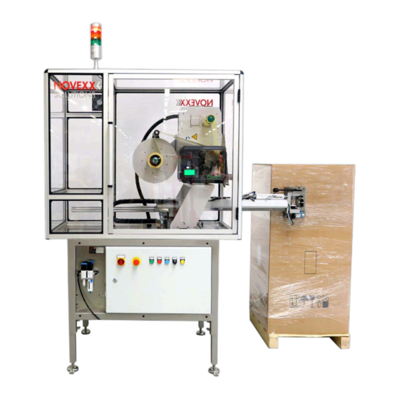
Designs The XPU is available in a righthand (RH) and lefthand (LH) version. Irrespective of wether it is a RH or LH XPU, the operator stands always on the same side of the ma- chine (see fig. below). If the application has to be in accordance with the GS1 standard, a RH machine has to be applied. -
Page 13: Functionality
Fig. 4: XPU LH: The applicator slews to the left to apply the frontal label. Functionality The main function of the XPU palett labeler is printing on DIN A5 labels in portrait format and to apply two identical labels at two sides of a loaded palett. - Page 14 User Manual 5. The applicator moves laterally towards the palett and applies the label. Fig. 6: The first label is attached to the front side of the palett. 6. As soon as the touch down sensors at the applicator foot signal that the label is pressed on, the ap- plicator moves back to the printer dispensing edge.
-
Page 15: Components Of The Xpu
Fig. 8: As the applicator foot (2) moves away from the pallet (5), the light beam of the scanner (1) passes over the barcode (4) on the label (3). Components of the XPU Fig. 9: Components of the XPU. Pos. Name... -
Page 16: Operating Controls Xpu
“Operating components at the printer” on page 17 Signal beacon Dust protection cabin Cabin door Pneumatic service unit Operating controls XPU Fig. 10: Operating controls at the XPU Pos. Name Function Main switch Switches the power supply of the machine on/off. See chapter “Switching the machine on”... -
Page 17: Operating Components At The Printer
User Manual Pos. Name Function REPRINT LABEL button Prints a label without starting an application cycle (e. g. for setting purposes at the printer). The machine must be stopped. Operating components at the printer Fig. 11: Operating components at the printer. Pos. -
Page 18: Connections
User Manual Operating Controls The operation panel of the XPA 93x consists of a graphic display and four keys below the display. The current functions of the keys are displayed by icons (B) above the keys. Fig. 12: Operation panel of the XPA 93x: A Icons that inform about the interface assignment, B Icons that show the key assignment, C Keys, D Standby key, E Remaining ribbon stock. - Page 19 User Manual Compressed air connection Fig. 14: Connect a “PUN 10 x 1,5” pneumatic hose to the service unit at the XPU (1) and to the compressed air supply. Edition 02 - 01/2024 Product description Overview...
-
Page 20: Technical Data
The palett must be able to withstand a lateral force up to 100 N, otherwise the touchdown sensors of the applicator won´t be triggered. Printer • Type: NOVEXX Solutions XPA 936 • Print technology: Thermal transfer printing • Print head type: Corner Edge •... - Page 21 User Manual Fig. 15: Dimensions and stroke length of XPU RH. Fig. 16: Dimensions and stroke length of XPU LH. Edition 02 - 01/2024 Product description Technical data...
- Page 22 User Manual Fig. 17: Dimension drawing XPU. Edition 02 - 01/2024 Product description Technical data...
-
Page 23: Options
When using PP/PE labels or very thin labels, it can be difficult to dispense the labels onto the applica- tor pad. For those cases, an applicator with O-rings is available. The O-rings move with the labels dur- ing dispensing. Fig. 18: O-ring applicator foot at the XPU. Shelf and tilt-out mini keyboard Article number: N101074 When data is not send directly to the printer from a central host, this shelf and tilt-out mini keyboard prepared for use at a PC can be applied. - Page 24 User Manual Fig. 19: XPU with separate PC and keyboard. Edition 02 - 01/2024 Product description Options...
-
Page 25: Parameter Menu Printer
User Manual PARAMETER MENU PRINTER Overview parameter menu The table below gives an overview of the structure of the parameter menu and the parameters it con- tains. Only the parameters printed in red are described here. The parameters printed in black are only rel- evant for service personnel and are therefore described in the Service Manual. - Page 26 User Manual Dispenser Options System DispenseMode At this point appear the submenus Accessauthoriz. with parameters for options if op- Real 1:1 (Operator password) tions are built into the machine. For details refer to the service manual. ├ Dispensingmode (Supervisor password) └...
- Page 27 User Manual Printer Language Printer Language (cont.) Interface PrintInterpret. ├ Command^JM Print interface EasyPlug Setting └ Command^MD/^SD Network ├ Characterfilter ├ IP Addressassign ├ Charactersets ├ IP address ├ EasyPlugerrors ├ Net mask ├ EasyPlugwarning ├ Gatewayaddress ├ Spoolermode ├ Portaddress ├...
- Page 28 User Manual Tools Tools (continued) Info Diagnostic Internal Flash ModelID ├ (Usermodified) ├ Status Printouts [13] [14] Copy from USB ├ Parameter 1 └ Delete Dir ├ Printer Status ├ ... ├ MemoryStatus └ Parameter n ├ Font Status ├ Store Parameters ├...
- Page 29 User Manual Info (continued) Info (continued) Info (continued) System └ CPU board data └ TPH power └ Machine Data ├ CPU identifier ├ Module name ├ Serialnumber ├ FPGAversion ├ Modulepartnumb. ├ Product code ├ Module name ├ Serialnumber ├ Company name ├...
- Page 30 User Manual Info (continued) Info (continued) └ Material rewind Measurements ├ Module name ├ Ribb. rest length ├ Modulepartnumb. ├ Ribbon diameter ├ Serialnumber ├ Ribb. rewinder Ø ├ Productiondate ├ Mat. rewinder Ø ├ CAN MAC address └ Head temperature └...
-
Page 31: Parameter Reference
User Manual Parameter Reference Print contrast Setting range Default setting Step width Easy Plug [1...110] % #!H, #PC2045 CAUTION! The parameter Print contrast affects directly the life durance of the print head. It counts: „The higher the setting of Print contrast is, the lower is the life durance of the print head“. - Page 32 User Manual The zero point of the mask is moved in relation to the edge of the label on the Y axis, i. e. in the feed direction. • Maximum offset in feed direction: +15.0 mm • No offset: 0.0mm •...
- Page 33 User Manual Measures the label length and writes the value to parameter Material length. During the measurement, the label material is fed approx. 2 label lengths. Material type Settings Default setting Step width Easy Plug Endless, Punched Punched #PC1005, #IM Definition of the used label material.
- Page 34 User Manual – the combined sensor is activated (Options > Sensor type = “Combined sensor”) Ribbon width Settings Default setting Step width Easy Plug XPA 934: [25...110] mm 110 mm 1 mm #PC1033 XPA 935: [30...132] mm 132 mm XPA 936: [30...164] mm 164 mm Width of the applied thermotransfer ribbon.
- Page 35 User Manual Ribbon end warn. Setting range Default setting Step width Easy Plug [5...300] m 25 m #PC2083 Setting of a limit length for the remaining ribbon. If the remaining ribbon length falls below the set val- ue, appears a… •...
- Page 36 User Manual • Off: Ribbon automatic economy mode is off Head down lead Only with activated ribbon automatic economy mode (Print > Material > Ribbon > Ribbon autoecon. = “On”). Setting range Default setting Step width Easy Plug [0.0..10.0] mm 0.0 mm 0.1 mm #PC2077...
-
Page 37: Definition Of Favorites
User Manual Definition of Favorites It is possible to create a Favorites menu item containing a selection of parameters as required. Selecting favorites in the web panel Favorites are set in the web panel in the machine settings view. To do this, the operator must be EXPERTS logged in to the web panel with the service role. -
Page 38: Startup
Startup SWITCHING THE MACHINE ON/OFF Switching the machine on Fig. 21: Operating elements at the XPU. Procedure 1. Turn the main switch (1) 90° to the right (position “1”). The red signal lamp flashes because the printer is not yet switched on. -
Page 39: Starting/Stopping/Switching Off The Machine
• Printer is ready for operation • The signal beacon lights red. ► Press the START button (3). The XPU is now ready for operation and is waiting for a start signal. The signal beacon switches to green. Starting after an emergency stop After an preceding emergency stop, the XPU has to be started as follows: 1. -
Page 40: Mechanical Settings At The Printer
User Manual • Signal beacon lights green ► Stop the machine. ► Turn the main switch (1) 90° to the left (position „0“). MECHANICAL SETTINGS AT THE PRINTER Adjusting the Core Diameter (Unwinder Pro 300) Before operation, the mandrel of the unwinder Pro 300 must be adapted to the core diameter of the label roll. -
Page 41: Positioning The Label Sensor
User Manual Inner Ø label roll Adapter 101.6 mm (4“) vertical Positioning the Label Sensor About this task Adjusting the label sensor is necessary, if • the machine is put into operation for the first time • a material change takes place on wider or narrower material or on material with different punching form/type Procedure 1. - Page 42 User Manual 2. Move the label sensor crosswise to the printing direction by turning the rotary knob (A) until the sensor (B) is centered above the gap between the labels or above the punch. The sensor (B) is somewhat set back at the label sensor holder. 3.
-
Page 43: Settings In The Parameter Menu
User Manual Settings in the Parameter Menu The settings described below are generally included in the print job, in which case they do not need to be made. Manual settings that were made before a print job was transferred will be overwritten by the settings in the print job. - Page 44 User Manual Fig. 24: Label material (self-adhesive labels) (A: Label web (backing paper), B: Label, C: Label pitch, D: Material width) Material width 1. Measure the width of the material web (D) (including backing paper). 2. Call Print > Material >...
- Page 45 User Manual Parameter Function System > Print Control > Temp. Sets the correction factor for the temperature compensation. reduction The higher the selected setting, the greater the reduction of the driving power when the print head temperature rises. Table 11: Parameters for setting the temperature compensation. Drive performance print head TR=0...
-
Page 46: Monitoring Functions
Inner ribbon Ø to the inner-Ø (d) of the ribbon roll in millimeters. Inner-Ø ribbon roll = Outer-Ø ribbon core! The default setting matches the NOVEXX Solutions standard ribbon 10287-600-xxx. Edition 02 - 01/2024 Startup Mechanical settings at the printer... - Page 47 User Manual Fig. 27: Outer (D) and inner (d) diameter of the ribbon roll. To monitor the ribbon reserve, a critical ribbon length can be set. If the remaining length falls below this level, a warning or an error message appears - depending on the setting. ►...
- Page 48 User Manual Depending on the configuration and setting of the machine, different behaviour occurs at material end or when a critical roll diameter is reached • Without OD control: Requirement: Options > Material OD Sensor > Mat. OD Sensor 1 = “Off”...
-
Page 49: Operation
User Manual Operation SWITCHING ON THE MACHINE chapter“Switching the machine on” on page 38. Edition 02 - 01/2024 Operation Switching on the machine... -
Page 50: Inserting And Removing Label Material
User Manual INSERTING AND REMOVING LABEL MATERIAL WARNING! During operation, the print head can become hot! ► Be careful when touching the print head. WARNING! Danger of injury due to moving and rapidly rotating parts. ► When working on the machine, do not wear loose jewellery, long sleeves, long hair, and similar. - Page 51 User Manual 2. Turn the handle clockwise until the roll is firmly seated: 3. Lay the label web as illustrated around the dancer arm (fig. above). 4. Peel the labels off the backing paper over a length of approx. 60 cm. Threading the label web at the print module: 5.
- Page 52 User Manual 7. Thread in the material web as illustrated. Yellow parts mark the material path through the machine. 8. Push the material web backwards until the material edge rests against the rear material guide. Loosen the knurled screw (B) under the front material guide (A) and push the material guide up to the front material edge.
- Page 53 User Manual 10. Place the end of the material web counterclockwise around the rewinder and push it under one of the bolts (A) at the inner edge: 11. Turn the rewinder counterclockwise until the end of the material web can no longer release itself (top right picture).
-
Page 54: Removing Wound Up Backing Paper
User Manual Removing Wound Up Backing Paper Before you begin The warnings for loading label material have been read and understood (see “Inserting and removing label material” on page 50) About this task The used backing paper must also be removed each time the label roll is changed. Procedure 1. - Page 55 User Manual 3. Pull off the wound up backing paper: Edition 02 - 01/2024 Operation Inserting and removing label material...
-
Page 56: Inserting And Removing Ribbon
User Manual INSERTING AND REMOVING RIBBON WARNING! Sharp-edged clamping plates on the ribbon mandrels! Danger of cuts on the hands. ► Be careful when sliding on/removing the ribbon roll. WARNING! During operation, the print head can become hot! ► Be careful when touching the print head. WARNING! Danger of injury due to moving and rapidly rotating parts. - Page 57 User Manual 2. Open the pressure lever on the print head (B, figure above). 3. Push the empty cardboard sleeve onto the rewinding mandrel until it stops (A): 4. Push the ribbon roll onto the unwinding mandrel until it stops (B, figure above). Depending on the winding direction of the ribbon (color side inside or outside), the roll must be inserted differently: –...
- Page 58 User Manual CAUTION! Poor printing results due to wrinkling of the ribbon! ► Tape the ribbon to the cardboard core as described (in no case wrap or knot the ribbon end around the cardboard core - the knot would lead to wrin- kling!) Insert the ribbon into the printer as shown.
-
Page 59: Removing The Used Up Ribbon
User Manual Removing the used up ribbon Before you begin • Machine ist stopped ( “Home” screen). • The warning notes about inserting ribbon have been read and understood (see “Inserting and re- moving ribbon” on page 56) About this task If a ribbon roll is used up, the used ribbon is all wound up on the rewinding mandrel and has to be re- moved from there. - Page 60 User Manual 4. Remove the empty cardboard sleeve from the unwinding mandrel and push it onto the rewinding mandrel. 5. Clean the print head. What to do next Inserting a new ribbon roll. Edition 02 - 01/2024 Operation Inserting and removing ribbon...
-
Page 61: Printing
User Manual PRINTING Creating Print Jobs There are two ways to create a print job: • Using layout software Layout software may include any type of software that has a print function (for example text process- [22] ing). Special label layout software is more suitable, for example NiceLabel . -
Page 62: Transferring A Print Job From A Host By Means Of A Command File
User Manual Transferring a Print Job from a Host by Means of a Command file Describes how to tranfer a print job from a host using a data cable and a text file containing Easy Plug commands ( “command file”). Before you begin •... - Page 63 User Manual 4. (Optional) Ethernet/USB interface: copy testjob.txt \\ComputerName\ShareName – ComputerName: can be found under Windows 10 as follows: Press the key. The start menu opens. b. Type “System Information” into the search field. The window “System Informations” opens. c. In the right part of the window, seek the entry “System Name”. The string right of it is the Computer Name.
-
Page 64: Starting A Print Job From An External Memory Medium
User Manual Starting a Print Job from an External Memory Medium Before you begin • The print job is stored on an external storage medium (e. g. USB thumb drive) in folder \Formats. • The name of the print job file ends with .for •... - Page 65 User Manual 7. Press key 2 to start the print job without changing the print amount. To change the print amount or other input fields, see figure below. If the printer showed the “Ready” screen before it was toggled into standalone mode, the print- ing starts immediately.
-
Page 66: Starting And Monitoring A Print Job
User Manual Starting and Monitoring a Print Job The printer starts to print, as soon as the following conditions are met: • The printer is switched on • The display shows the “Ready” screen • A print job has been transmitted and interpreted •... -
Page 67: Error Messages
User Manual Error messages STATES OF THE SIGNAL BEACON Fig. 35: The signal beacon on the cabin of the XPU lights green, yellow or red. Meaning of the colors Green The XPU is switched on and ready for operation. Yellow... - Page 68 ► Check label stock and, if necessary, renew it. Function of the WEIT/REL switch After an error there are 2 possible ways to restart the XPU. The selection is done by turning the WEIT/ REL switch in the appropriate direction and simultaneously pressing the START button.
-
Page 69: Disturbances At The Printer
User Manual DISTURBANCES AT THE PRINTER Display of status messages During operation, tests are continually carried out to determine whether a malfunction has occurred. If a malfunction is detected, the corresponding status report appears on the display. The status report shown on the display is structured as follows: Fig. - Page 70 User Manual USI warnings There are also warnings that are triggered by the signal interface. These appear as an additional line of text on the display “Ready” (picture). Fig. 37: Example of an USI warning: “Productstartwarn” . Warning text Cause OD sensor warn.
- Page 71 User Manual General software errors Errors in the firmware can never be completely ruled out. Such errors are described in the error direc- tory as "General software errors". They can only be corrected by the manufacturer. ► Switch the printer off and, after 30 seconds, on again. If the fault repeatedly occurs, please contact our technical service.
-
Page 72: Access Troubleshooting Instructions With Your Smartphone
User Manual Access troubleshooting instructions with your smartphone Fig. 39: If the error message has a barcode symbol (A), a QR code (B) can be used to call up troubleshooting instructions (C) on the smartphone. This function is currently only available for the most important error messages relevant to the ma- chine operator. -
Page 73: Reference Of Status Reports
User Manual Reference of status reports 5001 No gap found No gap found or several blank labels fed. Illustrated description for troubleshooting: Click here or scan the QR code: The error can have several causes: Cause Measure Label sensor at the wrong position. ►... - Page 74 User Manual Possible causes Solution The label material is finished, i.e. the rear end of ► Load new roll of label stock the material web has reached the yellow material guide in the printing module The label web runs outside of the rear material ►...
- Page 75 User Manual Illustrated description for troubleshooting: Click here or scan the QR code: ► Close the press roll pressure lever as far as it will go. A certain resistance must be overcome until the lever snaps in. 5071 Material end unw Occurs during operation with activated internal OD control.
- Page 76 ► Install or replace the print head. 6036 Print Head not authenticated A foreign, unauthorized print head was detected (print head is not from NOVEXX Solutions). ► Replace print head with a print head from NOVEXX Solutions. 6037 Print Head not programmed...
- Page 77 User Manual The print head has an unprogrammed crypto chip. ► Have the crypto chip programmed or replace the print head with a print head with programmed crypto chip. 9028 System Exception General software error ► Please read the notes in section General software errors on page 71.
-
Page 78: Maintenance And Cleaning
User Manual Maintenance and cleaning CLEANING THE PRINTER Cleaning Instructions WARNING! Dangerous situations may arise during maintenance and cleaning work. Accidents may occur due to mechanical or electrical effects if the relevant safety instructions are not observed! ► Switch off the machine before cleaning or maintenance and pull out the mains pow- er connecting line! ►... -
Page 79: Cleaning The Print Head
User Manual The frequency depends on the following factors: • Operating conditions • Daily operating duration • Label material/ribbon combination used General cleaning Dust particles are especially likely to accumulate in the area of the print mechanics. ► Remove dust particles with a soft brush or a vacuum cleaner. ►... - Page 80 User Manual 1. Switch off the machine. 2. Open the front hood (A, figure below). 3. Open the print head pressure lever (B, figure above). 4. (Optional) Loosen the ribbon web and push it aside at the print head. 5. Moisten a lint-free cloth with cleaning agent and wipe off the thermo strip (A, B). For suitable cleaning agents, see table in chapter “Cleaning Instructions”.
-
Page 81: Cleaning The Rubber Rollers
User Manual Cleaning the rubber rollers Fig. 41: Position of the rubber rollers: A Print roller, B Feed roller, C Draw roller Procedure 1. Switch off the machine. 2. Open the front hood (A, figure below). 3. Open the print head pressure lever (B, figure above) and the draw roller lever (C, figure above). Edition 02 - 01/2024 Maintenance and cleaning Cleaning the printer... -
Page 82: Cleaning Deflection Axles And Rollers
User Manual CAUTION! Risk of damaging the roller. ► Never use knives or sharp-edged objects to clean the rollers! Moisten a dust-free cloth (A) with roller cleaner and wipe the roller (B) on the underside of the ma- chine with it. Turn the roller step by step by hand until it is completely cleaned.. Cleaning deflection axles and rollers Fig. -
Page 83: Cleaning The Pressure Rollers At The Draw Roller Pressure Lever
User Manual Cleaning the pressure rollers at the draw roller pressure lever The pressure rollers on the draw roller can easily be cleaned when opened. Alternatively, the pressure roller lever can be removed for cleaning. Procedure 1. Stop the machine. 2. -
Page 84: Cleaning The Ribbon Path
User Manual Cleaning the ribbon path Fig. 43: Ribbon deflections at a XPA 93x (A: Axles, B: Print head nose). Over time, wax/resin residues settle on the deflectors for thermal transfer ribbon that must be re- moved. Procedure Moisten the cloth with spirit and wipe the deflectors with it. Cleaning the label sensor Procedure Cleaning for light soiling:... - Page 85 User Manual 5. Blow out the gap in the sensor fork (A) with compressed air. The sensor is located at the end of the sensor fork. For heavy soiling, additionally clean with spirit and dust-free cloth. Cleaning for heavy soiling: 6.
- Page 86 User Manual 8. Move the light barrier fork all the way out by turning the setting knob (A). 9. Carefully lift the upper part of the light barrier fork (B, figure above). 10. Moisten a cloth or cotton swab with methylated spirit (C, figure above) and wipe it over the light barrier at the end of the light barrier fork.
-
Page 87: Cleaning The Material End Sensor
User Manual Cleaning the material end sensor The material end sensor (A) is located in the inner material guide (B). The sensor must be cleaned regularly to remove material and dust residues. The cleaning intervals depend on the material used. Procedure 1. -
Page 88: Replacing The Filter Liner At The Cabin Blower
User Manual Subject Weekly Every 1000 Task hours ► Lubricate the linear guiding. EXPERTS Grease the applicator ► Check, and if necessary tighten, all EXPERTS screws after the first week of operation Tighten and afterwards regularly all 1000 operat- screws ing hours. -
Page 89: Draining Condensate
The condensate gathering in the vessel at the compressed air service unit must be drained on a regu- larly. Recommended interval: weekly. Fig. 44: Compressed air service unit at the XPU. Procedure 1. Check, if the condensate level has reached the „Max.“ mark (1). -
Page 90: Index Of Parameter Names And Error Messages
User Manual Index of parameter names and error messages Numerics 5001 No gap found Print contrast 5002 Material end Print method 5008 Ribbon end Print speed 5063 Press roll 5071 Material end unw 5072 Material end unw 5074 Print module open Ribb. - Page 92 Novexx Solutions GmbH Telephone: +49-8165-925-0 | www.novexx.com Ohmstraße 3 85386 Eching Germany...
Need help?
Do you have a question about the XPU and is the answer not in the manual?
Questions and answers