
Subscribe to Our Youtube Channel
Summary of Contents for Meusburger profiTEMP TM
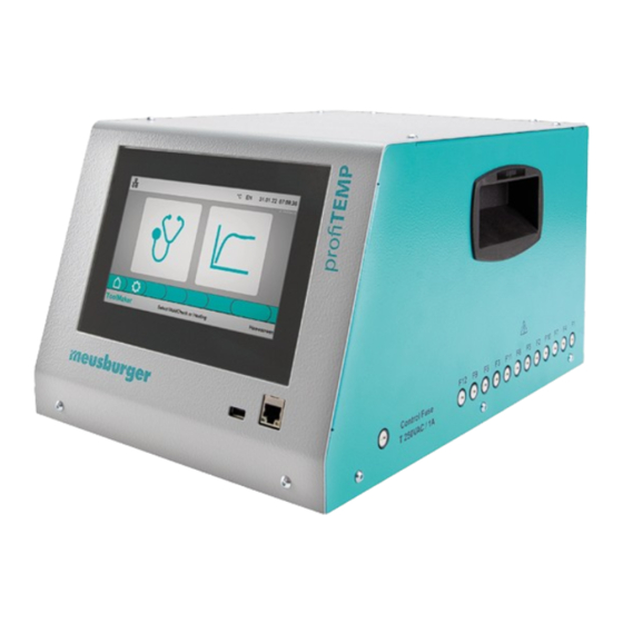
- Page 1 Hot runner diagnosis device profiTEMP TM Manual Download manual in additional languages at www.profiTEMP.de...
-
Page 3: Table Of Contents
CONTENT Introduction Read first, then start up Safety instructions Design and connections Front/side view Back view Mould connection Mains connection Operation Operating screen System settings MoldCheck operating mode (diagnosis) MoldCheck - step by step MoldCheck settings Heating mode Heating - step by step Heating settings Operating assistance Header... -
Page 5: Introduction
TM, manual, circuit diagrams READ FIRST, THEN START UP TRANSPORT The profiTEMP TM is supplied in shockproof packaging in a stable cardboard box. This ensures sufficient protection un- der normal circumstances. To avoid transport damage, the device must be transported STANDING UPRIGHT. UNPACKING Check the device for any transport damage. - Page 6 LIMITATION OF THE WARRANTY This manual has been carefully prepared and reviewed. Meusburger is not liable for any damage resulting from errors or mistakes in this manual. All data and facts given are not legally guaranteed. Meusburger reserves the right to make changes to this manual or the product described in it without prior notice if these serve to improve the product and/or technical progress.
-
Page 7: Safety Instructions
Chapter 2 - Safety instructions SAFETY INSTRUCTIONS All instructions must be read and followed completely. Everyone involved in the mounting, start-up, operation, maintenance and service of the device must be appropriately qualified to read and understand this Manual and must »... - Page 8 In all cases where the adjacent symbol can be seen on the device, it is absolutely necessary to follow the safety instruc- tions for the profiTEMP TM identified by the symbol/sign/label. In all cases, refer to this manual for advice.
-
Page 9: Design And Connections
Air vent MOULD CONNECTION The mould connection plugs on the device are designed in accordance with the Meusburger/PSG specification sheet. Each plug (24 contacts, size HAB B, surface-mounted housing with double locking latches) is provided for 6 zones. The profiTEMP TM has 12 zones so it has 2 mould connection plugs. -
Page 10: Mains Connection
Manual profiTEMP TM The connection diagram on the device must be compared with the connection diagram of the plug on the mould. Improper connection can destroy the controller, heater and thermal sensor. MAINS CONNECTION The device may only be operated with the mains voltage indicated on the label. The 32 A CEE power outlet intended for connection must be checked for sufficient permissible fuse protection. -
Page 11: Operation
Chapter 4 - Operation OPERATION After making all the necessary connections for the start-up of the device, set the main switch on the back of the device to the ON position. OPERATING SCREEN This diagnostic device is operated via the 7“ touch screen. For better readability of the screen, the front panel of the hou- sing is tilted. -
Page 12: System Settings
Manual profiTEMP TM SYSTEM SETTINGS Select the settings button in the menu bar. The following system settings, which are valid for the whole device, can be made: Maximum residual current defines from which measured residual current (heater insulation problems) heating outputs are switched off or a corresponding error is generated during diagnosis. -
Page 13: Moldcheck Operating Mode (Diagnosis)
Chapter 5 - MoldCheck operating mode (diagnosis) MOLDCHECK OPERATING MODE (DIAGNOSIS) MOLDCHECK - STEP BY STEP The MoldCheck checks the wiring and condition of all heating elements and thermal sensors (phase 1: electrical check). In addition, the correct allocation to the same zone is checked (phase 2: dynamic check). The inspection of every zone (its heating element and thermal sensor) is carried out continuously during operation, malfunctions are immediately signal- led in the zone as an alarm. - Page 14 Manual profiTEMP TM START MOLDCHECK Start the MoldCheck ... and confirm to start the query. The inverted start button indicates that a MoldCheck is running. The MoldCheck can be cancelled at any time by clicking the start button again. Once MoldCheck is started, the device does not require any input and MoldCheck can run unattended.
- Page 15 Chapter 5 - MoldCheck operating mode (diagnosis) Clicking on the row with the listed error leads to a zone error page describing the cause and detailed instructions for correcting the error. (ä 9.3 Symbols used). Clicking in the other area of the screen takes you back to the over- view page with the result of the MoldCheck.
-
Page 16: Moldcheck Settings
Manual profiTEMP TM MOLDCHECK SETTINGS Select the settings button in the menu bar. The following settings can be made: MoldCheck end temperature sets the maximum adjustable set point value for zones in control mode. MoldCheck rapid test If activated, then there is no check of the heater and sensor assignment. -
Page 17: Heating Mode
Chapter 6 - Heating mode HEATING MODE The heating operating mode is used to subject the hot runner to a function test or to preheat it for use in production (reduces set-up time). There are three modes to choose from (ä Control mode, ä Manual mode (user mode), ä Leading zone mode). - Page 18 Manual profiTEMP TM The symbols and data in the zone fields provide information about which mode the zone is in (ä 9.3 Symbols used). CONTROL MODE The zone is controlled to the adjusted set point value (here 125.5 °C). Zone 1 A Zone number 28.5 C...
- Page 19 Chapter 6 - Heating mode SET POINT VALUE INPUT Select the set point value button in the menu bar. Area A shows the zones that are in the control mode. Now select the zones whose set point values are to be changed. The zone is selected for set point input.
- Page 20 Manual profiTEMP TM Set the selected zones (here: zone 1) to manual mode (user mode) by clicking on the function button (area B) . Then enter the output value for the zones in the keyboard box (area C) (here: 10%) and confirm.
- Page 21 Chapter 6 - Heating mode The heating process can be followed in the screen mask. When all zones in the control mode reach the set temperature set point value, a 15 minute timer begins. The timer is displayed in the middle of the header. After the time is up, all the heaters are switched off.
-
Page 22: Heating Settings
Manual profiTEMP TM HEATING SETTINGS Select the settings button in the menu bar. The following settings can be made Upper relative limit value defines the tolerance band above the set point value. If the actual temperature value for a zone in control mode is above this value, an alarm is issued for this zone. -
Page 23: Operating Assistance
Chapter 7 - Operating assistance OPERATING ASSISTANCE HEADER NETWORK The status of the network interface can be recognised by the colour of the network symbol. The unit is not connected to any network. The unit is connected to a network, no data is being communicated. The unit is connected to a network and data is being communicated. -
Page 24: Footer
Manual profiTEMP TM Clicking on the time/date in the header displays the screen for setting the date and time. Click on the desired input field, make the entry and confirm. TIMER In the heating mode, a timer is displayed in the middle of the header (ä... -
Page 25: Conveniently Select And Deselect Zones
Chapter 7 - Operating assistance CONVENIENTLY SELECT AND DESELECT ZONES SELECT AND DESELECT ZONES INDIVIDUALLY By clicking on the zones, they can be selected or deselected. Click zone 2 Click zone 8 Zone 2 and Zone 8 are selected. BLOCK SELECTION A click on one zone followed by a double click on another zone selects or deselects all zones in between. -
Page 26: Service
Manual profiTEMP TM SERVICE It is essential to follow the instructions in the ä 2 Safety instructions . FUSE REPLACEMENT All fuses are accessible from the outside and are located on the right side wall when looking at the device from the front. -
Page 27: Appendix
The heating outputs of zones 1, 4, 7, 10 and 2, 5, 8, 11 and 3, 6, 9, 12 are each assigned to a phase L1/ L2/L3. MOULD CONNECTION Connector: Wieland WI 70.300.2440.0 Assignment: Meusburger Standard (001) CURRENT MEASURING Measuring range 0 to 16 A per power output Resolution 0.1 A (accuracy +/- 0.1A) -
Page 28: Declaration Of Conformity
All products have been developed and manufactured in compliance with applicable European standards and directives. A declaration of conformity can be requested from Meusburger . The manufacturer of the product, Meusburger, has a certified quality assurance system according to ISO 9001. SYMBOLS USED Icons are displayed in several screens to indicate the status of the zone or system. -
Page 29: Version History Documentation
Chapter 9 - Appendix Symbols Meaning Internal device error. Defect of the thyristor (power controller), the heating output is switched on perman- ently due to an error. MoldCheck The heating output of the zone is switched off. Heating The heating outputs of all zones belonging to the main phase failure in which the error was detec- ted are switched off. - Page 32 Rev. 1.00.02 Technical changes reserved Meusburger Georg GmbH & Co KG | Kesselstr. 42 | 6960 Wolfurt | Austria | T +43 5574 6706 office@meusburger.com | www.meusburger.com...
Need help?
Do you have a question about the profiTEMP TM and is the answer not in the manual?
Questions and answers