Table of Contents
Advertisement
Quick Links
Advertisement
Table of Contents

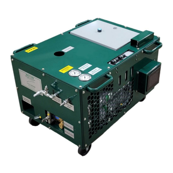
Summary of Contents for Mandus Group MG1100
- Page 1 Operation, Maintenance Manual and Replacement Parts List Portable Nitrogen Generator MG1100 July 1, 2022 2nd Edition, Rev. 0 Chg. 0 © Mandus Group Mandus Group LLC Phone: 1-888-922-8502 2408 4th Avenue E-Mail: customerservice@mandusgroup.com Rock Island, IL 61201 Website: www.mandusgroup.com...
- Page 2 MG1100 This information is believed to be accurate by the Mandus Group as of its date of publication, but the Mandus Group offers NO WARRANTY regarding the accuracy, or continuing accuracy, of the information set forth herein. The Mandus Group shall not be liable for inaccuracies in, or consequences resulting from, your use of this information.
-
Page 3: Table Of Contents
How to Use the Replacement Parts List..........................2 A.1.3 How to Use the Appendix ..............................2 Compressor Unit Technical Specifications ..................3 A.2.1 MG1100 .................................... 3 A.2.2 Compressor Block Technical Specifications ........................3 A.2.3 Compressor Drive Technical Specifications ........................3 VOLUME B: ------------------------------------------------------------ OBJECTIVE Feed Air Requirements ........................ - Page 4 MG1100 D.2.2 Every 125 Operating Hours ............................12 D.2.3 Every 500 Operating Hours or Annually ........................12 D.2.4 Every 2000 Operating Hours or Biennially ........................12 D.2.5 After Repair Work ................................12 D.2.6 After Storage and Preservation ............................13 VOLUME E ------------------------------- SYSTEM MAINTENANCE CHART Scheduled Maintenance ........................
- Page 5 MG1100 I.1.4.1 Description ................................... 23 I.1.4.2 Checking the Drive Belt ............................... 23 I.1.4.3 V-belt Tension Adjustment............................24 I.1.5 Electric Motor Maintenance ............................. 25 I.1.6 Replacement Parts ................................25 VOLUME J: --------------------------------------------------------------- APPENDIX Safety ..............................26 J.1.1 General Safety Precautions .............................. 26 J.1.2...
- Page 6 MG1100 LIST OF FIGURES Title Page Figure B-3 Electrical Controls ..............................6 Figure C-1 Manual Drains ............................... 8 Figure E-1 Low Pressure Filter ............................... 14 Figure E-2 Low Pressure Filter Assembly ..........................15 Figure F-1 Oil Dipstick Markings ............................17 Figure F-2 Oil Drain Port.
-
Page 8: Volume A
If your unit is equipped with nonstandard accessories and/or options, supplemental information is normally included in other documentation; i.e. OEM Manuals or additional Mandus Group Manuals. Important instructions concerning the endangerment of personnel, technical safety or operator safety will... -
Page 9: How To Use The Replacement Parts List
Valve WARNING The use of repair parts other than those included in the Mandus Group Replacement Parts Lists may create unsafe conditions over which the Mandus Group has no control. Such unsafe conditions can lead to accidents that may be life-threatening, cause substantial bodily injury, and/or result in damage to the equipment. -
Page 10: Compressor Unit Technical Specifications
MG1100 Compressor Unit Technical Specifications All technical specifications are subject to change without prior notice. A.2.1 MG1100 Medium........................Nitrogen Final Product Purity ................... ≤96.5% to 99.5% Intake Pressure................100 - 150 psig (6.9 - 10 bar) Feed Air Quantity Required ..............6 SCFM (170 l/min) Feed Air Temperature Range ............ -
Page 11: Volume B
MG1100 VOLUME B: OBJECTIVE The purpose of the MG1100 is to take regulated, filtered, clean, dry shop air and separate the oxygen out of the air stream and save the nitrogen. B.1 Feed Air Requirements The inlet, or feed air, must meet the following criteria: •... -
Page 12: Unpacking, Handling And Installation
MG1100 such as nitrogen and other inert gases, continue through the membrane and exit the membrane outlet manifold. After leaving the membrane outlet manifold the mainstream flows to the regulator. The pressure in the system is controlled using this regulator. -
Page 13: Installation
MG1100 B.3.4 Installation B.3.4.1 Location It is recommended that the nitrogen generation unit be located indoors in an ambient temperature range between 40 °F and 115 °F (5 °C and 45 °C). Should the application require that the unit be located outdoors, a shelter must be provided to protect the unit from direct sun light, rain, wind and ambient temperatures that fall outside of the temperature range listed above. -
Page 14: Operation And Maintenance Precautions For Compressed Gas Systems
MG1100 B.3.6.1 Operation and Maintenance Precautions for Compressed Gas Systems 1. Always handle compressed gas with care. Pressurized gas, particularly when directed at a person’s body or face, can cause serious injuries. 2. Do not use the unit discharge for breathing purposes. High purity nitrogen gas is toxic and severe injury or death can result. -
Page 15: Before Starting
The HMI should then load into the main screen. Once on the main screen select “Start” to begin operating. 3. The MG1100 will now warm-up. Until the nitrogen gas reaches the purity level set on the oxygen monitor, the gas will be vented to the atmosphere. Thirty (30) seconds after reaching the required purity (96.5%), the gas will be supplied to the outlet fitting. -
Page 16: Other Hmi Screens
The Cool Down period will be marked with a blue pop up that says “Cool Down.” The Cool Down period is to allow for both the compressor and motor to cool down. Make sure to leave the MG1100 powered on during this, because the cool down timer pauses while the unit is powered down. There is an override option “Press for Override”... -
Page 17: Maintenance Alerts
MG1100 Purification Warning Replace purification chamber and inter- mediate separator. Purification Alarm Contact Mandus Group. C.7 Maintenance Alerts C.7.1 Filter Change Required The two coalescing filters incorporate differential pressure indicators which are used to monitor the condition of the filter elements. When the filters become clogged, the filter indicator of one filter registers in the red field, replace all three filter elements as a set, never just a single element. -
Page 18: Maintenance Record
MG1100 VOLUME D: HIGH PRESSURE MAINTENANCE SCHEDULE WARNING Always shut down and decompress the complete system prior to carrying out any work on the compressor Never repair pressure lines by soldering or welding. CAUTION Change the purifier cartridge according to Purification chapter. The used purifier cartridge must be disposed of according to local regulations. -
Page 19: Every 500 Operating Hours Or Annually
MG1100 D.2.3 Every 500 Operating Hours or Annually Date Signature Change Purification Cartridge. [see G.1.2.1 on page 21] Change Inlet Filter Elements. [see E.2 on page 14] D.2.4 Every 2000 Operating Hours or Biennially Date Signature Change synthetic based compressor oil. -
Page 20: After Storage And Preservation
MG1100 D.2.6 After Storage and Preservation Date Signature Check tension and condition of V-belt. [see I.1.4.2 on page 24] Check zero pressure position on the final pressure gauge when de-pressurized. [see I.1.2 on page 23] Page 13 2nd Edition, Rev. 0 Chg. 0... -
Page 21: Scheduled Maintenance
2. Auto Drain a.See I.1.6 on page 26 for part numbers Disconnect the MG1100 as well as open the manual drains before performing any maintenance on this unit. This is to ensure the unit is depressurized. The low-pressure filters are pictured below:... -
Page 22: Figure E-2 Low Pressure Filter Assembly
MG1100 Figure E-2 Low Pressure Filter Assembly Direction of Flow 1. There are three low-pressure filters and they are arranged from inlet to outlet, 1 micron filter, 0.01 micron filter, and adsorber filter. In Figure E-2 the coalescing filters are located on the left, the, activated carbon filter is on the right. - Page 23 MG1100 NOTICE Make certain that the O-ring inside the top of the bowl is lightly lubricated with O-ring lubricant and that the O-ring is in place. 7. Reassemble filter bowl to filter head. July 1, 2022 Page 16...
-
Page 24: Lubrication
Type of Oil NOTICE The part number for the oil delivered in all MG1100 compressor units is 1CØ351. 1CØ351 is 1 Qt. Make sure to order a qty of at least 2 for a single system oil change. Due to the thermal load on the compressor, only high quality oil should be used. It is recommended that you restrict oil to 1CØ351 which has a proven record of success and is specified for this compressor. -
Page 25: Oil Change Schedule
MG1100 F.1.3 Oil Change Schedule The oil must be changed every 2,000 operating hours or every two years whichever is reached first. F.1.4 Oil Change Procedures 1. Run the compressor until it reaches normal operating temperature, then shut it off. -
Page 26: Electric Motor
MG1100 TROUBLE CAUSE REMEDY Pipe coupling leaking. Retighten couplings. Intermediate pressure safety Intermediate pressure too high Check and replace inlet or valve blows. because of defective inlet or pressure valve. pressure valve of the following stage. Safety valve leaking. Replace safety valve. -
Page 27: Description
MG1100 VOLUME G: PURIFICATION SYSTEM G.1 Purification Chamber G.1.1 Description The P0 Purification System consists of a separator and a cartridge chamber. In the separator surrounding the cartridge chamber, liquid oil and water particles are separated from the compressed air by a pipe nozzle. -
Page 28: Maintenance
MG1100 Figure G-2 Purification Chamber Cross Section Cartridge Removal 1. Inlet 7. Adjustment Knob 2. Cartridge 8. Separator Chamber 3. Jet Pipe 9. Outlet 4. Housing 10. Pressure Maintaining Valve 5. Plug 11. Bottom 6. Final Pressure Safety Valve G.1.2 Maintenance G.1.2.1... -
Page 29: Chamber Replacement Interval
MG1100 G.1.2.2 Chamber Replacement Interval See Systems Fault Chart C.6 WARNING The Purification Chamber is subject to dynamic loading. It is designed for a certain number of load cycles. A load cycle equates to an abrupt pressure loss caused by draining the condensate. -
Page 30: Electrical Enclosure
MG1100 VOLUME H: ELECTRICAL H.1 Electrical Enclosure The electrical enclosure contains the PLC, starter, fuses, relays, and connectors, which monitor and control the nitrogen generating unit. The front of the electrical enclosure houses an overload rest button. Figure H-1 Electrical Controls 1. -
Page 31: Safety Valves
MG1100 VOLUME I: MISCELLANEOUS Safety Valves I.1.1 Description Both stages of compression are protected by safety valves. The 1st stage and final safety valves are adjusted to the correct pressure and sealed at the factory. The final stage safety valve is mounted on top of the purification chamber and is adjusted to the operating pressure of the unit. -
Page 32: V-Belt Tension Adjustment
MG1100 4. Check for damage or wear every 125 operating hours. Figure I-2 Checking V-belt Tension Figure I-3 V-belt Pulley Alignment Approximate Deflection 3/8 " (10mm) I.1.4.3 V-belt Tension Adjustment 1. Slightly loosen, but don’t remove the 4 bolts (1) [2 on each side of motor] holding the electric motor onto the base plate. -
Page 33: Electric Motor Maintenance
MG1100 2. Tighten the electric motor mounting bolts. 3. Operate the unit for approximately five (5) minutes. Stop the prime mover, check V-belt tension and readjust if necessary. 4. After the V-belt tension is correct and the prime mover mounting bolts are tight, check to verify that both pulleys are aligned. -
Page 34: Safety
MG1100 VOLUME J: APPENDIX J.1 Safety J.1.1 General Safety Precautions • Read the operating manual before installing or operating this compressor unit. Follow appropriate handling, operation and maintenance procedures from the very beginning. The maintenance schedule contains measures required to keep this compressor unit in good condition. Maintenance is simple, but must be executed regularly to achieve safe operation, maximum efficiency and long service life. - Page 35 • The use of repair parts other than those listed in this manual may create unsafe conditions over which the Mandus Group has no control. Such unsafe conditions can lead to accidents that may be life- threatening, cause substantial bodily injury, and/or result in damage to the equipment. Therefore, the...
-
Page 36: Safety Warning Labels
MG1100 J.1.2 Safety Warning Labels Notes, labels and warning signs are displayed on the compressor unit according to model, application or equipment and may include any of the following. HOT SURFACES DO NOT TOUCH! Danger of burning if cylinders, cylinder heads, or pressure lines of individual compressor stages are touched. -
Page 37: Approved Lubricants Chart
MG1100 J.2 Approved Lubricants Chart Unless otherwise specified in text, use the lubricants in Table J-1. Table J-1: Lubricant Chart Usage Lubricants Parker Super “O” Lube O-rings, rubber and plastic parts; filter housing threads, sealing rings (1CØLUBE) Bolts, nuts, studs, valve parts, copper gaskets and...
Need help?
Do you have a question about the MG1100 and is the answer not in the manual?
Questions and answers