
Summary of Contents for Amensolar POWER BOX A5120x2
- Page 1 Battery Module User Manual Product Name: 2U Wall Mounted-Battery Module POWER BOX A5120x2 (Certificate Model: YNJB16S100KX-L-2PD) Version: P1.0 No. 1 Page...
-
Page 2: Table Of Contents
This manual describes the instructions for using the 2U Wall Mount - Battery Module (POWER BOX A5120x2). Please read this manual before installing the battery and follow the instructions carefully during installation. In case of any confusion, contact the manufacturer immediately for advice and clarification. -
Page 3: Chapter 1 Product Introduction
Chapter 1 Product Introduction The 2U Wall Mounted - Battery Module (POWER BOX A5120x2) is one of the new energy storage products that can be used to support reliable power for a variety of devices and systems. It is especially suitable for application scenarios with high power, limited installation space, restricted load bearing and long cycle life. - Page 4 Supports two levels of overcurrent protection; Supports output short circuit protection; Supports reverse polarity protection; Support for data storage; Multiple automatic fault detection (sampling, MOS, battery failure) 1.3. Specification No. 4 Page...
- Page 5 Battery Module Dimension Drawing Mounting Bracket Dimension Drawing No. 5 Page...
- Page 6 Product Model POWER BOX A5120X2 Rated Battery Voltage 51.2V Operating Voltage Range 44.8V to 57.6V Float charging voltage support 55V±1V battery capacity 200Ah battery level 10240Wh internal resistance ≤50mΩ Rated discharge current/Maximum 100A/200A allowable discharge current Rated charging current/maximum 100A/200A allowable charging current Charging 0℃~+56℃...
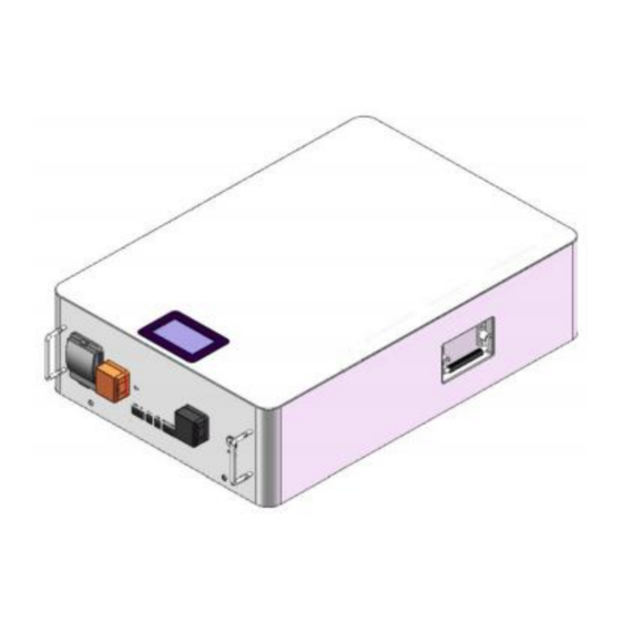
- Page 7 Breaker Circuit breaker: load isolation. ground connection Ground connection: equipment grounding. monitor Display: Displays the parameters of the battery module. power switch Power switch: turns on the battery pack status. Power terminals (B+/B-) Power terminals: Use two pairs of terminals with the same function using cold press terminals RNB22-8, one connected to the unit and the other connected in parallel to other battery modules for capacity increase.
- Page 8 (2) Battery parameter acquisition page After clicking BMS, you will enter the "Battery Parameter Acquisition" page, as shown in the following figure: To go back press the blank space at the edge. No. 8 Page...
- Page 9 RS485/CAN interface RS485/CAN communication interface: (RJ45 port) Communication according to RS485/CAN protocol. RS485 - using 8P8C vertical RJ45 socket CAN - using 8P8C vertical RJ45 socket RS485 RJ45 Pin Description of RJ45 Pin Description definitions of definitions 9, 16 RS485-B1 1, 2, 3, 6, 8 10, 15 RS485-A1...
-
Page 10: Chapter 2 Battery Module Safe Handling Guidelines
Chapter 2 Battery Module Safe Handling Guidelines 2.1. System Topology 2.2. markings 2.3. tools To install the battery pack, you may need these tools below: name (of a thing) Screwdrivers (one, Phillips) multimeter torque wrench clamp meter tweezers insulating tape tweezers thermometers wiresnipers... -
Page 11: Chapter 3 Product Installation Instructions
M5*10mm carabiner pendant pan head screw M6*20 Wall mounted racks 400*740mm User's Manual POWER BOX A5120X2 Packing List POWER BOX A5120X2 warranty card POWER BOX A5120X2 Chapter 3 Product Installation Instructions 3.1. Connection Instructions NOTE: For safe operation and regulatory compliance, a separate DC overcurrent protector or disconnect is required for battery installation. - Page 12 ring terminal battery Cable Size sizes capacity Cable mm D (mm) L(mm) 200Ah 2AWG 33.5 3.2. Installation conditions Make sure that the installation location meets the following conditions: The area is completely waterproof. The flooring is flat. No flammable or explosive materials. ...
- Page 13 Put M8*60 expansion screws into the drilled holes. Place the wall-mounted rack on the M8*60 expansion screws and fix it. Simply attach the snap-on pendant on the wall-mounted battery module to the slot with the snap-on clip. No. 13 Page...
- Page 14 B. Parallel installation 1. Set 6 points on the wall and use φ10*90 impact drill to drill holes. 2. Put M8*60 expansion screws into the drilled holes. 3. Place the wall-mounted rack on the M8*60 expansion screws and fix it. 4.
- Page 15 No. 15 Page...
-
Page 16: Chapter 4 Safety Precautions
NOTE: If all the displays are lit, this means the battery system is good and working properly. Chapter 4 Safety Precautions warnings 4.1. Precautions before installation 1) After opening the box, please check the product and packing list first, if the product is damaged or missing parts, please contact your local retailer;... -
Page 17: Chapter 5 Troubleshooting
Chapter 5 Troubleshooting 5.1. Troubleshooting Steps 1) Can the battery be turned on; 2) If the battery is on, check to see if the red light is off, blinking or on; 3) If the red light is off, check that the battery can be charged/discharged. 5.2. - Page 18 Ingestion: Induce vomiting and seek medical attention. 6.2. fire (that burns buildings etc) Do not use water! Use only a dry powder fire extinguisher; if possible, move the battery pack to a safe area before it catches fire. 6.3. soak If the battery pack gets wet or is submerged in water, do not let anyone touch it and then contact the manufacturer or an authorized dealer for technical support.
Need help?
Do you have a question about the POWER BOX A5120x2 and is the answer not in the manual?
Questions and answers