Table of Contents
Advertisement
Advertisement
Table of Contents

Related Manuals for Energy Recovery 8500 Series

Summary of Contents for Energy Recovery 8500 Series
- Page 1 INSTALLATION, OPERATION, & MAINTENANCE MANUAL Series 8500, 2400, 1200 PX Booster Pumps Energy Recovery Inc. 1717 Doolittle Drive, San Leandro, CA 94577 Tel: 1 510 483-7370 / Fax: 1 510 483-7371 www.energyrecovery.com Energy Recovery, Inc. ERI Document Number 80020-01-5...
-
Page 2: Table Of Contents
NSTALL THE ECHANICAL 7.4 D ISASSEMBLY OF 7.5 A SSEMBLY OF 7.6 M OTOR EARING ERVICE 8.0 TROUBLE SHOOTING 9.0 ERI FIELD COMMISSIONING 10.0 WARRANTY AND LIABILITY 11.0 REVISION LOG 12.0 DRAWINGS AND DATA Energy Recovery, Inc. ERI Document Number 80020-01-5... -
Page 3: Introduction
08:00 to 17:00 Pacific Standard Time. Field service and system commissioning assistance are available. Further information about PX Booster Pumps or other Energy Recovery, Inc. products or service can be found by contacting Energy Recovery, Inc. at: Energy Recovery Inc. -
Page 4: Safety, Arrival And Inspection
Table 6-1 can result in damage to the PX Booster Pump. Energy Recovery, Inc. declares that ERI PX Booster Pump product lines comply with the essential requirements for CE certification. A CE label is located on the booster pump nameplate. -
Page 5: Principle Of Operation
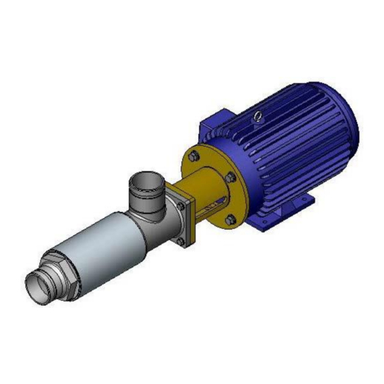
The PX Booster Pump is a horizontal multistage centrifugal pump driven by a Totally Enclosed Fan Cooled (TEFC) motor. The PX Booster Pump boosts the pressure in the high pressure portion of an SWRO system to make up the small pressure losses that occur Energy Recovery, Inc. ERI Document Number 80020-01-5... - Page 6 In an SWRO system equipped with PX technology, the main pump is sized to equal the SWRO permeate flow plus a small amount of bearing lubrication flow, not the full SWRO feed flow. Energy Recovery, Inc. ERI Document Number 80020-01-5...
-
Page 7: Installation
SWRO system equipped with PX technology, the main pump will provide 41% of the energy, the booster will provide 2% and the PX unit(s) will provide the remaining 57%. Since the PX energy recovery device uses no external power, the total power savings is 57% compared to a system with no energy recovery. - Page 8 This can cause failure of mechanical seal, shaft and motor Never stand and/or sit on pump wet end. CAUTION Never lift or handle pump wet end while transporting it. All lifting should be done around the motor. Energy Recovery, Inc. ERI Document Number 80020-01-5...
-
Page 9: Operation
Failure to observe these conditions and precautions can result in violation of the warranty, damage to the equipment, and/or harm to personnel. 6.1.1 System Performance Specifications Table 6-1 provides a summary of system performance specifications. See Section 12.0 for flow and pressure curves. Energy Recovery, Inc. ERI Document Number 80020-01-5... -
Page 10: Precautions And
Pumps are listed in Table 6-1. PX Booster Pumps are not designed to operate outside of these ranges. 6.1.4 Physical Characteristics See Section 13.0 for weights and dimensions. Connections dimensions and requirements are provided in Table 6-2. Energy Recovery, Inc. ERI Document Number 80020-01-5... -
Page 11: Spare Parts
3. Supply feed water to the SWRO system and the PX unit’s low-pressure inlet. 4. Typically, the SWRO system and PX unit’s high-pressure loop must be filled with feed water through high pressure pump because PX unit’s high pressure loop and low pressure loop are Energy Recovery, Inc. ERI Document Number 80020-01-5... - Page 12 A sample operating-log has been provided in Section 8.0 of this manual and must be submitted by fax or e-mail to Energy Recovery, Inc. in San Leandro, California upon completion of the startup and flow balancing routines. ERI requests submittal of this form with the initial startup data within 24 hours of startup.
-
Page 13: Maintenance Instructions
SERIES 8500-2400 PX BOOSTER PUMPS A sample operating-log has been provided at the end of Section 8.0 and must be submitted by fax or e-mail to Energy Recovery, Inc. NOTE upon completion of the startup and balancing routines. The data must be recorded daily and maintained during the life of the warranty in order to support any claims. -
Page 14: Echanical Eal
Figure 7-1 - Section View of Shaft and Seal Components Seal Inlet Motor Coupling Bell Pump Plate Housing Shaft Housing Shaft Window to check Compression shafts in Retaining contact Ring Spacer 10122-01 Primary Stationary Jack Shim Seal Seal Screw Spacer(s) O-Ring 10055-01 Energy Recovery, Inc. ERI Document Number 80020-01-5... - Page 15 6. Remove the four bolts that hold the inlet housing to the bell housing with a 9/16” wrench as shown in Figure 7-4. Figure 7-3 - Loosen Coupling Screws Figure 7-2 - Pump Oriented Vertically Bell Housing Access Slot Coupling Screws (4x2) Energy Recovery, Inc. ERI Document Number 80020-01-5...
- Page 16 Figure 7-8. Be careful not to strip the set screws. If a particular set screw is very tight, it may be necessary to rotate the shaft and loosen a different set screw first. Energy Recovery, Inc. ERI Document Number 80020-01-5...
- Page 17 Keep the shafts and coupling clean and free of dirt, rust and foreign CAUTION matter. Use plenty of anti-seize upon reassembly to ensure easy disassembly the next time. Figure 7-9 - Remove Bell Housing Energy Recovery, Inc. ERI Document Number 80020-01-5...
- Page 18 See Figure 7-12 and 7-13 for the correct sequence. Tighten the three set screws to 7 inch-pounds (in-lbs) / 0.79 Newton-meters (N-m) torque using a 3/32-inch hex wrench. Energy Recovery, Inc. ERI Document Number 80020-01-5...
- Page 19 Figure 7-14 - Insert Anti-Rotation Pin Figure 7-15 - Stationary Seal, Line up Pin with Groove Groove 7. Slide the seal plate onto the shaft as shown in Figure 7-16. Energy Recovery, Inc. ERI Document Number 80020-01-5...
- Page 20 9. Assemble the seal compression tool components using a flexible coupling as shown in Figure 7-18. Alternately, compress seal manually as shown in Figure 7-19. Figure 7-18 – Assemble and Install Seal Compression Tool Components Energy Recovery, Inc. ERI Document Number 80020-01-5...
- Page 21 Figure 7-20 - Check Seal Compression Circular Window to Check Compression Under Correct Over Compressed Compression Compressed Figure 7-21 – Add or Remove Fender Washer(s) or Shim Spacer(s) to Change Seal Compression Energy Recovery, Inc. ERI Document Number 80020-01-5...
- Page 22 Inlet Housing Bell Housing Access Slot Coupling Screws (4x2) 16. Tighten both halves of the coupling evenly making sure that the gap between the two halves is equal as shown in Figure 7-24. Energy Recovery, Inc. ERI Document Number 80020-01-5...
- Page 23 (4) bolts 2 revolutions. Then torque the four (4) bolts between the inlet housing and the bell housing to 12 ft-lbs (16 N-m) as shown in Figure 7-25. Energy Recovery, Inc. ERI Document Number 80020-01-5...
- Page 24 3. Loosen the pump head with a pipe wrench on the outlet nozzle as shown in Figure 7-26. 4. Loosen the shell with a strap wrench as shown in Figure 7-27. Figure 7-26 – Loosen Outlet Nozzle Figure 7-27 – Loosen Shell Energy Recovery, Inc. ERI Document Number 80020-01-5...
- Page 25 Figure 7-29 - Install Coupling and Bell Housing Drainage Hole 4. Install the seal and seal plate onto the shaft as shown in Figure 7-30. Figure 7-30 – Install seal and seal plate onto shaft Energy Recovery, Inc. ERI Document Number 80020-01-5...
- Page 26 8. When the seal compression is correct, torque the coupling screws according to the requirements listed in Table 7-4 above. Make sure the gap between the two halves of the coupling is even on both sides as shown in Figure 7-34. The coupling must be tightened Energy Recovery, Inc. ERI Document Number 80020-01-5...
- Page 27 Remove the impeller and add or subtract spacers onto the shaft as necessary to adjust the gap. Figure 7-35 - Install First Diffuser Plate First Spacer Washers First Diffuser Plate Mechanical Stop Inlet Nozzle Seat Energy Recovery, Inc. ERI Document Number 80020-01-5...
- Page 28 The diffuser bowl, spacer washer (optional), bearing journal, thrust washer, impeller and diffuser plate make up a complete stage assembly as shown in Figure 7-38. Stack in the order shown in Figure 7-38 or 7-39 until the pump is complete. Energy Recovery, Inc. ERI Document Number 80020-01-5...
- Page 29 Figure 7-39 - Complete Stage Assembly for 2400-Series Pumps Diffuser Bowl Bowl Sleeve Spacer Washer(s) (optional) Bearing journal Thrust washer Impeller 11. Install the last diffuser plate. Install the snap ring as shown in Figure 7-40 or 7-41. Energy Recovery, Inc. ERI Document Number 80020-01-5...
- Page 30 Figure 7-44 below. Insufficient torque will result in the bowls breaking free, spinning and pump failure. Figure 7-42 - Install Shell and Outlet Nozzle Energy Recovery, Inc. ERI Document Number 80020-01-5...
- Page 31 The motor bearings in ERI motors will provide a long service life if properly and regularly lubricated. The motor manual included in Section 12.0 provides guidance for proper motor maintenance. In case of bearing failure, ERI supplies the replacement bearings listed in Table 7- Energy Recovery, Inc. ERI Document Number 80020-01-5...
-
Page 32: Remove The Old
6. Remove the fan cover from the motor. 7. Remove fan snap ring. 8. Remove the fan. 9. Remove the rubber slingers (x2). 10. Remove the bearing lubrication covers (x2). See Figure 7-45. Energy Recovery, Inc. ERI Document Number 80020-01-5... - Page 33 Figure 7-47 – Remove Rotor and Shaft Assembly Wave Spring (not visible) Motor Body Thrust Retainer Rotor Retainer Back Bell Bearing Plate Plate 13. Remove the thrust bearing retaining ring. See Figure 7-48. Energy Recovery, Inc. ERI Document Number 80020-01-5...
- Page 34 17. Install back bell onto rotor and shaft assembly. It maybe necessary to tap back bell with a rubber mallet to ease the assembly process. 18. Ensure wave spring is inside counterbore in back motor bell. 19. Slide bearing lubrication cover onto shaft. Energy Recovery, Inc. ERI Document Number 80020-01-5...
-
Page 35: Trouble Shooting
The best troubleshooting tool is the knowledge of the plant gained through experience. Any condition not covered in this section may be resolved by contacting Energy Recovery, Inc.’s Service Department. Preliminary procedures: 1. - Page 36 Make sure that the switch is not loose on the shaft. Inspect contacts and connections on the stationary switch. Replace switch if the contacts are burned or pitted. Energy Recovery, Inc. ERI Document Number 80020-01-5...
- Page 37 Ambient temperature too high. Verify that the motor is getting enough air for proper cooling. Most motors are designed to run in an ambient temperature of less than 40°C. (Note: A properly operating motor may be hot to the touch.) Energy Recovery, Inc. ERI Document Number 80020-01-5...
- Page 38 I. Excessive noise Excessive flow rate. Lower flow rate or apply backpressure to pump. Insufficient feed water. Check feed pressure and inspect wet end assembly. Motor bearing failure. Check motor bearings and/or replace motor. Energy Recovery, Inc. ERI Document Number 80020-01-5...
- Page 39 SERIES 8500-2400 PX BOOSTER PUMPS ENERGY RECOVERY, INC. SAMPLE OPERATING LOG NOTE: Daily data must be collected and maintained to support any warranty claims. Initial data must be submitted within 24 hours of startup. Fax: +1 510 483 7371 Attn: Warranty Administration Department...
-
Page 40: Eri Field Commissioning
Should a problem develop with any ERI product, our Technical Services group is prepared to handle customers’ concerns whether the location is domestic or overseas. Service rates are available upon request. Energy Recovery Inc. 1717 Doolittle Drive, San Leandro, CA 94577 Tel: 1 510 483-7370 / Fax: 1 510 483-7371 www.energyrecovery.com... -
Page 41: Warranty And Liability
SERIES 8500-2400 PX BOOSTER PUMPS 10.0 WARRANTY AND LIABILITY Energy Recovery, Inc. (ERI) warrants that its PX Booster Pump(s) will not fail or malfunction as a result of defects in materials, workmanship, or design for a period of twelve (12) months from date of shipment. - Page 42 4. All piping shall be cleaned and flushed with water so that all construction debris is removed from the system before installing or operating the PX Booster Pump. 5. In preparation for extended plant shutdowns, PX Booster Pumps must be flushed with permeate and a biocide. Energy Recovery, Inc. ERI Document Number 80020-01-5...
-
Page 43: Revision Log
CE Certification manual additions. 6/17/20 12.0 DRAWINGS AND DATA PX Booster Pump Assembly Drawings, Overall Dimensions and Labeling Diagrams, Shipping Configuration Drawings PX Booster Pump Characteristic (Pump) Curves Energy Recovery, Inc. ERI Document Number 80020-01-5... - Page 44 SERIES 8500-2400 PX BOOSTER PUMPS 3. Glycerin SDS Energy Recovery, Inc. ERI Document Number 80020-01-5...
- Page 45 SERIES 8500-2400 PX BOOSTER PUMPS Energy Recovery, Inc. ERI Document Number 80020-01-5...
- Page 46 SERIES 8500-2400 PX BOOSTER PUMPS Energy Recovery, Inc. ERI Document Number 80020-01-5...
- Page 47 SERIES 8500-2400 PX BOOSTER PUMPS Energy Recovery, Inc. ERI Document Number 80020-01-5...
- Page 48 SERIES 8500-2400 PX BOOSTER PUMPS Energy Recovery, Inc. ERI Document Number 80020-01-5...
- Page 49 SERIES 8500-2400 PX BOOSTER PUMPS Energy Recovery, Inc. ERI Document Number 80020-01-5...
Need help?
Do you have a question about the 8500 Series and is the answer not in the manual?
Questions and answers
Do you have available following items: - SEAL KIT, HP-2403 8EA - HP-2203-REBUILT KIT 2EA - PUMP, BOOSTER ASSY. NO MOTOR, FR256TCM, 20HP,2P,690V,60HZ 4EA