Advertisement
Quick Links
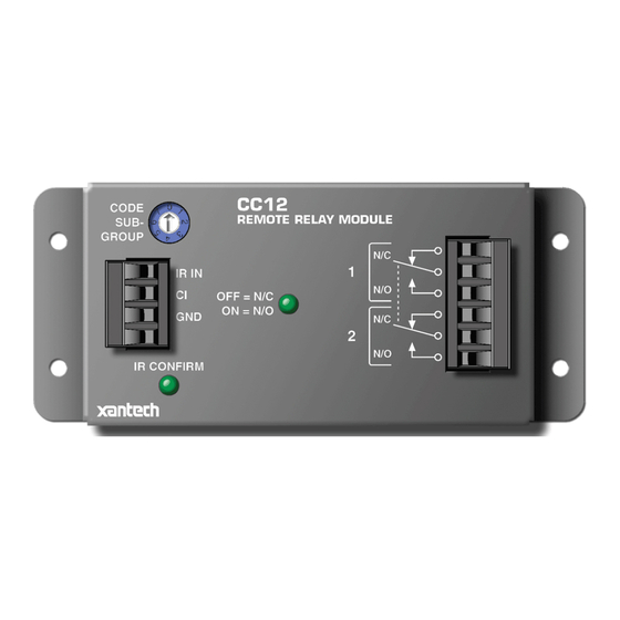
The CC12, Fig. 1, is an IR Remote Controlled Double Pole Double Throw Relay Module. It provides dry
contact closures to satisfy a variety of uses, such as activation of screen drops, projector lifts, etc. The
switching is accomplished by way of infrared commands originating from a Xantech RC68+ Programmer
(or RC68 Programmer). It can also be switched by a DC voltage applied between the CI (control input) and
GND terminals. The RC68+ commands are "taught" to learning devices and passed to the IR IN, and GND
input terminals of the CC12 signal input terminals via Xantech IR Receivers, Keypads and Connecting
Blocks.
FEATURES AND SPECIFICATIONS
• One 6-terminal plug-in connector to make connection to the internal DPDT relay.
• 5 Amp/30V DC relay contact rating.
• 4-terminal IR input (S = IR Signal, CI = Control Input, G = Gnd, V = +12V) for connection of Xantech IR
Receivers, Smart Pads, Connecting Blocks and other devices.
• All plug-in connectors accept wire sizes from 24 to 12 gauge.
• IR CONFIRM LED goes on only when an RC68+ (or RC68) IR command signal activates unit.
• LED turns ON when N/O (normally open) contacts are closed and goes OFF when N/C (normally closed)
contacts are closed.
• Four RC68+ IR commands permit Pair, Toggle, and Momentary operation of the switching relay.
• IR activated ON condition (N/O contacts closed) goes OFF if power is interrupted.
• +3V to +30V DC 1 mA applied to CI terminal will switch unit, instead of IR, if desired.
• Factory preset Group Code number: 50.
• CODE SUB-GROUP switch allows a choice of 8 different groups of the four RC68++ commands that
operate the CC12. This prevents mutual interaction in common IR systems when using more than one
CC12 Also, internal E
combinations if the system uses more than eight CC12's or in combination with SR21's.
• Power: +12V DC @ 50 mA. Use the 781RG Power Supply for each CC12. If IR receivers or keypads
are used on the same 12V line, use the 782-00 Power Supply.
• Flanges, plus supplied screws, permits easy mounting to flat surfaces.
• Dimensions: 5-1/4" x 2-3/8" x 1-7/8".
INSTALLATION INSTRUCTIONS
CC12
REMOTE RELAY MODULE
CC12
CODE
REMOTE RELAY MODULE
SUB-
GROUP
IR IN
CI
OFF = N/C
ON = N/O
GND
+12VDC
IR CONFIRM
Fig. 1 The CC12
2
PROM can be set to different code groups, allowing up to 240 different IR code
N/C
1
N/O
N/C
2
N/O
1
Advertisement

Related Manuals for Xantech CC12

Summary of Contents for Xantech CC12
- Page 1 • One 6-terminal plug-in connector to make connection to the internal DPDT relay. • 5 Amp/30V DC relay contact rating. • 4-terminal IR input (S = IR Signal, CI = Control Input, G = Gnd, V = +12V) for connection of Xantech IR Receivers, Smart Pads, Connecting Blocks and other devices.
- Page 2 NOTE: When shipped from the factory, the CC12 is set to code group number 50. Be sure to set the RC68+ to the same number! It may be necessary to change the CC12 to a different code group if it is used in a common IR bus controlled system with many CC12'S, SR21's, etc., to avoid mutual interaction.
- Page 3 RC68+ (or RC68) Programmer. Refer to Fig. 2. • A 780-80 "J" box IR Receiver is shown for IR control of the system. Any of the other Xantech IR Receivers or keypads could also be used, depending on your system and aesthetic requirements. The STATUS LED indicator in the 780-80 can be driven by a +12V System Status (ON/OFF) voltage, such as from an adapter plugged into the Switched AC outlet on the system A/V receiver.
- Page 4 (up to 5 Amps) with a low current DC control signal. • In Fig. 6, the STATUS (or CO output) of a ZPR68 (+12V) drives the CI (control input) of a CC12 when the zone is turned ON &...
Need help?
Do you have a question about the CC12 and is the answer not in the manual?
Questions and answers