
Related Manuals for LS Control VentilationAlarm EP2


Summary of Contents for LS Control VentilationAlarm EP2
- Page 1 User Manual VentilationAlarm EP2 949-208647 VentAlarm-EP2_24V-230V_ES1162 Manual Rev.1.2 06/2023 RJ/DF/UP...
-
Page 2: Table Of Contents
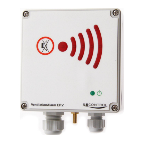
VentilationAlarm EP2 Highlights VentilationAlarm EP2 is a universal alarm with sound and light signal. It is used to monitor pressure, temperature or a 0-10V signal, where alarm is required when a value / setpoint is exceeded. External equipment such as external alarm lamp or rotating light can be connected. Also the VentilationAlarm EP2 can be used with ModBus for monitoring. -
Page 3: Safety Instructions
Safety Instructions Read the entire manual before installation and use of VentilationAlarm EP2. If the instructions in this manual are not followed it may cause damage to the product and invalidate the warranty. This manual is primarily intended for the use of technical personnel who is to mount and install the VentilationAlarm EP2. -
Page 4: Standards & Directives
Standards and Directives VentilationAlarm EP2 complies with the standards and directions below. • DS/EN 60730-1:2016 - Automatic electrical controls - Part 1: General requirements. • EN 60730-1:2016/A1:2019 - Appendix: Automatic electrical controls - Part 1: General requirements. • EN 61000-6-1:2007 - Electromagnetic compatibility (EMC) - Part 6-1: Generic standards - Immunity for residential, commercial and light-industrial environments •... - Page 5 Technical Specifications Supply Voltage: 100-240 AC or Pressure Area : 9-2500 Pa Max Tolerated Pressure: 34 kPa 24V AC/DC depending Pressure Measurement Accuracy: 1,5% of on model measured value Mains Fuse 230V: (min. 3Pa) Hysteresis Pressure: Adjustable, min 5Pa Frequency for AC: 50-60Hz Measurement Signal: Approx.
-
Page 6: Product Description
Product Description Alarm Light Signal Mute Button Green LED Lit when Supply Voltage is OK. Supply Voltage Operating Signal, External Relay Output Equipment and ModBus Page 6 of 27 www.lscontrol.dk... -
Page 7: Mounting
Mounting Alarm EP2 must be mounted on a vertical, fixed and non-vibrating surface with screws through the deep screw holes in each corner of the box. Please also pay attention to the section on Safety Instructions. Overview of Terminals on 230V Model Terminal No. - Page 8 Electrical Connection 230V Model Constant voltage 230V AC must be connected to terminal L and N. Operating Signal (Start monitoring) can be phase (L) or a potential free contact (low voltage), which connects when the equipment that should be monitored, is turned on. 9V battery must be connected to the battery clip. Operating Signal Phase: Constant voltage on L and N, phase on M when monitoring is to begin, e.g.
- Page 9 USB connection for control/setting and possible software updating Note: In 24V model of VentilationAlarm EP2 terminal L (1), N (3) or M (2) is not available since operating signal on model 24V must be connected to terminal 15 and 16. Supply voltage must be connected to terminal 17 og 18.
- Page 10 Electrical Connection 24V Model 0V must be connected to terminal 17 and 24V AC or 24V DC to terminal 18. Operating signal (Start monitoring) is to be connected to the potential free contact (terminal 15 and 16), which closes when the connected equipment which should be monitored is turned on.
-
Page 11: Setting Up The Unit / Display
(d.). Setting Up VentilationAlarm EP2 VentilationAlarm EP2 is either to be setup after connection of supply voltage or, if wanted, without supply voltage only using connection of 9V battery. When VentilationAlarm EP2 detects minimum backup supply the green LED in the front panel will start flashing or be constantly lit. -
Page 12: Description Of Data Points
Description of Data Points When setting up the VentilationAlarm EP2 the display will start showing a number of data points. To browse amongst the data points use òand ñ. To shift to set point menu press 'E'. Code in Description... -
Page 13: Description Of Setpoints
Description of Setpoints VentilationAlarm EP2 has 19 setpoints. Different setpoints are used for each function. Please refer to the section describing the required function. Below table gives an overview of all setpoints in VentilationAlarm EP2, setting possibilities and factory setting. When factory setting is 'OFF' it means that the function is deactivated. Minimum value is therefore stated as the lowest possible setting when function is activated. -
Page 14: Description Of The Relay Alarm Out
Battery Measurement. Measuring voltage on backup battery. 0=No measuring, 1=Measure Description of Relay Alarm Out Relay Alarm Out State of VentilationAlarm Ep2 Light Signals Terminals Closed Standby Green LED flashes slowly Terminal COM and NC closed Red LEDs turned off... - Page 15 It is possible to only set one of the setpoints and the other is in such cases set to 'OFF' (this value is lower than lowest value for setpoint). Pressure hose from duct is connected to the connection in the bottom of VentilationAlarm EP2. Please follow common instructions for placement of point of measurement for ducts.
- Page 16 Setting Up VentilationAlarm EP2 for Monitoring Pressure (continued) Setting Up Pressure Monitoring (continued) 10. Minimum pressure is inserted by pressing ò or ñ until required pressure value is shown in the display. Setpoint must be 10pa under reference pressure at low speed. If no alarm is required for low pressure, display must show .
- Page 17 Setting Up VentilationAlarm EP2 for Monitoring Temperature VentilationAlarm EP2 can be used to monitor temperature by use of an external NTC sensor (additional accessory). The sensor must be a 10K or 22K NTC sensor and it must be connected to terminal 13 and 14.
- Page 18 Setting Up VentilationAlarm EP2 for Monitoring Temperature (continued) Setting Up Temperature Monitoring (continued). Maximum temperature is set by pressing ò or ñ until required temperature value is displayed. If maximum temperature is not to be monitored, the setpoint is set to .
- Page 19 Setting Up VentilationAlarm EP2 for Monitoring 0-10V Signal VentilationAlarm EP2 can be used to monitor a 0-10V signal from an external sensor (e.g. 0-10V flow sensor or 0-10V humidity sensor). The 0-10V signal from the external sensor must be connected to terminal 11.
- Page 20 Setting Up VentilationAlarm EP2 for Monitoring 0-10V Signal (continued) Setting up Voltage Signal Monitoring (continued) Navigate using ò or ñ to S..9 (Minimum voltage signal) Press 'E' Limit for minimum voltage signal to activate the alarm is set by pressing ò or ñ until required signal value is displayed.
- Page 21 Setting Up VentilationAlarm EP2 for Monitoring 0-10V Signal (continued) Setting up Voltage Signal Monitoring (continued) 14. Value is changed to ...2 to choose 0-10V Signal (factory setting is '...0' Pressure). Press 'E' to confirm and save. 15. Navigate to S..0 by pressing ò.
-
Page 22: Modbus Setting
ModBus Setting If VentilationAlarm EP2 is the last unit on a string of ModBus units the 120Ω terminating resistor must be connected. It must be done using the jumper placed just above terminal 7 on the PCB. Jumper must be in lowest position (T) to connect the 120Ω... - Page 23 12. Navigate to S..0 by pressing ò Press 'E' to leave setup menu. VentilationAlarm EP2 is now setup to monitor using ModBus protocol and further setting can be set in the ModBus protocol according to the description on the following pages.
-
Page 24: Modbus Data Points
ModBus Data Points All ModBus data points are 'read only'. Below table gives an overview of the data points in VentilatonAlarm EP2 ES 1162, software version 1. Register Data description Length Units Valid response Remarks number 3x0000 Alarm UINT16 0-64 0= None 1=Alarm low Pressure 2=Alarm high pressure... -
Page 25: Modbus Setpoints
ModBus Setpoints ModBus setpoints can be set to be both 'read' and 'write'. VentilationAlarm Ep2 is configured to your requirement by setting the setpoints. Below table gives an overview of the setpoints in VentilationAlarm EP2 ES 1162 software version 1. -
Page 26: Calibrating Neutral Of The Pressure Sensor
S.19 Battery Measurement. Measures the voltage on the backup batteri. 1 = Measure After measuring the setpoint returns to factory setting (0). Battery is automatically measured when connecting supply voltage to VentilationAlarm EP2. If a new measurement is requested - e.g. at service to ensure sufficient voltage on backup battery, a new measurement can be performed by setting S.19 to ...1. -
Page 27: Alarm Signals
Alarm Signals Alarm due to Pressure, Temperature or Voltage Signal. Light signal follows below pattern in constant cycle. A cycle runs through in 1.4 seconds. Acoustic signal runs a cycle of high beeps, lasting 100ms then 200ms pause. Acoustic signal can be muted.
Need help?
Do you have a question about the VentilationAlarm EP2 and is the answer not in the manual?
Questions and answers