Table of Contents
Advertisement
Quick Links
Advertisement
Table of Contents
Troubleshooting

Subscribe to Our Youtube Channel
Summary of Contents for Watermakers WMS-550
- Page 1 Installation and Operations Manual WMS-550, WMSQ-550, WMS-1000, WMSQ-1000, WMS-1400, WMSQ-1400, WMS-1700, WMSQ-1700, WMS-2200, WMSQ-2200, WMSQ-3000 The Fresh Connection! Model #________________________ Serial #_________________________ Rev. 04/11/22...
-
Page 2: Table Of Contents
Table of Contents 1. General Information .................................... 3 About Watermakers, Inc..................................5 What is Reverse Osmosis? .................................. 5 System Overview ....................................6 Model/Serial Number Designation ..............................7 System Specifications ..................................8 2. Installation ......................................9 Before You Begin ....................................10 Unpack and Inspect your Watermaker ............................ -
Page 4: General Information
1. General Information... -
Page 6: About Watermakers, Inc
Whether you call or visit our manufacturing facility you will be talking to a technician who actually builds and tests watermakers. The same goes for our field techs, each started out on the production floor building our machines. Our on-site testing lab not only tests each machine prior to leaving the plant but can also troubleshoot and repair all major brands of R.O. -
Page 7: System Overview
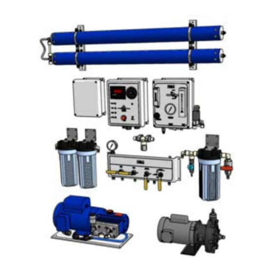
World Health Organization standards for potable water. System Overview This manual covers the entire WMS/WMSQ Series of watermakers. All of the machines in this series are made up of the same ten (10) basic components. The size and configuration of each component will vary but the function and name will remain the same throughout this manual. -
Page 8: Model/Serial Number Designation
Model/Serial Number Designation Each Watermakers Inc, system is given a unique model/serial number. This is so that if you ever need to call us for any reason we can look up your specific records to determine not only your watermakers date of manufacture and configuration, but also any factory service or upgrades/modifications that have been made. -
Page 9: System Specifications
WMS 550 2 MS AR NY1 Series/Type Capacity/GPD Electrical Power Controller Type Options Feed Pump System Specifications Model Production* Power Usage** Weight Membranes Number gpd/gph/lph volts/amps/kw lbs/kg Qty/Model# WMS-550 649/27.0/102.3 230/10.9/2.5 202/91.8 1/SW30-2540 WMSQ-550 660/27.5/104.1 230/14.5/3.3 304/138.2 1/SW30-2540 WMS-1000 1068/44.8/168.5 230/10.9/2.5 211/95.9 2/SW30-2540 WMSQ-1000 1044/43.5/164.7... -
Page 10: Installation
2. Installation... -
Page 11: Before You Begin
Before You Begin The WMS/WMSQ Series are modular systems designed to use less space and provide ease of operation and maintenance. Although every installation is unique, this section contains the typical sequence of steps required to complete the installation of your watermaker. The installation of this unit must be carried out carefully in order to ensure its long life and safe operation and to avoid damage to your vessel. -
Page 12: Installation
Location and Type of Overboard Thru-Hull: Above the waterline and not shared with other systems. Electrical Connections: The main power feed should be rated to carry the full load current of the unit with the proper size circuit breaker (see system specifications in Section 1. to determine your watermakers power consumption). -
Page 13: Mounting The Components
Now that you have a watermaker and a plan, you are ready to begin. The following instructions are broken down into the major steps required to complete the installation. All of the watermakers covered by this manual are made up of the same basic components the only difference is the physical size of each component. Figure 3 shows a typical installation of a WMS-550 with hose runs. - Page 14 Note: For ease of operation the electric panel, flow panel and valve panel should be mounted so that all three are within arm’s reach of the operator. All flow meters, pressure gauges and indicators should be visible from the operator’s position. E.
-
Page 15: Plumbing Connections
K. Product Diverter (PKG): 1. On WMS 550-1000 watermakers the PKG is already mounted to the side of the flow panel. For WMS 1400-3000 machines use the four (4) tapping screws provided to mount the PKG valve assembly to the bulkhead in a location along the planned tubing run between the salinity probe and the product inlet fitting on the flow panel. - Page 16 Figure 5...
- Page 17 1. Connect the charcoal filter inlet fitting to the fresh water system using the following; WMS-550-1000 ½” polybraid hose and clamp with two (2) clamps # 50-R-20 provided. WMS-1400-3000 ¾” polybraid hose and clamp with two (2) clamps # 50-R-28 provided.
- Page 18 4. Connect the product outlet fitting(s) on the flow panel to fresh water storage tank(s) using the following; WMS-550-1000 ⅜” poly tubing provided. WMS-1400-3000 ½” poly tubing provided. WMS/WMSQ-550 thru 1000 Figure 6 WMS/WMSQ-1400 thru 3000 Figure 7...
- Page 19 E. High Pressure Hose Connections: 1. Assemble one end fitting onto the high pressure hose. Refer to Fig 8. a. Clamp the socket portion of the hose end fitting in a vise. b. Thread hose counterclockwise until the hose bottoms in the fitting, back hose out ¼ turn clockwise.
-
Page 20: Electrical Connections
3. Electrical Connections: USE EXTREME CAUTION! : While making connections to and while servicing the electrical parts of your watermaker. Disconnect all electrical power before attempting to wire the panel or when the panel is open for any reason. CAUTION! : Depending on the electrical configuration some units may be powered from two separate sources, always double check with a meter before working on or around open electrical control panels. - Page 21 If 115VAC power is available make the connections in the contactor box as shown in the drawings that came with your watermaker. If 115VAC power is not available, a transformer box such as those available from Watermakers Inc. must be installed and connected in accordance with the manufacturer’s instructions.
-
Page 30: Operating Instructions
3. Operating Instructions... -
Page 32: Operating Your Watermaker
Operating Your Watermaker The following procedures will guide you through the normal operation, start-up, shut-down and rinsing of your watermaker. The following drawings and descriptions should help to familiarize you with the location and names of the controls (valves and switches etc.) required for the operation of the watermaker. If you have purchased any optional upgrades take some time and review the instructions that came with them as they may affect the operation of your watermaker. - Page 33 VP-050 Valve Panel WMS/Q-550 thru 1400 1. Feed Pressure Gauge 2. Freshwater Rinse 3. Clean Intake 4. Operate Seawater 5. Brine Overboard/Clean Discharge Figure 11 VP-1000 Valve Panel WMS/Q-1700 thru 3000 1. Feed Pressure Gauge 2. Clean Feed 3. Freshwater Feed 4.
-
Page 34: Initial Start-Up
A. Open the Seawater Feed valve on the Valve Panel. B. Divert reject to overboard on WMS-550-1400 place the Reject Valve in the Brine Overboard position on the VP-050 or on WMS1700-3200 open the Overboard Discharge and close the Clean Discharge on the VP-1000. -
Page 35: Normal (Manual) Shutdown
A. Test the freshwater supply for residual chlorine, using the sample port on the charcoal filter and a chlorine test kit (Watermakers, Inc. Part # CL-1A). B. Close the Seawater Feed Valve on the valve panel. -
Page 36: Operator's Log Sheet
CAUTION: Extreme caution should be taken when using the following procedure, especially when operating in areas such as the Gulf Stream where temperature changes of as much as 20 degrees can occur in just a few minutes. A. Monitor the product flow rate as indicated by the flow meter. B. - Page 37 Watermaker Performance Log Model Number: ______________________ Serial Number: ______________________ Product Reject Operating Product Feed Water Feed Water Date Flow Flow Pressure Conditions Temperature...
-
Page 38: Maintenance Instructions
4. Maintenance Instructions... -
Page 40: Maintaining Your Watermaker
Pre-Filters should be replaced before the feed pressure as indicated on the Feed Inlet gauge drops to 10 psi. There are 2 different sizes of prefilter elements used in the WMS series of watermakers, 2-1/2” and 4” diameter. The housings for both sizes while different in size consist of the same basic parts and are assembled the same. -
Page 41: Membrane Cleaning
There are 2 different sizes of prefilter elements used in the WMS series of watermakers, 2-1/2” and 4” diameter. The housings for both sizes while different in size consist of the same basic parts and are assembled the same. The 4” version is shown below. - Page 42 N. Once the pump has run for the allotted time, turn the rotary switch to OFF. O. Empty the bucket by, WMS-550-1400 placing the Reject Valve in the Brine Overboard position on the VP-050. On WMS-1700-3200 open the Overboard Discharge and close the Clean Discharge on the VP-1000.
-
Page 43: Long Term Storage
Note: Use only Watermakers, Inc. approved sanitizing solution. The chemical is premixed in the exact amounts required for maximum protection. Using other types could result in damage to membranes and other internal equipment. -
Page 44: Winter Storage
O. Empty the bucket by, WMS-550-1400 placing the Reject Valve in the Brine Overboard position on the VP-050 or on WMS1700-3200 open the Overboard Discharge and close the Clean Discharge on the VP-1000. Turn the rotary switch to the ON position. - Page 45 A. WMS-550-1700 1. End Cap (VC-107B) 2. Pressure Vessel (PV-FBGL-2540) 3. Retaining Pin (RP-107) 4. Retaining Clip (4109) 5. Membrane Element (SW30-2540) 6. Brine Seal (80042) 7. Product Port O-Ring (4005) 8. End Cap O-ring (4004) Figure 15 1. Membrane Removal.
- Page 46 B. WMS-2200-3000 1. Retaining Ring (45260) 2. End Plug Assy (47476) 3. Product Port Adptr (104075) 4. Membrane Element (SW30-4040) 5. Pressure Vessel (PV-GLASS-4040) 6. Brine Seal (80050) 7. End Plug O-ring (A-342-EP) 8. Product Port O-Ring (A-114-EP) Figure 16 9.
-
Page 47: High Pressure Pump
E. Check oil for water, metal or other contaminants as this could be a sign of larger problems. F. Replace oil drain plug. G. Immediately refill pump with one (1) U.S. quart of Hydra-Oil (watermakers part# 4233). H. Replace the oil fill cap. - Page 48 There are two methods for calibrating the sensor input, either one will work on any Watermakers Inc machine using the EP-2016. Read the following procedures carefully and determine which one is best for you.
- Page 49 Suspend the probe by the cable so that the surface of the probe is just submerged in the calibration solution (Watermakers Inc. part# 300). d. Start the watermaker by performing steps A-D of the normal start up procedure in section 3 of this manual.
-
Page 50: Spare Parts Quick Reference
The following is a list of part numbers for the most commonly used spare/replacement parts for the WMS/WMSQ Series machines. Our Parts Department and Service Technicians will be glad to advise you on what to keep on hand for your particular needs. Description Watermakers Part # 5m Prefilter 2-1/2”x10” CP-5 5m Prefilter 4”x10”... -
Page 52: Troubleshooting
5. Troubleshooting... -
Page 54: Troubleshooting Guide
Troubleshooting Guide Problem Possible Cause Corrective Action Unit will not start No power Check main power source. Check main breaker closed. Blown control power fuse on circuit board in EP Incorrect or low voltage Meter main power source. Loose or incorrect electrical Check and tighten all electrical connections. connections. - Page 55 Refer to high pressure pump repair section in manual. plunger in high pressure pump. Dirty pump oil. Change pump oil. If problem persists contact Watermakers Inc. for Diesel flush instructions. Air in feed lines. Check all feedwater lines for loose connections and broken fittings.
-
Page 56: Appendices
6. Appendices... - Page 58 4024 Feed Pump * Motor part # varies with watermaker model. Contact watermakers, Inc. for correct part number. Part Description Qty. Watermakers Inc. Part No. Flat Washer 3/8FW Lower Mounting Bolt 3/8X1HHCS Upper Mounting Bolt 3/8X3/4HHCS 4024 Mount 4045 Shaft Seal...
- Page 63 Troubleshooting SPNC/SPE...
-
Page 88: Warranty And Service
7. Warranty and Service... - Page 90 LIMITED WARRANTY Watermakers, Inc. warrants that each Watermaker’s Inc., system has been factory tested to perform in accordance with published specifications at the time of delivery. The Company further warrants that the Watermaker will continue to make potable water for a period of one...
-
Page 91: Warranty/Service Policy
CHEMICALS, AND ACTS OF GOD WILL VOID THE WARRANTY. Contact Information To Order Parts visit www.watermakers.com and click on the Parts Tab to use the online order form. For Sales, Service and Technical inquiries, e-mail info@watermakers.com Or, contact us direct at the factory: Watermakers, Inc.
Need help?
Do you have a question about the WMS-550 and is the answer not in the manual?
Questions and answers