Table of Contents
Advertisement
Quick Links
Advertisement
Table of Contents

Summary of Contents for ITW Gema OptiControl CM-20
- Page 1 Operating instructions and spare parts list OptiControl CM-20...
- Page 2 To the best of our knowledge and belief, the information contained in this publication was correct and valid on the date of issue. ITW Gema AG makes no representations or warranties with respect to the contents or use of this publication and reserves the right to revise this publication and make changes to its content without prior notice.
-
Page 3: Table Of Contents
Product specific security measures ..............12 About this manual General information ....................13 Software-Version ....................13 Function description Field of application ....................15 Technical Data OptiControl CM-20 ....................17 General ....................17 Electrical data ..................17 System .....................17 Display .....................18 Dimensions ....................18 Operating and display elements Operation ......................19 Front side ......................19... - Page 4 Check digital inputs and set and delete outputs........... 61 User levels and access Log-in........................65 User level 0......................65 User level 1......................65 User level 2......................66 User level 3......................66 No user level......................66 2 • Table of contents OptiControl CM-20...
- Page 5 Time, date, language, user, brightness ...........68 Schematic diagrams Wiring diagram ......................71 Spare parts list Ordering spare parts .....................73 OptiControl CM-20 - spare parts list ..............74 OptiControl CM-20 - spare parts................75 OptiControl CM-20 - spare parts (rear side) ............76 Table of contents • 3 OptiControl CM-20...
-
Page 7: General Safety Regulations
V 03/06 General safety regulations This chapter sets out the fundamental safety regulations that must be followed by the user and third parties using the OptiControl CM-20 control unit. These safety regulations must be read and understood before the OptiControl CM-20 control unit is used. -
Page 8: Technical Safety Regulations For Stationary Electrostatic Powder Spraying Equipment
V 03/06 conformity of use. The OptiControl CM-20 should only be used, maintained and started up by trained personnel, who are informed about and are familiar with the possible hazards involved. 4. Start-up (i.e. the execution of a particular operation) is forbidden... -
Page 9: Safety Conscious Working
Individual safety regulations for the operating firm and/or operating personnel 1. Any operating method which will negatively influence the technical safety of the powder spraying equipment is to be avoided. General safety regulations • 7 OptiControl CM-20... -
Page 10: Notes On Special Types Of Hazard
Static charges Static charges can have the following consequences: Charges to people, electric shocks, sparking. Charging of objects must be avoided - see "Earthing". 8 • General safety regulations OptiControl CM-20... -
Page 11: Safety Requirements For Electrostatic Powder Coating
Repairs must only be carried out by specialists or in ITW-Gema workshops. Unauthorized conversions and modifications may lead to injury or damage to machinery. The ITW Gema AG guarantee would no longer be valid. Safety requirements for electrostatic powder coating 1. -
Page 12: A Summary Of The Rules And Regulations
If the UEG is not known then a value of 10 g/m³ should be used. A summary of the rules and regulations The following is a list of relevant rules and regulations which are to be observed: 10 • General safety regulations OptiControl CM-20... - Page 13 Supplementary definitions for stationary electrical spraying equipment DIN VDE 0147 Setting up stationary electrostatic spraying equipment Part 1 DIN VDE 0165 Setting up electrical equipment in locations in areas with danger of explosion General safety regulations • 11 OptiControl CM-20...
-
Page 14: Product Specific Security Measures
Before starting up the plant a check must be made to ensure that no foreign objects are in the booth or in the ducting (input and exhaust air) It must be observed, that all components are grounded according to the local regulations, before start-up 12 • General safety regulations OptiControl CM-20... -
Page 15: About This Manual
General information This operating manual contains all important information which you require for the working with the OptiControl CM-20 control unit. It will safely guide you through the start-up process and give you references and tips for the optimal use of your new powder coating system. -
Page 17: Function Description
Function description Field of application The OptiControl CM-20 is a master control unit. It is used exclusively for operating a powder coating system with the corresponding control units. Any other use of the product will be considered as non intended use. The manufacturer is not responsible for any damage resulting from this;... -
Page 19: Technical Data
V 03/06 Technical Data OptiControl CM-20 General OptiControl CM-20 Max. number of guns Gun control unit OptiTronic CG02 Max. number of reciprocators Reciprocator control unit CR04 Monitor size 5,7" Communication by CAN bus Operating temperature 0-40°C Storing temperature -20-60°C Protection type... -
Page 20: Display
V 03/06 Display OptiControl CM-20 Technology LCD STN color Resolution 320x240 Number of colors Display surface 118x89 mm Operation by infrared touch Front screen SVG, anti reflex coated, scratch-proof Dimensions OptiControl CM-20 Width 406 mm Depth 275 mm Height 178 mm Weight 9.3 kg... -
Page 21: Operating And Display Elements
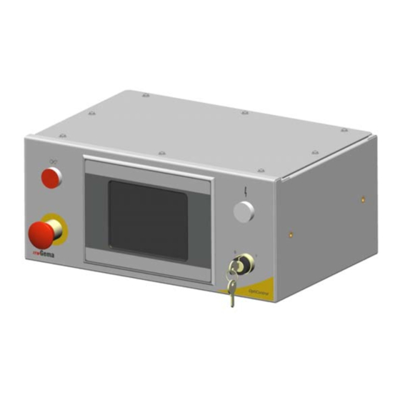
Additionally, the following described switches and displays are available. Front side OptiControl CM-20 - operating and display elements Key switch (control voltage ON/OFF) Emergency stop key (plant switch off in emergency case) Illuminated push button (malfunction acknowledgement) -
Page 22: Rear Side
V 03/06 Rear side OptiControl CM-20 - operating and display elements (rear side) AUX Internal control signals connection CAN IN CAN OUT Parasitic control current circle connection There is the possibility of connecting a parasitic control current circle, additionally to the internal emergency stop control current circle. -
Page 23: Start-Up
Start-up General information The OptiControl CM-20 plant control is parameterized, configured and tested at the ITW Gema premises. This allows a faster start-up, because less parameters must be locally adjusted. The application data in the laboratory report offer an additional assistance, because these can be used as basic adjustment for guns and reciprocators. -
Page 24: Function Keys
Function keys Open / close the cone caps 1. Press the key . The cone caps open. 2. Press the key . The cone caps close. Error acknowledgement, alarm horn switches off. Menu structure Menu structure 22 • Start-up OptiControl CM-20... -
Page 25: Starting The Equipment
1. Switch on the main switch on the plant control cabinet. Switch on the control voltage by key switch, the illuminated element on the OptiControl CM-20 shines. The OptiControl CM-20 starts the operating system now, the PLC control and the operating software until to starting page. -
Page 26: Log-In
Error page for logging in Main page logged in 3. Press the key All axes move to their reference point position. 4. Press the key Equipment switches to manual operating mode and the following page is displayed: 24 • Start-up OptiControl CM-20... -
Page 27: Parameterization Of The Equipment
V 03/06 Manual operating mode Parameterization of the equipment Press the key The following page is displayed: Main page parameterization Start-up • 25 OptiControl CM-20... -
Page 28: Starting Points Of Axes And Guns
Powder hose length correction Press the key The following page is displayed: Powder hose length correction 1. Determine and enter the minimum powder output (FL_min) and correction value (SKW%) in accordance to the OptiTronic CG02 operating instructions 26 • Start-up OptiControl CM-20... -
Page 29: Pretravel And Overtravel Of Axes And Guns
2. Calibrating a measuring section of 2 meters with the indication of the time needed for it by pressing the start key 3. Calibrating by indicating the current conveying speed and by pressing the start key Start-up • 27 OptiControl CM-20... -
Page 30: Segmentation Of The Light Grid, Masking The Light Grid
The following page is displayed: Light grid evaluation for gun shutdown 1. Light grid distance is the distance between two light grid widths 2. Spraying distance is the shortest spraying distance needed on the equipment 28 • Start-up OptiControl CM-20... -
Page 31: Segmentation Of The Light Grid, Light Grid Distance, Minimum Spraying Distance
Press the key The following page is displayed: Segmentation of the light grid, light grid distance, minimum spraying distance Touch fields on main page Main page Activated touch key fields Light grid information Start-up • 29 OptiControl CM-20... -
Page 32: Touch Fields One Level Lower
Edit axis values, select or deselect axes Edit gun values and select or deselect, daily correction Conveyor simulation, if conveyor does not run or CAN bus sensor is not installed or defective Start and stop guns Start and stop axes 30 • Start-up OptiControl CM-20... -
Page 33: Start And Stop Axes, Select Or Deselect
Edit and start axes For details, see chapter "Operating modes" Select and deselect guns, daily correction Press the key The following page is displayed: Select and deselect guns, daily correction For details, see chapter "Operating modes" Start-up • 31 OptiControl CM-20... -
Page 34: Edit Gun Values
Press the key The following page is displayed: Light grid information 1. Display of the width on the left and on the right 2. Display of the lowest interrupted beam 3. Display of the segments 32 • Start-up OptiControl CM-20... -
Page 35: Equipment In Automatic Operation Mode
The following page is displayed: Automatic operation mode The workpieces are coated in a fully automated operating mode. Guns switch on if required, and the axes travel to the entered positions. Automatic operation mode - one level lower Start-up • 33 OptiControl CM-20... -
Page 37: Operating Modes
Edit axis values, select or deselect axes Edit and select or deselect gun values, daily correction Conveyor simulation, if the conveyor does not run or CAN bus sensor is not installed or defective Start and stop guns Operating modes • 35 OptiControl CM-20... - Page 38 V 03/06 Start and stop axes Select Automatic operating mode Select Manual operating mode Select Cleaning operating mode Select Service operating mode Information All Axes are referenced 36 • Operating modes OptiControl CM-20...
-
Page 39: Manual Operating Mode
V 03/06 Manual operating mode Press the key The following page is displayed: Manual operation main page Press the large touch field in the middle The following page is displayed: Manual operating mode Operating modes • 37 OptiControl CM-20... -
Page 40: Edit Axis Values, Select Or Deselect Axes
Only selected axes can be started 2. Press the key The axes start 3. Press the key The axes stop 4. The input fields allow the user to modify the position of the axes 38 • Operating modes OptiControl CM-20... -
Page 41: Select Or Deselect Guns And Daily Correction
2. The input fields allow the user to modify the gun values Edit gun values Press the key The following page is displayed: Edit gun values 1. Modify daily correction value for each station 2. Select or deselect guns Operating modes • 39 OptiControl CM-20... -
Page 42: Axes Start Independently From The Conveyor
Axes start independently from the conveyor 1. Press the key The key turns green and the activated conveyor is simulated 2. Press the key The key turns green and the reciprocators move, if the axes are selected 40 • Operating modes OptiControl CM-20... -
Page 43: Guns Start Independently From The Conveyor
Guns start independently from the conveyor 1. Press the key The key turns green and the activated conveyor is simulated 2. Press the key The key turns green and the guns spray powder, if the guns are selected Operating modes • 41 OptiControl CM-20... -
Page 44: Automatic Operation Mode
Object changes are carried out manually or automatically Daily correction of the powder output can be modified Guns can be selected or deselected Light grid can be controlled See chapter "Manual operation mode" 42 • Operating modes OptiControl CM-20... -
Page 45: Simulation Of The Can Bus Sensor
Once the X axes reached the position, the waiting period runs down. Subsequently, the X axes travel out of the booth and the outer cleaning valves are opened. 3. Press the key The internal gun cleaning is started and the key turns green Operating modes • 43 OptiControl CM-20... - Page 46 Following page is displayed: Cleaning operation one level lower Press the key The following page is displayed: Cleaning positions of the axes Enter the cleaning positions and speed Enter the waiting time for the external cleaning 44 • Operating modes OptiControl CM-20...
-
Page 47: Service Operation
Check the light grid Press the key The following page is displayed: Light grid information Display of the width on the left and on the right Display of the lowest interrupted beam Display of the segments Operating modes • 45 OptiControl CM-20... -
Page 48: Administration Of Operating Hours
The following page is displayed: Main page operating hours Operating hours of the different operating modes are displayed Operating hours fan Operating hours axes Operating hours guns Press the key The following page is displayed: Operating hours 46 • Operating modes OptiControl CM-20... - Page 49 When the actual value reaches the nominal value, an error message is displayed 2. Press the key The actual value is added to the total value and set to zero Lamp test Parameterization of the equipment Operating modes • 47 OptiControl CM-20...
-
Page 50: Parameterization
Press the key The following page is displayed: Main page parameterization General parameters Station parameters Calibration of the CAN bus sensor Booth parameters Light grid parameters for gun switch-off Light grid parameters for stroke switching 48 • Operating modes OptiControl CM-20... -
Page 51: General Parameters
Time until error light and alarm turn off Pulse length warning light off Time until error light and alarm turn on Delay of messages Time from the occurrence of an error to the display on the screen Operating modes • 49 OptiControl CM-20... -
Page 52: Station Parameters
Starting points of axes and guns Press the key The following page is displayed: Starting points Adjust starting points, pretravel and overtravel: 1. Modify starting points for each gun 2. Modify starting points for each axis 50 • Operating modes OptiControl CM-20... -
Page 53: Powder Hose Length Correction
Pretravel and overtravel of axes and guns Press the key The following page is displayed: Pretravel and overtravel of axes and guns 1. Adjust pretravel and overtravel for each axis 2. Adjust pretravel and overtravel of the guns Operating modes • 51 OptiControl CM-20... -
Page 54: Calibration Of The Can Bus Sensor
3. Calibrating by indicating the current conveying speed and by pressing the start key 4. Calibrating by indicating the drive shaft diameter and by pressing the start key Adjust the preceding sign of the CAN bus sensor 52 • Operating modes OptiControl CM-20... -
Page 55: Light Grid Segmentation, Masking The Light Grid
Spraying distance is the shortest spraying distance needed on the equipment Light grid segmentation, light grid distance, minimum spraying distance Press the key The following page is displayed: Light grid distance and spraying distance Operating modes • 53 OptiControl CM-20... -
Page 56: Various Parameters
If there is no object detected during this distance, the X axes travel out of the booth and the outer cleaning valves blow off the guns Pretravel and overtravel: - Guns external coating - Guns internal coating - Object 54 • Operating modes OptiControl CM-20... -
Page 57: Object Data Administration
Object data administration Load and save object data Press the key The following page is displayed: Load object data Line up Line down Save object data Copy data to clipboard Copy data from clipboard Object data administration • 55 OptiControl CM-20... -
Page 58: Copy And Insert Object Data
5. Press the key Object data is loaded 6. Press the key Object data is copied to the current object 7. Press the key Object data is saved 56 • Object data administration OptiControl CM-20... -
Page 59: Name Object Data
V 03/06 Name object data The screen keyboard is opened by pressing the table field. With the help of this, the record can be inscribed. Indicate object data Object data administration • 57 OptiControl CM-20... -
Page 61: Error Display
Press the key The following page is displayed: Error page Line up Line down Display error history Delete inactive error messages from the list and acknowledge errors Display of the active CAN bus devices Error display • 59 OptiControl CM-20... -
Page 62: Active Can Bus Devices
The following page is displayed: Active CAN bus devices - first page Press the key The following page is displayed: Active CAN bus devices - second page Fields colored in green show active CAN bus devices. 60 • Error display OptiControl CM-20... -
Page 63: Check Digital Inputs And Set And Delete Outputs
Powder center CPU Booth knot Light grid knot Sensor Powder center panel Check digital inputs and set and delete outputs Press the key The following page is displayed: Main page - digital inputs and outputs Error display • 61 OptiControl CM-20... - Page 64 V 03/06 Press the key The following page is displayed: Input page Press the key The following page is displayed: Input page 62 • Error display OptiControl CM-20...
- Page 65 V 03/06 Press the key The following page is displayed: Set and delete digital outputs Press the key The key turns green and the output is set. Error display • 63 OptiControl CM-20...
-
Page 67: User Levels And Access
After 3 minutes, the system logs out automatically User level 1 No configuration possible Plant parameters and object-related data (gun and axis data) can be modified After 30 minutes, the system logs out automatically User levels and access • 65 OptiControl CM-20... -
Page 68: User Level 2
The user can only activate existing object data, modify the daily correction and deselect guns If no user is announced, the user panel is locked No automatic log out No user level Logged out status 66 • User levels and access OptiControl CM-20... -
Page 69: Plant Configuration
V 03/06 Plant configuration General information Start page Plant configuration • 67 OptiControl CM-20... -
Page 70: Adjustments
Press the key The following page is displayed: Main page configuration 1. Set time 2. Select system language German / English OptiControl CM-20 plant control Important: restart 3. Select project language The following languages are available: Languages 4. Show all users 5. - Page 71 Backup of the configuration is filed under “99 Backup“ General configuration parameters of the plant Station definition, axes and guns with system parameters Release the four available calibration options of the CAN bus sensor Booth definition Set type of object recognition Plant configuration • 69 OptiControl CM-20...
-
Page 73: Schematic Diagrams
V 03/06 Schematic diagrams Wiring diagram Error acknowledgement Status lamp control voltage Key switch control voltage External emergency Emergency stop stop clamps. Capacity: max. 240 VAC / 1 A OptiControl CM-20 - wiring diagram Schematic diagrams • 71 OptiControl CM-20... -
Page 75: Spare Parts List
WARNING! Only original ITW-Gema spare parts should be used as the explosion protection will also be preserved that way. The use of spare parts from other manufacturers will invalidate the ITW Gema guarantee conditions! Spare parts list • 73 OptiControl CM-20... -
Page 76: Opticontrol Cm-20 - Spare Parts List
V 03/06 OptiControl CM-20 - spare parts list OptiControl CM-20 - complete 1002 350 Micro Touch Panel - MC2-5,7", complete 269 174 Key switch 3, central position 268 038 Switch lower part - complete, maker 267 821 Warning lamp - 24 VDC, white... -
Page 77: Opticontrol Cm-20 - Spare Parts
V 03/06 OptiControl CM-20 - spare parts OptiControl CM-20 - spare parts Spare parts list • 75 OptiControl CM-20... -
Page 78: Opticontrol Cm-20 - Spare Parts (Rear Side)
V 03/06 OptiControl CM-20 - spare parts (rear side) OptiControl CM-20 - spare parts (rear side) 76 • Spare parts list OptiControl CM-20... - Page 79 V 03/06 Spare parts list • 77 OptiControl CM-20...
Need help?
Do you have a question about the OptiControl CM-20 and is the answer not in the manual?
Questions and answers