Table of Contents
Advertisement
Quick Links
Description:
Spraytronic 3
Type:
Manual
File:
Do210004 Spraytronic 3 V18 EN.docx
VDH Products BV
Produktieweg 1 9301 ZS Roden
PO Box 2059300 AE Roden The Netherlands
T +31(0)50 302 89 00 | F +31 (0)50 302 89 80
info@vdhproducts.nl
|
www.vdhproducts.nl
Spraytronic 3 Manual
Spray booth controller
Pages:
By:
MC3 software:
BP software:
62
Doc.no:
JB
Version:
200673 v1.15
Date:
210002 v1.05
210004
1.8
07-12-2022
Advertisement
Table of Contents

Subscribe to Our Youtube Channel
Related Manuals for VDH Spraytronic 3


Summary of Contents for VDH Spraytronic 3
- Page 1 Description: Spraytronic 3 Pages: Doc.no: 210004 Type: Manual Version: File: Do210004 Spraytronic 3 V18 EN.docx MC3 software: 200673 v1.15 Date: 07-12-2022 BP software: 210002 v1.05 VDH Products BV Produktieweg 1 9301 ZS Roden PO Box 2059300 AE Roden The Netherlands T +31(0)50 302 89 00 | F +31 (0)50 302 89 80 info@vdhproducts.nl...
-
Page 2: Table Of Contents
Spraytronic 3 Documentnr.: 210004 Version 1.8 Table of contents Introduction ................................ 5 Control modes ..............................6 On, Off & Cooldown ..........................6 Standby ............................... 6 Spray ................................6 Dry & Cool ..............................7 Quickdry ..............................8 Flash-off ..............................8 Temperature control ............................9 Analog heating control .......................... - Page 3 Spraytronic 3 Documentnr.: 210004 Version 1.8 Alarms................................. 20 10 Touchpanel ................................ 23 10.1 Default ............................... 23 10.2 Settings ..............................23 10.3 Menu ................................26 11 Parameters ............................... 35 12 Input and output functions ........................... 43 12.1 Temperature functions ......................... 43 12.2...
- Page 4 Spraytronic 3 Documentnr.: 210004 Version 1.8 Tables Table 1 Overview of control modes with corresponding settings..............13 Table 2 Overview non-fatal alarms........................21 Table 3 Overview fatal alarms..........................22 Table 4 Overview of control mode symbols....................... 24 Table 5 Overview system tray icons.
-
Page 5: Introduction
These booths are e.g. typically used to (re)paint automotive objects such as parts/panels. However, the Spraytronic 3 controller is not limited to any particular object. The Spraytronic 3 controller has a variety of configuration options which can be used to adapt to different situations and requirements. -
Page 6: Control Modes
Spray control mode is automatically activated and remains active for P156 minutes. The duration of compressed air usage For example VDH products; IRS sensor (909.000002) with Alfa 1-IRS (904.010009). Page 6 of 62... -
Page 7: Dry & Cool
Spraytronic 3 Documentnr.: 210004 Version 1.8 (detection) must be at least P157. The Spray control mode cannot be activated, or set, during Dry or Quickdry. With the Compressed air enable relay the compressed air can automatically ‘blocked’ to disable spraying. The compressed air enable relay is set during the control modes Standby and Spray. -
Page 8: Quickdry
Spraytronic 3 Documentnr.: 210004 Version 1.8 Figure 1 Temperature control example during a Dry & Cool process. Figure annotations: t1=start Dry, t2=30 sec. delay ends, t3=start dry-time (P2=35ºC P22=1min.), t4=stop burner (P20=1min.), t5=end dry-time & start Cool (P5=4min.), t6=end Cool & start Standby (P4=7ºC), t7=temperature below P1. -
Page 9: Temperature Control
Spraytronic 3 Documentnr.: 210004 Version 1.8 3 Temperature control To obtain the temperature setpoint a heating actuator (e.g. burner or electric heater) is controlled through an analog signal or through relays that activates a high-, low- or off-state. If both the Channel (booth supply air) temperature- and Booth temperature sensors are configured, the control- or process value (the value which is compared to the active setpoint) is as listed in Table 1. -
Page 10: Hot Water Heating
Spraytronic 3 Documentnr.: 210004 Version 1.8 In previous examples, bear in mind that the process/control value does not remain constant in reality. Typically a burner/heater provides a signal to indicate that it is operational, or on, without problems. This signal should be connected to the digital input Heating feedback. If this input is not set, the burner/heater analog output will also not be set. -
Page 11: Hybrid Heating
Spraytronic 3 Documentnr.: 210004 Version 1.8 Heating switches from low to high (High/low burner high-low on) when the temperature drops below setpoint – P44 + offset. The heating switches from high to low when the temperature has risen above setpoint – P44 + offset + 0.5. -
Page 12: Heat Recuperator Bypass Valve
Spraytronic 3 Documentnr.: 210004 Version 1.8 3.5 Heat recuperator bypass valve In some projects a heat exchanger may be installed to preheat the supply air stream with exhaust air from the booth to improve energy efficiency of the system, such a heat exchanger is also called a recuperator . -
Page 13: Table 1 Overview Of Control Modes With Corresponding Settings
Spraytronic 3 Documentnr.: 210004 Version 1.8 Supply Control Temp. Recirculation Recirculation Recirculation Temp. Recirculation temp. PI-control damper damper relay 1 damper relay 2 setpoint valve speed sensor Burner/heater (fresh air inlet) (inlet) (outlet) Off (ventilate) Off (close) On (open) Standby Booth P14 &... -
Page 14: Pressure Control
Spraytronic 3 Documentnr.: 210004 Version 1.8 4 Pressure control If an exhaust fan is driven by a variable-frequency drive, the booth pressure may be controlled by varying its speed while the supply fan speed remains constant. This may be done manually explained in section 4.1, or automatically, explained in section 4.2. -
Page 15: Control Valve
Spraytronic 3 Documentnr.: 210004 Version 1.8 While the exhaust fan control is ‘frozen’ the Recirculation valve enable relay is no longer set. This relay should be used in series with the Recirculation valve relay to temporarily stop, or disable, the Recirculation valve while the exhaust fan speed control is frozen. -
Page 16: Humidity Control
Documentnr.: 210004 Version 1.8 5 Humidity control The Spraytronic 3 is able to control a Munters FA6™ Evaporative humidifier . A three stage control system for designs with circulating water is available to maintain a relative humidity (RH) between an upper limit (P204) and a lower limit (P205). -
Page 17: Drain Valve
Spraytronic 3 Documentnr.: 210004 Version 1.8 seconds. The water inlet (valve) relay is set (open) again if the Level switch remains not active for P214. 5.4 Drain valve The drain valve (tray) relay is set (open) when the Spraytronic is turned off, otherwise it is not set (closed). -
Page 18: Filter Saturation
This feature is enabled, or disabled, with P167. The filter status is shown with a symbol, unlike the alarm when a pressure sensor is used. For example a PX25-4 differential pressure gauge type 1 (VDH nr. 910.080165). Set S1=off, S2=on, S3=off, S4=on (0 – 500 Pa). -
Page 19: Air-Thrusters
Spraytronic 3 Documentnr.: 210004 Version 1.8 7 Air-thrusters To accelerate the dry process, additional airflow may be added to the object within the booth through blowing air through several air- spouts/nozzles typically placed in the corner(s) of the booth. This feature is referred to as air-thrusters and are switched on- or of through the Corner air-thrusters relay. -
Page 20: Alarms
Spraytronic 3 Documentnr.: 210004 Version 1.8 9 Alarms Table 3 lists the fatal alarms, in case of a fatal alarm, due to which the system cannot safely continue, the controller is automatically turned Off and the background of the default screen turns red while a yellow symbol with exclamation mark will be shown as shown in Figure 8 in the upper right region. -
Page 21: Table 2 Overview Non-Fatal Alarms
Spraytronic 3 Documentnr.: 210004 Version 1.8 [Label] filter (1) max. spray-hours, Number of spray hours >P193. please replace* [Label] filter (2) max. spray-hours, Number of spray hours >P194. please replace* [Label] filter (3) max. spray-hours, Number of spray hours >P195. -
Page 22: Table 3 Overview Fatal Alarms
Spraytronic 3 Documentnr.: 210004 Version 1.8 Fatal alarm text Cause Internal temperature board failure Internal temperature board failure. Internal analog-in board failure Internal analog-in board failure. Internal digital-in board failure Internal digital-in board failure. Internal analog-out board failure Internal analog-out board failure. -
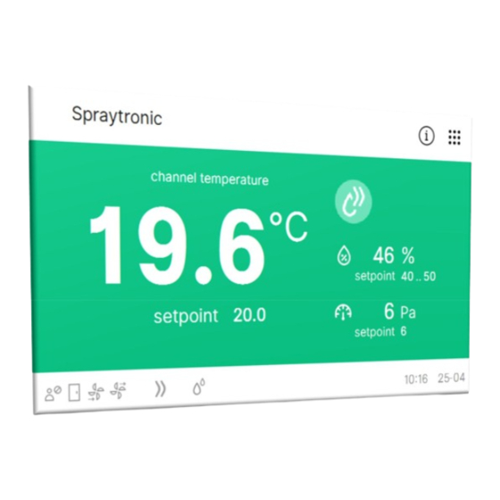
Page 23: Touchpanel
Spraytronic 3 Documentnr.: 210004 Version 1.8 10 Touchpanel A touchscreen control-panel may be used for local operation of the system. After applying power to the controller and touchscreen, the default screen will be shown, see Figure 4. If there is no communication with the controller a warning will appear with the (Red) text No communication in this case check the Ethernet connections and the IP addresses. -
Page 24: Table 4 Overview Of Control Mode Symbols
Spraytronic 3 Documentnr.: 210004 Version 1.8 Spray Manual (Spray) Automatic (Spray) Flash Off Quickdry Cooldown with thermostat Cool or Cooldown Table 4 Overview of control mode symbols. Not logged-in User logged-in (P903) Admin logged-in (P902) Door is closed Door is open... - Page 25 Spraytronic 3 Documentnr.: 210004 Version 1.8 Custom system name Open status window Currently active control/process description: booth or channel . Dry symbol Menu button Control/process temperature value Booth RH Booth RH lower limit Booth RH upper limit Remaining time of current control mode...
-
Page 26: Menu
Spraytronic 3 Documentnr.: 210004 Version 1.8 10.3 Menu By pressing the dots in the upper right corner the menu window is shown, see Figure 6. This menu provides buttons for various settings and configuration windows, the options are listed below. - Page 27 Spraytronic 3 Documentnr.: 210004 Version 1.8 Additional control-unrelated system-options are available via the gear button in the upper right corner of the menu, see Figure 13. These are described below. · Network. The touchpanel and the (MC3) controller communicate with each other via TCP/IP over Ethernet, the touchpanel needs the IP address of the corresponding (MC3) controller which can be set through this window.
- Page 28 Spraytronic 3 Documentnr.: 210004 Version 1.8 System-options Figure 6 Menu window. Figure 5 Parameters window. Page 28 of 62...
- Page 29 Spraytronic 3 Documentnr.: 210004 Version 1.8 Setpoints/Runtimes are equivalent with parameters in group 0. Figure 7 Temperature setpoints window. Figure 8 Alarm window. Page 29 of 62...
- Page 30 Spraytronic 3 Documentnr.: 210004 Version 1.8 Temperature status Pressure and airflow status Humidity status Air filter pressure status Figure 10 Temperature status window. Figure 9 Pressure and airflow status Page 30 of 62...
- Page 31 Spraytronic 3 Documentnr.: 210004 Version 1.8 Filter pressure below the warning setpoint (green) Filter pressure at 4 mA Filter pressure at 20 mA Filter pressure has exceeded the warning setpoint (yellow) Filter ID nr. Filter pressure has exceeded Filter pressure adjustable label...
- Page 32 Spraytronic 3 Documentnr.: 210004 Version 1.8 Figure 13 System settings window. Reset control mode operating hours to 0. Control mode operating hours Maintenance date Filter spray hours Figure 14 Control mode operating hours. Page 32 of 62...
- Page 33 Spraytronic 3 Documentnr.: 210004 Version 1.8 Figure 15 Maintenance date. Intake filter spray-hours Maximum intake filter spray-hours (P193) Reset intake filter spray-hours to 0. Filter adjustable label Filter ID nr. Figure 16 Filter spray hours. Page 33 of 62...
- Page 34 Spraytronic 3 Documentnr.: 210004 Version 1.8 Figure 18 Paycode. Figure 17 Network settings. Page 34 of 62...
-
Page 35: Parameters
Spraytronic 3 Documentnr.: 210004 Version 1.8 11 Parameters Through Menu -> Parameters; parameters can be adjusted. The table below shows an overview of the system parameters. Via the configuration webpage a backup of the current parameter set can be created by creating a backup. This set can be restored by selecting Other -> Restore Configuration ->... - Page 36 Spraytronic 3 Documentnr.: 210004 Version 1.8 Max. setpoint temperature -50.0 .. 120.0 °C 100.0 Max. temperature exceeding SP 0.0 .. 100.0 °C 10.0 Max. temperature exceeding SP time 1 .. 999 Sec. Offset booth temperature sensor -99.9 .. 99.9 Offset outside temperature sensor -99.9 ..
- Page 37 Spraytronic 3 Documentnr.: 210004 Version 1.8 Pressure control mode (0=manual 1=automatic 0 .. 2 2=none) Deadband pressure-control relative to SP 1.0 .. 5.0 Speed up/down supply fan [%/sec] 0.0 .. 10.0 Speed up/down exhaust fan [%/sec] 0.0 .. 10.0 Alarm at door open during dry/quickdry 0 ..
- Page 38 Spraytronic 3 Documentnr.: 210004 Version 1.8 Supply fan speed Dr3 0 .. 100 Group 10 Supply fan speed during Drying 1 .. 3 (1=Dr1 2=Dr2 3=Dr3) Supply fan speed during Spray 1 .. 3 (1=Sp1 2=Sp2 3=Sp3) Supply fan speed during Quickdry 1 ..
- Page 39 Spraytronic 3 Documentnr.: 210004 Version 1.8 Maximum exhaust fan speed at Sp2 0 .. 100 (manual and auto.) Maximum exhaust fan speed at Sp3 0 .. 100 (manual and auto.) Maximum exhaust fan speed at Dr1 0 .. 100 (manual and auto.) Maximum exhaust fan speed at Dr2 0 ..
- Page 40 Spraytronic 3 Documentnr.: 210004 Version 1.8 Max. spray hours air filter 1 0 .. 9999 Hour Max. spray hours air filter 2 0 .. 9999 Hour Max. spray hours air filter 3 0 .. 9999 Hour Max. spray hours air filter 4 0 ..
- Page 41 Spraytronic 3 Documentnr.: 210004 Version 1.8 IR sensor only during Dry modes (0=no1=yes) 0 .. 1 Group 25 Hybrid heat enable (1st hot water 2 0 .. 1 burner/heater) Hybrid heat burner/heater on-delay 0 .. 9999 Sec. Hybrid heat disable on-delay outside temp. SP -999.9 ..
-
Page 42: Table 6 Overview Parameters
Spraytronic 3 Documentnr.: 210004 Version 1.8 Air filter 3 pressure alarm 0 .. 9999 Air filter 3 pressure alarm delay 0 .. 9999 Sec. Air filter 3 pressure alarm is fatal 0 .. 1 Group 29 Air filter 4 pressure at 20 mA -9999 .. -
Page 43: Input And Output Functions
Spraytronic 3 Documentnr.: 210004 Version 1.8 12 Input and output functions 12.1 Temperature functions Description Code Channel (booth supply air) temperature (PT1000) Booth temperature (PT1000) Outside temperature (PT1000) Hot water supply (PT1000) Infrared temperature sensor Table 7 Overview temperature functions. -
Page 44: Relay Functions
Spraytronic 3 Documentnr.: 210004 Version 1.8 12.3 Relay functions Description Code Supply fan start Exhaust fan start Lights top Lights middle Lights bottom Burner/Heater on/off Burner/Heater enable Burner/Heater reset High/low burner on-off High/low burner high-low Recirculation valve enable Recirculation valve... -
Page 45: Digital-In Functions
Spraytronic 3 Documentnr.: 210004 Version 1.8 12.4 Digital-in functions Description Code Emergency stop Cooldown thermostat Door contact (pause pressure ctrl.) Isolation switch Compressed airflow (spray) detection (via ALFA 1-IRS) Heating feedback Booth pressure failure Burner/Heater failure Supply Fan failure Exhaust failure... -
Page 46: Connecting Ethernet
The default addresses of the controller(s) is 192.168.250.1, the default addresses of the corresponding touch-panel is 192.168.250.2. The IP address can be changed by using “VDH IP configurator” (VDH_Conf), available at the VDH website: www.vdhproducts.nl. This program can search for connected MC3 devices. Using the MAC address of the MC3 device. -
Page 47: Hardware Configuration
Spraytronic 3 Documentnr.: 210004 Version 1.8 15 Hardware configuration I/O channels can be assigned to various functions. I/O channels are defined by the position of the board (PCB) within the controller and the number of the channels on that PCB. The ordering of the PCB’s is as is shown in the next picture:... - Page 48 Spraytronic 3 Documentnr.: 210004 Version 1.8 Figure 20 IO overview example. Figure 21 ModBus access example. Figure 22 Hardware config example. Page 48 of 62...
- Page 49 Spraytronic 3 Documentnr.: 210004 Version 1.8 Using the Config overview button (Figure 20) all assigned channels are shown along available channels and configuration errors. Each board is identified by a serial number and its position within the controller, see Figure 22.
-
Page 50: Mc3 Software Update
Version 1.8 16 MC3 software update The MC3 controller software may be updated only if VDH Products B.V. explicitly instructs to do so. A user may through the webpage ( Other -> Install package ) upload a *.deb file received from VDH Products B.V. -
Page 51: Touchpanel Software Update
Spraytronic 3 Documentnr.: 210004 Version 1.8 17 Touchpanel software update Place the update (zip-)file on an USB stick and unzip/extract it. The USB-stick should now contain a directory named: “USB” which contains a directory named “mt8000ie”. Make sure this directory- structure is correct otherwise the update will not succeed. - Page 52 Spraytronic 3 Documentnr.: 210004 Version 1.8 Enter the correct password (111111) and press “Ok”. In the displayed window, select the directory “USB” (open "usbdisk", open"disk_a_1" and finally open "USB"). Press "Ok". The touch panel will update the software and show the text: “Download Project Files …”. After the software is updated, check the network settings.
-
Page 53: Connection Diagrams
Spraytronic 3 Documentnr.: 210004 Version 1.8 18 Connection diagrams 18.1 Processor board Page 53 of 62... -
Page 54: Analog-In/Out Board
Spraytronic 3 Documentnr.: 210004 Version 1.8 18.2 Analog-in/out board Page 54 of 62... -
Page 55: Relays & Digital-In Board
Spraytronic 3 Documentnr.: 210004 Version 1.8 18.3 Relays & Digital-in board Page 55 of 62... -
Page 56: Relay Board
Spraytronic 3 Documentnr.: 210004 Version 1.8 18.4 Relay board Page 56 of 62... -
Page 57: Digital-In Board
Spraytronic 3 Documentnr.: 210004 Version 1.8 18.5 Digital-in board Page 57 of 62... -
Page 58: Dimensions & Housing
Spraytronic 3 Documentnr.: 210004 Version 1.8 19 Dimensions & housing Figure 23 Spraytronic-3 controller (909.000060). Page 58 of 62... - Page 59 Spraytronic 3 Documentnr.: 210004 Version 1.8 Figure 24 Board positions. Page 59 of 62...
- Page 60 Spraytronic 3 Documentnr.: 210004 Version 1.8 Figure 25 Control panel (MT8071iE1) dimensions , connect 24 Vdc supply to (c), an Ethernet connection needs to be connected to (g). Use (e) to connect an USB stick with software update. Source: https://www.weintek.com/globalw/Product/Product_speciE.aspx...
-
Page 61: Document Revisions
Spraytronic 3 Documentnr.: 210004 Version 1.8 20 Document revisions Version Date Description 10-12-2020 Document created. 06-01-2021 Initial draft complete. 08-01-2021 Review. Added RH control. 22-04-2022 Added Flash-off control mode. Added recirculation dampers. 10-05-2022 Changed positions of recirculation damper relay 1 & 2. -
Page 62: Troubleshooting
The booth pressure sensor does not give For PX25-4 differential pressure gauge type 1 (VDH nr. 910.080165). Set S1=on, S2=off, S3=off, S4=on (0 the correct value. .. 250 Pa). To measure values below 0 Pa, use P51 and...
Need help?
Do you have a question about the Spraytronic 3 and is the answer not in the manual?
Questions and answers