Table of Contents
Advertisement
Quick Links
Advertisement
Table of Contents

Summary of Contents for Palazzoli Lewden ASPEN Series
- Page 2 Electric Vehicle AC Charger A S P E N Series - User Manual A S P E N A S P E N PRO IP55 Authorization Management Repairable Outdoor use Keep this user manual for future reference COPY RIGHT @ 2021 Lewden Ltd reserves the right to make changes to this product without further notice.
-
Page 3: Table Of Contents
CONTENT Important Safety Instructions ............1 1. User Interface ................4 1.1 ASPEN Edition 672140 ............4 1.2 ASPEN Pro Edition 672142 ..........5 2. Dimensions ..................6 2.1 Charger ..................6 2.2 Wall-Mounted Bracket ............6 3. Specification ................7 4. Design Standard ................8 5. Charger Status Indication Lights ..........9 6. -
Page 4: Important Safety Instructions
A S P E N Series - User Manual Important Safety Instructions Please read these Important Safety Instructions together with the charging instructions in your vehicle owner’s manual before charging your electric vehicle. The charging device is only suitable for vehicles that are compatible with the IEC 62196 charging standard. - Page 5 Green Power, Green Lifestyle. be exposed to flammable vapors. Do not operate the charger near explosive, corrosive, or combustible materials, chemicals, or vapors. • Always maintain a clean and clear area within the local vicinity of the charger. • Never store objects on the charger. •...
- Page 6 A S P E N Series - User Manual Safety Warning – Maintenance • Never carry out unauthorized changes or other technical modifications to the system. • Never use any replacement parts other than those approved by the manufacturer. • The mains supply to the charger must be isolated prior to carrying out any work on the charging installation.
-
Page 7: User Interface
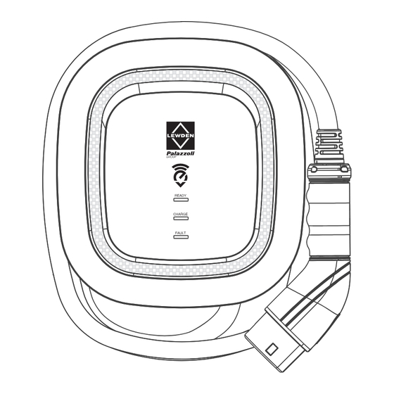
Green Power, Green Lifestyle. 1. User Interface 1.1 ASPEN Edition 672140 Front Indication lights IEC 62196 AC Charging Connector Rear Mounting Hook Charging Cable Inlet AC Power Inlet RJ45 Cable Inlet... -
Page 8: Aspen Pro Edition 672142
A S P E N Series - User Manual 1.2 ASPEN Pro Edition 672142 Front RFID Indication lights IEC 62196 AC Charging Connector Rear Mounting Hook Charging Cable Inlet AC Power Inlet RJ45 Cable Inlet... -
Page 9: Dimensions
Green Power, Green Lifestyle. 2. Dimensions (unit:mm) 2.1 Charger 2.2 Wall-Mounted Bracket Refer to sections 6.5 & 6.6 for installation notes. 189.7... -
Page 10: Specification
A S P E N Series - User Manual 3. Specification Model Name ASPEN / ASPEN pro 200-240 VAC / Single Phase Rated Input Voltage Rated Output Current Single Phase / 32A AC Power Frequency 50/60 Hz UVP <160VAC ±5V recovery >170VAC ±5V OVP >275VAC ±5V recovery <265VAC ±5V Input Protection RCD 30mA AC or >6mA DC... -
Page 11: Design Standard
Green Power, Green Lifestyle. *1 LAN Version WIFI Version *2 Wi-Fi Version Ground monitor interrupter Local area network Over current protection Over temperature protection Over voltage protection Residual current device RFID Radio frequency identification Surge protection device Under voltage protection Refer to 7.5 for further details of how these systems communicate fault and error messages on the charger. -
Page 12: Charger Status Indication Lights
A S P E N Series - User Manual 5. Charger Status Indication Lights Standby mode - Green Light The READY light is constantly lit. The charger is ready for use. RFID Authorization (Pro Edition only) - Green Light Flashing Green READY light is flashing after the RFID has been authorized using the activation card. - Page 13 Green Power, Green Lifestyle. Charging - Blue Light Flashing The CHARGE light flashes whilst the vehicle is charging. When the charging process is complete the blue light will become constantly lit. Fault - Red Light The red light is lit if a charging fault is present.
-
Page 14: Installation Instructions
A S P E N Series - User Manual 6. Installation Instructions 6.1 System Requirements • Ensure that you are fully conversant with this user manual and the local building / wiring regulations before installing the AC charger. • The AC charger should be installed by a qualified technician according to the user manual and local safety regulations for the country in which it is fitted. - Page 15 Green Power, Green Lifestyle. Switch 1 (Power Grid Type) Switch 2 (Grounding System) TT / TN-S / TN-C-S • Note 1: The default value for the United Kingdom is (LN / TT, TN-S, TN- C-S) Fig.3. • Note 2: If your installation is not covered by the above standard grid types, please contact Lewden Ltd.
- Page 16 A S P E N Series - User Manual b) Maximum Output Current To serve installations which do not have a suitable supply capacity to enable the Incorporation of a charging system operating at 32A, the AC charger can support different values of maximum output current through the setting of an integral rotary switch.
-
Page 17: Packing List
Green Power, Green Lifestyle. 6.3 Packing List Product Certification Date of inspection Inspector A S P E N Series User Manual RFID Version Product Name Quantity AC Charger (With Charging Cable) Wall-Mounted Bracket User Manual Product Certification Wall Plug 5.0 x 30 Self Tapping Screws M4 Screw M25 Cable Gland RFID Card (Pro version only) -
Page 18: Tools And Materials Required
A S P E N Series - User Manual 6.4 Tools and Materials Required The following tools are required for installation: • Pencil or marker • Masonry drill (diameter 7.5mm) • Level ruler • Voltmeter or digital multimeter (suitable for measuring AC voltage at the installation site) •... -
Page 19: Installation Procedure
Green Power, Green Lifestyle. 6.6 Installation Procedure Using the 4 sets wall expansion plugs and self tapping screws provided, fix the wall- mounted bracket to a flat wall. Drill diameter 7.5mm (Refer to sections 2.2 & 6.5). • Attach the mounting bracket to a flat vertical wall, of sound structure with a load supporting capability of 36kg. - Page 20 A S P E N Series - User Manual In order to remove the front cover, use a suitable screwdriver to loosen the 9 fixing screws located on the rear of the charger. 1.000 Lock the M25 waterproof gland (parts1&2) into the mounting hole M25 waterproof gland...
- Page 21 Green Power, Green Lifestyle. Strip back the insulation sheath of the three AC wires by 15~18mm. Where a fine-stranded cable is used, install the cable ferrules provided on to the three wires, and crimp with a suitable crimping tool. L(L1) / N(L2) / PE(GND). Pass three wires through M25 waterproof gland part3. Insert the three cores of the AC power supply cable into the corresponding terminals of the green terminal block / L1-L / L2-N / GND-PE.
- Page 22 A S P E N Series - User Manual Tighten the gland nut (3) to create a water tight seal around the cable. Replace and secure the front cover via the 9 fixing screws Recommended tightening torque 1.0Nm (8.8lb-in). Align the rear mounting hook on the charger with the corresponding tab on the wall-mounting bracket.
- Page 23 Green Power, Green Lifestyle. Fix two M4 screws to complete the installation. Storing the charge connector lead • Wall-mounted cable winding • Optional cable hanging (optional accessory) • Never store the charge lead on the floor where it is at an increased risk •...
-
Page 24: Operating Instructions
A S P E N Series - User Manual 7. Operating Instructions 7.1 Operating Procedures • Standby mode • Connect to Vehicle Charging Inlet • User authorization (Only for Aspen Pro Edition) • Charging Message • Charging completed 7.2 Operating Steps – ASPEN Edition 672140 STEP1 / Standby Mode •... -
Page 25: Operating Steps - Aspen Pro Edition 672142
Green Power, Green Lifestyle. STEP4 / Charging Complete • When the charging cycle is completed, the blue light (CHARGE) is constantly lit. • Release the charging connector from the vehicle inlet, and replace its weatherproof cap* • Upon disconnection from the vehicle, the charger will return to the standby mode (step 1) with the green (READY) light constantly lit. - Page 26 A S P E N Series - User Manual STEP3 / Tap the RFID Card Tap the RFID card against the RFID symbol the front of the charger to activate the charging process. STEP4 / Charging The blue light (CHARGE) begins to flash automatically, charging is in process.
-
Page 27: Time And Date Setting
AW Series - User Manual 7.4 Time and Date setting (Aspen Pro 672142) Automatic setting : The time and date is adjusted automatically when the charger connects to internet. Time server : • time.windows.com • cn.ntp.org.cn • tock.stdtime.gov.tw Note:Firewall and network environment may influence the time server connection Manual setting : STEP 1... - Page 28 Green Power, Green Lifestyle. STEP 5 192.168.1.10 On the notebook, open the internet login https://192.168.1.10 browser and type 192.168.1.10 Account admin directly into the address bar. Enter Password 1231231238 the username and password; • Account: admin • Password: 1231231238 192.168.1.10 STEP 6 UPGRADE OTHER LANGUAGE From the drop down menu, click 'SET'...
-
Page 29: Wi-Fi Operation Steps - Aspen Pro Edition 672142
Green Power, Green Lifestyle. 7.5 Wi-Fi operation steps - ASPEN Pro Edition 672142 Tools required (not supplied); • 1x Notebook / Laptop computer with RJ45 interface • 1x RJ45 connection cable: male to male Wi-Fi Setting STEP 1 Ensure that the charger is in the standby mode (Refer to 7.3 Step 1).The green light (READY) is constantly lit. - Page 30 A S P E N Series - User Manual STEP 5 192.168.1.10 On the notebook, open the internet browser login https://192.168.1.10 and type 192.168.1.10 directly into the address Account admin bar. Enter the username and password; Password 1231231238 • Account: admin •...
-
Page 31: Error And Warning Messages
Green Power, Green Lifestyle. STEP 10 192.168.1.10 Following steps 8-9, click SET and wait until DONE the setting completion window appears. STEP 11 Restart the charger; This can be achieved by switching off the mains supply to it and waiting five seconds before turning it back •... - Page 32 A S P E N Series - User Manual • OVP – Input or Output over voltage protection In the event of the supply system voltage rising above a pre-defined threshold, the charger will stop the charging process, and indicate the condition via a sequence of flashes of the red ‘fault’...
- Page 33 Green Power, Green Lifestyle. • RCD – Residual current device In the event of a residual current fault, the charger will stop the charging process and disconnect power to the vehicle. It will not interrupt the AC power supply input to the charger. The integral RCD will automatically reset once the fault has been cleared.
-
Page 34: Maintenance And Repair
A S P E N Series - User Manual 8. Maintenance and Repair 8.1 Regular Maintenance Also refer to Safety Warnings - User Operation (Page 1 of this manual) • To remove dust and dirt, the charger enclosure can be cleaned using a soft damp cloth. - Page 35 Green Power, Green Lifestyle. 8.3 Maintenance History Product Model Serial No. Installation date Year Month Installer Name Address E-mail Installer Stamp...
-
Page 36: Maintenance History
A S P E N Series - User Manual 8.3 Maintenance History Maintenance History Undertaken by Date Work completed... - Page 37 Lewden Ltd Tel: +44 01376 336200 PO Box 12344 Email: sales@lewden.co.uk Braintree CM7 0JR www.lewden.com United Kingdom...