
Summary of Contents for LaserStar iWeld 900 Series
- Page 1 ® iWeld Laser Systems 900 Series Operation & Maintenance Manual (Doc#-87-99990-991) (Version 991.6 November 2019) © 2019 All Rights Reserved Benchtop Professional...
- Page 2 ® LaserStar Workstation Operation & Maintenance Manual 900 Series Ver. 991.6 November 2019...
-
Page 3: Declaration Of Conformity
IEC 61000-6-2:2006 IEC 61000-6-4:2007 This declaration is issued under sole responsibility of LaserStar Technologies Corporation. The object of this declaration is in conformity with relevant Union harmonization legislation. I, the undersigned, hereby declare that the equipment specified above conforms to the above standards and fulfills the provisions of the EU directive(s). -
Page 4: Declaration Of Compliance
LaserStar Workstation Operation & Maintenance Manual 900 Series Ver. 991.6 November 2019 Declaration of Compliance United States and Canada Manufacturer’s Name: LaserStar Technologies Corporation Manufacturer’s Address: 1 Industrial Court Riverside, RI 02915 Phone / Fax: PH: 401-438-1500 / FX: 401-434-7260 Designation: ®... -
Page 5: Table Of Contents
Workstation Operation & Maintenance Manual 900 Series Ver. 991.6 November 2019 TABLE OF CONTENTS Document Number: Operation Manual: 87-99990-991 Page Declaration of Conformity Declaration of Compliance Table of Contents Background The LaserStar ® System Description Welding Chamber / Area Technical Specifications Cooling Inert Gas Noise Levels Power Supply... - Page 6 ® LaserStar Workstation Operation & Maintenance Manual 900 Series Ver. 991.6 November 2019 What To Do If You Receive A BURN Labeling: Safety and Informational Labels III. Installation Requirements Ambient Conditions Height and Humidity Unpacking Instructions for lifting and carrying Benchtop...
- Page 7 ® LaserStar Workstation Operation & Maintenance Manual 900 Series Ver. 991.6 November 2019 Troubleshooting General Information System Messages VII. Parts and Accessories List VIII. Warranty Original Equipment Service Service A: Professional Series Distilled Water Cooling System Service B: Benchtop Series Distilled Water Cooling System...
- Page 8 ® LaserStar Workstation Operation & Maintenance Manual 900 Series Ver. 991.6 November 2019 Appendix D: Pulse Performance Profile Technology Background About P Technology Getting Started Using P Technology Memory Location Descriptions Pulse Profiles...
-
Page 9: Background
® LaserStar Workstation Operation & Maintenance Manual 900 Series Ver. 991.6 November 2019 BACKGROUND The word “laser” stands for “light amplification by stimulated emission of radiation.” Lasers are possible because of the way the light interacts with electrons. Electrons are atomic particles that exist at specific energy levels. These energy levels are unique and are different for every atom or molecule. - Page 10 ® LaserStar Workstation Operation & Maintenance Manual 900 Series Ver. 991.6 November 2019 Figure 2 (The Electromagnetic Wave) The concept of laser light is better understood by the definition of its properties. Laser light has three properties: monochromatic, coherent, and collimated. When all emitted photons bear constant phase relationship with each other in both time and phase the light is said to be coherent.
-
Page 11: The Laserstar
® LaserStar Workstation Operation & Maintenance Manual 900 Series Ver. 991.6 November 2019 The LaserStar Workstation ® The LaserStar ® Workstation is an Nd:YAG laser. The host material is a cylindrical crystal of yttrium- aluminum -garnet (Y ), YAG doped by weight with neodymium (Nd ) ions. -
Page 12: System Description
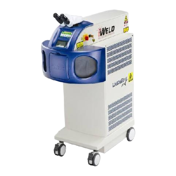
System Description ® ® The LaserStar Workstation™ and the LaserStar Dual Component Welder are movable, stand-alone, single-user operated products that can be used to weld almost all metals and metal alloys quickly, reliably, and precisely. The parts that are to be joined are manually arranged together under visual control and welded together by means of one or more laser pulses. - Page 13 ® LaserStar Workstation Operation & Maintenance Manual 900 Series Ver. 991.6 November 2019 height is correct if the surface of the work piece is in focus under the stereo microscope. Adjusting the energy of the laser pulses can influence the quality of the welding points.
- Page 14 ® LaserStar Workstation Operation & Maintenance Manual 900 Series Ver. 991.6 November 2019 Figure 5 ® (LaserStar Workstation / iWeld Benchtop) Figure 6 ® (LaserStar Workstation / iWeld Professional)
-
Page 15: Welding Chamber / Area
® LaserStar Workstation Operation & Maintenance Manual 900 Series Ver. 991.6 November 2019 The individual functional parts are marked by numbers and explained in the following for Figure 5 & 6. Stereo Microscope The main on/off emergency switch and key-operated switch are located on the right-hand side of the welding chamber/area. -
Page 16: Technical Specifications
Workstation Operation & Maintenance Manual 900 Series Ver. 991.6 November 2019 Technical Specifications ® The modular conception of the LaserStar Workstation facilitates time-saving repairs by changing complete modules (functional units) in case of a failure. The product consists of the following modules assembled in a mobile working table: ... -
Page 17: Cooling
® LaserStar Workstation Operation & Maintenance Manual 900 Series Ver. 991.6 November 2019 Degree of Protection IPX0 L x W x H Benchtop-33”x21”x16” / (84x54x41) cm Professional-33”x21”x43”/(84x54x110) cm Weight Benchtop-125 lbs. / 50 Kg Professional-180 lbs. / 82 Kg Electrical requirements (Reference ID... -
Page 18: Control Circuits
® LaserStar Workstation Operation & Maintenance Manual 900 Series Ver. 991.6 November 2019 Control Microprocessor controller connected to control circuitry for setting of welding parameters Control Circuits for: Cooling water (temperature, level and flow rate) External safety contacts ... - Page 19 ® LaserStar Workstation Operation & Maintenance Manual 900 Series Ver. 991.6 November 2019 View Path and Laser Beam Path (Figure 7) Figure 7 (View Path and Laser Beam Path) The laser beam is fed into the optical path of the microscope via a highly reflective mirror (3).
-
Page 20: Laser Delivery System
® LaserStar Workstation Operation & Maintenance Manual 900 Series Ver. 991.6 November 2019 Miscellaneous Storage of operating parameters Motor-driven beam expander for welding point diameter Removable plate for inserting larger work pieces Accessible joysticks for setting laser parameters ... -
Page 21: Microprocessor Control Unit
® LaserStar Workstation Operation & Maintenance Manual 900 Series Ver. 991.6 November 2019 In closed state, the laser shutter (4) prevents the formation of laser radiation. It will always be closed, for example, if the hand enclosure is opened. -
Page 22: Flashlamp Power Supply, Capacitor Bank, Simmer Supply
® LaserStar Workstation Operation & Maintenance Manual 900 Series Ver. 991.6 November 2019 In case of malfunction of one or more functions, the flashlamp power supply will be shut down and as a consequence, any laser function will be deactivated. -
Page 23: Inert Gas Supply
® LaserStar Workstation Operation & Maintenance Manual 900 Series Ver. 991.6 November 2019 The water is cooled by air circulation. A fan is turned on when the temperature of the cooling water reaches a preset temperature. A flow monitor, a level monitor and an over temperature switch supervise the cooling water circuit and cut off the power supply of the laser lamp in the case of malfunction. - Page 24 ® LaserStar Workstation Operation & Maintenance Manual 900 Series Ver. 991.6 November 2019 (4)-Digital Messaging (2)-Key Switch Touch Screen Display (1)-Mains Switch/ Emergency Off (3)-Controls inside Weld Chamber (Model dependent) Figure 9 (External Controls) (1) Mains Power (Mains) Switch/Emergency Off: This switch turns on or off the line voltage of the product.
-
Page 25: Digital Messaging Touch Screen Display
® LaserStar Workstation Operation & Maintenance Manual 900 Series Ver. 991.6 November 2019 (1)-Gas Flow Control (5) Store (Model Dependent) (2)-Brightness (6) Recall (Model Dependent) (3)-Safety Shutter/ Open (4)-Menu/Joystick Figure 10 (Welding Chamber / Area Controls) (1) Gas Flow Control: This control is used to control the flow of argon (inert) gas. -
Page 26: Electronic Beam Diameter Adjustment
® LaserStar Workstation Operation & Maintenance Manual 900 Series Ver. 991.6 November 2019 The fifth row displays-Home, Recall, Up / Down arrows, ABC, and Save. (Note: When the OK button indicator is green, the welder is ready to weld. The Safety Shutter button is used to open and close the safety shutter and displays the status.) -
Page 27: Remote Interlock Connector
® LaserStar Workstation Operation & Maintenance Manual 900 Series Ver. 991.6 November 2019 Press the pedal switch part way until you feel initial resistance and the inert gas supply is switched “on.” Fully pressing the foot pedal down until it stops triggers laser pulses. The inert gas supply remains “on”... -
Page 28: Safety
The composition of the work piece dictates the vapors or gases generated; therefore, safety precautions are necessary. ® The LaserStar Workstation is designed exclusively for welding metals and metal alloys. To use it for any other purpose or for anything beyond this is to use it improperly. -
Page 29: General Information
Workstation Operation & Maintenance Manual 900 Series Ver. 991.6 November 2019 This symbol draws your attention to operating tips and particularly useful information that will help you use all the functions of your LaserStar to the best effect. ® General Information This laser system is a Class 4 laser. -
Page 30: Fire Hazard
® LaserStar Workstation Operation & Maintenance Manual 900 Series Ver. 991.6 November 2019 When operated without the Workspace Protective Housing or Front Door (model dependant), all persons in the NOHA (Nominal Ocular Hazard Area) must wear appropriate protective laser eye wear (OD>6.5). -
Page 31: Fundamental Safety Information
® LaserStar Workstation Operation & Maintenance Manual 900 Series Ver. 991.6 November 2019 When using solvents or cleaning agents, you must always heed the relevant warnings. Major fires and explosions can quickly result if such containers are accidentally exposed to and destroyed by the intense invisible laser beam. -
Page 32: Personnel Requirements
Dangers when working with the Product ® The LaserStar Workstation is designed according to the state-of-the-art and meets the approved safety regulations. Nevertheless, its use can still endanger life and limb (of the user or third parties) or damage the product or other material assets. -
Page 33: Informal Safety Measures
® LaserStar Workstation Operation & Maintenance Manual 900 Series Ver. 991.6 November 2019 Informal Safety Measures The Operating Instructions must always be kept at the installation site. In addition to the operating instructions, the generally valid regulations, as well as the local ones, on accident prevention and environmental protection, must be complied with, especially the OSHA regulations, ANSI Z136.1-2014, Safe Use of Lasers on accident prevention for laser... -
Page 34: Dangerous Points
Do not make any modifications or additions to the laser product. ® All structural modifications require the written approval of LaserStar Technologies. Immediately replace all parts that are not in perfect condition. Use only original LaserStar Technologies replacement and ®... -
Page 35: Safety Officer
The Laser Safety Officer may receive appropriate training from an approved body (e.g. an institution providing insurance against occupational accidents). The ® Laser Safety Officer may receive training from LaserStar Technologies on the ® proper use of the LaserStar Workstation. -
Page 36: Labeling: Safety And Informational Labels
® LaserStar Workstation Operation & Maintenance Manual 900 Series Ver. 991.6 November 2019 LABELING: Figure (1-9)-Labeling: Housing, Front, Sides and Etc. (Typical) [810-00-019] [810-8001-10] (Note: Read the Manual before Use) (6a) [71-40028] (Note: Required on all welder models) Figure 1 (Mains Power &... - Page 37 ® LaserStar Workstation Operation & Maintenance Manual 900 Series Ver. 991.6 November 2019 (6a) [71-40028] (Note: Required on all models that have a removable access panel without interlocks. Not required on models that have a laser curtain / shield behind the access panel.)
- Page 38 ® LaserStar Workstation Operation & Maintenance Manual 900 Series Ver. 991.6 November 2019 (6a) (8a) [71-40028] [01-40010] (10) [01-40009] [13-40011] (11) [403-XXX] [403-450] [Model Dependent] (13-15) (8a) [479-34XX] [01-40010] AC Voltage Label (Note: Locate (Note: Same VAC Above or Near AC rating as Cert.
- Page 39 ® LaserStar Workstation Operation & Maintenance Manual 900 Series Ver. 991.6 November 2019 (10) [01-40009 Figure 8 (Pump Chamber) (8b) Danger [810-00-016] High Voltage (Equivalent) Remove Power before Servicing Label (12) (10) (01-40012) [01-40009] Figure 9 (iWeld Professional Flashlamp & Cap Charging Power Supplies)
- Page 40 ® LaserStar Workstation Operation & Maintenance Manual 900 Series Ver. 991.6 November 2019 Label Reproductions : (Model Dependent) (Complies with 21 CFR 1040.10 and 1040.11 except for deviations pursuant to Laser Notice No. 50, dated July 26, 2001) (1a or 1b) Aperture Label (model dependent)
- Page 41 ® LaserStar Workstation Operation & Maintenance Manual 900 Series Ver. 991.6 November 2019 (5) Visible Laser Radiation Output and Standards Information Label (Model Dependent) (48-40004) (6a or 6b) Non-Interlocked Protective Housing Label (Model Dependent) (71-40028) (01-40028) (7) Certification and Identification Label (Model Dependent)
- Page 42 ® LaserStar Workstation Operation & Maintenance Manual 900 Series Ver. 991.6 November 2019 (8a) Disconnect Power Plug prior to opening cabinet Label (8b) High Voltage Warning Label: Use caution when opening (01-40010) (810-00-016) (9) The user has to read the manual prior to use label.
- Page 43 ® LaserStar Workstation Operation & Maintenance Manual 900 Series Ver. 991.6 November 2019 (12) Wait 5 Minutes Discharge Label (01-40012) (13) 100 Volts AC Label (Model Dependent) (479-3412) (14) 120 Volts AC Label (Model Dependent) (479-3413) (15) 208-240 Volts AC Label (Model Dependent)
-
Page 44: Iii. Installation
® LaserStar Workstation Operation & Maintenance Manual 900 Series Ver. 991.6 November 2019 III. INSTALLATION This chapter describes the requirements that have to be fulfilled for a faultless operation of the product. Information is also given on the installation, setup and transportation of the product. -
Page 45: Height And Humidity
Carefully remove the packaging, if any. Check the product for possible transport damages. The standard parts of delivery are listed in the following: ® Stand-alone device LaserStar Workstation Viewing system Distilled water (Model dependent) ... -
Page 46: Power Conditions
® LaserStar Workstation Operation & Maintenance Manual 900 Series Ver. 991.6 November 2019 Power Conditions Caution-Check the VAC label & ID label on the rear of the machine and compare with the power conditions at the installation site. AC Voltage Input / Inlet (AC Disconnect) The AC Voltage Input / Disconnect is used to supply AC power to the machine. -
Page 47: External Exhaust System (Optional)
® LaserStar Workstation Operation & Maintenance Manual 900 Series Ver. 991.6 November 2019 The shorting connector is included in the bag in the work chamber/area with the key for the key switch. Refer to Maintenance Section / Fuses and Rear Connections for the location of the remote interlock connector. -
Page 48: Inert Gas
® LaserStar Workstation Operation & Maintenance Manual 900 Series Ver. 991.6 November 2019 Inert Gas For the inert gas (example-argon, nitrogen, etc.) connection, the product is equipped with a quick-acting, compressed-air connector for connecting plastic tubing. Specifications: Inert Gas (Pressure Regulator) ... - Page 49 (hoses & pumps) drained. These activities should only be performed by our LaserStar technicians or authorized skilled persons. The usage of unsuitable materials for drying out the optical components can cause irreparable damages to property.
-
Page 50: Iv. Operation
® LaserStar Workstation Operation & Maintenance Manual 900 Series Ver. 991.6 November 2019 IV. OPERATION Caution - Use of controls or adjustments or performance of procedures other than those specified herein may result in hazardous radiation exposure. If the product is used in a manner not specified by the manufacturer, the protection provided by the equipment may be impaired. - Page 51 ® LaserStar Workstation Operation & Maintenance Manual 900 Series Ver. 991.6 November 2019 “OK” turns green when Safety Shutter system is ready Indicator: to operate Red-Closed Green-Open (Note: Blinks red to green for hand sensor models.) Figure 2 (Digital Messaging Touch Screen Display)
-
Page 52: Adjusting Stereo Microscope
® LaserStar Workstation Operation & Maintenance Manual 900 Series Ver. 991.6 November 2019 Energy Saver / Sleep Mode-This mode reduces the energy consumption of the machine. Press the ON button to return to the main screen. Figure 3 (Energy Saver / Sleep Mode) -
Page 53: Cross-Hair Adjustment
® LaserStar Workstation Operation & Maintenance Manual 900 Series Ver. 991.6 November 2019 Adjust the distance of the two eyepieces that both visual fields (that appear bright) of both eyepieces completely overlap each other, i.e. while observing the test item with relaxed eyes, one single round visual field appears. - Page 54 ® LaserStar Workstation Operation & Maintenance Manual 900 Series Ver. 991.6 November 2019 Figure 4 (Cross Hair Alignment)
-
Page 55: Setting Operation Parameters
® LaserStar Workstation Operation & Maintenance Manual 900 Series Ver. 991.6 November 2019 SETTING OPERATING PARAMETERS Selecting operating parameters is done by using the Digital Message Touch Screen Display or the Joystick(s). (Note-The Safety Shutter Button in conjunction with the Joystick will do special functions.-To be defined later in the manual-model dependent.) - Page 56 ® LaserStar Workstation Operation & Maintenance Manual 900 Series Ver. 991.6 November 2019 this memory location. Gray indicates the weld parameters are not from this memory location. (Note: Memory locations may be loaded with factory defaults. This is model dependent) Memory Location Displays the weld parameter description.
- Page 57 ® LaserStar Workstation Operation & Maintenance Manual 900 Series Ver. 991.6 November 2019 the parameters & description for the selected memory location by pressing the CLEAR button on the screen. ATTENTION: All information in this memory location will be lost. (Note: The parameters &...
- Page 58 ® LaserStar Workstation Operation & Maintenance Manual 900 Series Ver. 991.6 November 2019 on or off) or change the value (i.e.-0.50s). The change is stored by pressing “ENTER”. EXIT button returns to the menu screen. Version: (number) Configuration: >Weld Gas: ON (OFF) (Up/Dn arrow & press ENTER) Pre Weld Gas: 0.00s (Up/Dn arrow &...
- Page 59 ® LaserStar Workstation Operation & Maintenance Manual 900 Series Ver. 991.6 November 2019 ABC Screen (Figure 9 & 10) Press this button to return to the main screen. CLEAR Pressing this button completely clears the memory location description. Pressing these arrows to select the alpha numeric characters.
- Page 60 ® LaserStar Workstation Operation & Maintenance Manual 900 Series Ver. 991.6 November 2019 Volts Figure 8a (Memory Screen) Volts Figure 8b (“Clear Memory 4?” by Pressing CLEAR) Figure 9 (ABC Screen)
- Page 61 ® LaserStar Workstation Operation & Maintenance Manual 900 Series Ver. 991.6 November 2019 Figure 10 (123 Screen) Figure 11 (Recall Screen) Figure 12 (Memory Recalled Screen)
-
Page 62: Storing Operating Parameters
JOYSTICK OPERATION (Single Joystick Panel) You can set all the operating parameters (except pulse suppression) using the joystick in the welding chamber area. This panel has Save & Recall buttons. (Reference Section I / The LaserStar ® Workstation / Control Elements in Welding Chamber / Area / Single Joystick.). - Page 63 ® LaserStar Workstation Operation & Maintenance Manual 900 Series Ver. 991.6 November 2019 so that you can subsequently work with the same tried-and-tested operating data. (Note: Reference Appendix Section for details on Pulse Shaping.) In order to identify the different memory locations more easily, you can assign them user definable texts.
- Page 64 ® LaserStar Workstation Operation & Maintenance Manual 900 Series Ver. 991.6 November 2019 ATTENTION: When storing parameters in a selected memory location, the beam expander offset and the voltage adjustment values displayed in the “Menu” at that time will be stored in that memory location.
-
Page 65: Recalling Stored Parameters
® LaserStar Workstation Operation & Maintenance Manual 900 Series Ver. 991.6 November 2019 RECALLING STORED PARAMETERS You can use the joystick(s) & memory recall button in the welding chamber area or you can use the Digital Messaging Touch Screen Display to recall operating parameters that you have previously stored in a specific memory location (see the section entitled STORING OPERATING PARAMETERS). - Page 66 ® LaserStar Workstation Operation & Maintenance Manual 900 Series Ver. 991.6 November 2019 Press the foot pedal (Note: The weld >Fire the Laser parameters can be optimized by using the Digital Messaging Touch Screen Display or the Joystick(s).) (*)-Do not position your hands in or under the crosshair.
-
Page 67: Resetting Pulse Count
® LaserStar Workstation Operation & Maintenance Manual 900 Series Ver. 991.6 November 2019 > If several laser pulses are to be released one after the other, in single-pulse mode, the pedal switch must be slightly released and then fully depressed again. In continuous... -
Page 68: Status Indications
Digital Messaging Touch Screen Display. If the indicator is green in the “OK” button, the system is ready to weld. ® In the LaserStar Workstation, the micro controller monitors the conditions for pulse release on the basis of the following criteria: ... -
Page 69: Pulse Suppression
/ Factory Installed / Appendix B) The restricted access option is used to prevent unauthorized changes to the weld parameters. This option should be installed in the welder system at LaserStar prior to shipment. The user can then enable or disable the restricted access... -
Page 70: Maintenance
The service personnel must verify the product is in a safe state after maintenance or service is completed. Use only LaserStar approved parts and accessories. NEVER WORK ALONE when performing service or maintenance activities. A second person, who should be at least familiar with the risks posed by laser radiation and high voltages, should always be present during service and maintenance activities. -
Page 71: System Maintenance Alert Reminders And Resetting
® LaserStar Workstation Operation & Maintenance Manual 900 Series Ver. 991.6 November 2019 HIGH VOLTAGE This laser device complies with all generally recognized technical standards and regulations. This includes OSHA, EC, EN, DIN and VDE standards. This laser is ignited and operated using dangerous high voltage (>1 kV), so special care has to be taken when working on... - Page 72 ® LaserStar Workstation Operation & Maintenance Manual 900 Series Ver. 991.6 November 2019 Digital Messaging Touch Screen Display Maintenance Alerts Table 1 (Note: DI refers to Distilled Water)
-
Page 73: Daily
3. The Protective Disk, located inside the welding chamber/area, should be unscrewed from the focusing lens and cleaned with a lens cleaning ® solution. The preferred cleaning solution is LaserStar p/n 810-2353. The ® preferred wipes are LaserStar p/n 810-2356 (qty 1) or 810-2354 (qty 90). -
Page 74: Quarterly, Semi-Annual, Yearly
Compare the spot to the samples provided at installation. If not ® similar, contact LaserStar Technical Service Department. Quarterly (Three months) Semi-Annually (Six months) 1. Change the distilled water every 3 months. -
Page 75: Focus Lens Protective Disk Replacement
® LaserStar Workstation Operation & Maintenance Manual 900 Series Ver. 991.6 November 2019 Replacement of the Focus Lens Protective Glass Disk Switch off the laser, turn main switch to "0.” Wait five minutes for lights to cool. Insert hands in hand openings. -
Page 76: Filter Replacement, Welding Chamber/Area
® LaserStar Workstation Operation & Maintenance Manual 900 Series Ver. 991.6 November 2019 DO NOT SCRATCH THE SPLASH PROTECTIVE WINDOW Put the laser protective window with the labels showing up onto the splash protective window. Put both windows from inside into the assigned openings of the cover. -
Page 77: Digital Messaging Touch Screen Display Cleaning Instructions
® LaserStar Workstation Operation & Maintenance Manual 900 Series Ver. 991.6 November 2019 Digital Messaging Touch Screen Display Cleaning Instructions It's important to realize the touch panel is sensitive to chemicals, much as is a pair of glasses with plastic lenses (usually polycarbonate with a glare reduction coating). -
Page 78: Vi. Troubleshooting
FAULT CLEARANCE, please immediately contact the service department of ® LaserStar Technologies. Service activities may only be performed by service technicians of LaserStar Technologies, properly ® trained personnel, or LaserStar supervised personnel. ® LaserStar Technologies Corporation ® One Industrial Court Riverside, Rhode Island 02915 USA Tel: 401-438-1500 E-mail: service@laserstar.net... -
Page 79: System Messages
Workstation Operation & Maintenance Manual 900 Series Ver. 991.6 November 2019 In case of any malfunction of the device that cannot be eliminated by one of the actions described in the sections MAINTENANCE, SYSTEM MESSAGES, or ALARMS, please immediately contact the service department of LaserStar. SYSTEM MESSAGES POSSIBLE REASON... - Page 80 ® LaserStar Workstation Operation & Maintenance Manual 900 Series Ver. 991.6 November 2019 SYSTEM ALARMS** POSSIBLE REASON** Simmer Supply Off Check and (or) change Flashlamp. (Reference Service Section / Simmer for details on lamp status) Water Flow Low Prime the water pump by opening the petcock or equivalent located near the water bottle.
- Page 81 ® LaserStar Workstation Operation & Maintenance Manual 900 Series Ver. 991.6 November 2019 ALARMS Table 1...
-
Page 82: Vii. Parts And Accessories List
® LaserStar Workstation Operation & Maintenance Manual 900 Series Ver. 991.6 November 2019 VII. PARTS AND ACCESSORIES LIST Description Catalog Number Operation & Maintenance Manual 87-99990-991 File Operation & Maintenance Manual 87-99991-991 on a USB Flash Drive iWeld Laser Pump Chamber... - Page 83 ® LaserStar Workstation Operation & Maintenance Manual 900 Series Ver. 991.6 November 2019 Flow Plate 31-10047 Focus Lens Protective Disk 01-10112 Fuse 10A 250VAC SB 5x20 405-4320-100 Halogen Lamp 405-2460-114 Laser Reflector (Ceramic) 31-10045 Laser Rod Replacement Kit 187-00-2015 includes O-ring Kit...
-
Page 84: Viii. Warranty Original Equipment
Any unauthorized use, misuse, neglect, modification, or use with non- LaserStar approved or authorized accessories will make these warranties null and void. Under no circumstance will LaserStar have any liability for loss of use or for any indirect or consequential damages. Satisfaction of this warranty, consistent with other provisions... - Page 85 Unless such authority has been granted, shipment will be refused. Any and all transportation expenses associated with the evaluation or repair of LaserStar's laser machines is the sole expense of the Buyer. Authority for return of equipment for repair MUST have a RMA or CRA number assigned and clearly marked on the exterior of the container.
-
Page 86: Ix. Service
Power on (Unplug the machine or switch off the circuit breaker and wait 5 minutes before servicing.) LaserStar Technologies is not responsible for machine damage caused by personnel that have not been properly trained or supervised. In case of any malfunction of the product that cannot be eliminated by one of the... -
Page 87: Service A: Professional Series Distilled Water Cooling System
® LaserStar Workstation Operation & Maintenance Manual 900 Series Ver. 991.6 November 2019 Service A: Professional Series Distilled Water Cooling System Tools-Supplied or Required: Phillips Screw Driver #2 Metric Hex Key Wrench Set (Metric 1.5 to 6 mm set) ... - Page 88 Off. Leave the system off for 5 minutes and repeat this step. ® c. If not okay, please contact LaserStar Service.) 11. Run the pump until there are no more air bubbles visible in all of the hose lines (Note: Normally this will take 10 to 15 minutes.)
- Page 89 ® LaserStar Workstation Operation & Maintenance Manual 900 Series Ver. 991.6 November 2019 B. Refilling / Topping Off the Distilled Water Bottle 1. Make sure the laser is “Off”, turn the Key-switch to “O” / “Off”, turn Mains Power switch to "O” / “Off”.
- Page 90 If the pump starts to squeal / strange sounds immediately turn the system “Off”. Please try again after 15 minutes and repeat this step. ® c. If not okay, please contact LaserStar Field Service.) Attention: Check for leaks at the water bottle top hose disconnect fitting.
- Page 91 ® LaserStar Workstation Operation & Maintenance Manual 900 Series Ver. 991.6 November 2019 17. Run the pump until there are no more air bubbles visible in all the hoses.. (Note: Normally this will take 10 to 15 minutes.) 18. Turn “Off” the Mains Power Switch and wait for 5 minutes.
- Page 92 ® LaserStar Workstation Operation & Maintenance Manual 900 Series Ver. 991.6 November 2019 10. Connect the female air garden hose assembly to the front pump chamber male cooling hose fitting / (1) on the pump chamber (Figure 5); open the by-pass pinch valve (Figure 1);...
- Page 93 ® LaserStar Workstation Operation & Maintenance Manual 900 Series Ver. 991.6 November 2019 (Note: Distilled water bottle filling can be done from By-pass pinch the left side of the valve/(normally machine by using closed) the fill / by-pass hole or removing the water bottle cap.)
- Page 94 ® LaserStar Workstation Operation & Maintenance Manual 900 Series Ver. 991.6 November 2019 Top water bottle disconnect fitting Bottom water bottle Water bottle disconnect fitting strap Water bottle level sensor connector Figure 3 (Water Bottle Bottom Disconnect Fitting & Level Sensor Connector)
- Page 95 ® LaserStar Workstation Operation & Maintenance Manual 900 Series Ver. 991.6 November 2019 Pump Chamber (3)-Rear pump (1)-Front pump chamber male chamber male cooling Hose cooling hose fitting fitting (4)-Rear (2)-Front cooling hose cooling hose female fitting female fitting (Figure 5)
-
Page 96: Service B: Benchtop Series Distilled Water Cooling System
® LaserStar Workstation Operation & Maintenance Manual 900 Series Ver. 991.6 November 2019 Service B: Benchtop Series Distilled Water Cooling System Tools-Supplied or Required: Phillips Screw Driver #2 Metric Hex Key Wrench Set (Metric 1.5 to 6 mm set) ... - Page 97 If the water level in the bottle has not gone down in 10 to 20 seconds, immediately turn “Off” the machine. d. Wait for 5 minutes and try again. ® e. If not okay, please contact LaserStar Service.) (Attention: If the pump is still making strange sounds / squealing after completing step 15, turn OFF / “0”...
- Page 98 ® LaserStar Workstation Operation & Maintenance Manual 900 Series Ver. 991.6 November 2019 19. Turn OFF / “0” the Mains Power switch and unplug the AC cord. 20. Install the blue filter media. Connect the ground wire to the side panel and install the panel.
- Page 99 ® LaserStar Workstation Operation & Maintenance Manual 900 Series Ver. 991.6 November 2019 D. Removing the Distilled Water from the Machine for Storage or Transport (Note: Reference the procedure / steps described in section A / “Initial Filling of the laser Welding System with Distilled Water” with the following additional steps.)
- Page 100 ® LaserStar Workstation Operation & Maintenance Manual 900 Series Ver. 991.6 November 2019 Top cover screws (2) Note: The “Max (Filter In)” line is located on the side of the bottle inside the enclosure. Min (Filter In) When the water reaches the “Min...
- Page 101 ® LaserStar Workstation Operation & Maintenance Manual 900 Series Ver. 991.6 November 2019 screw screw screw screw Remove the 6 screws securing the side panel and slide the panel back screw screw Figure 3 (Top Cover Removed & Left Side Cover Fasteners being Removed)
- Page 102 ® LaserStar Workstation Operation & Maintenance Manual 900 Series Ver. 991.6 November 2019 Distilled Water Bottle Assembly Max Line (Filter Out) Figure 5 (Distilled Water Bottle Located in Rear of Enclosure) Hose Clamp (463-089) Remove Distilled Water Bottle Twist Figure 6...
- Page 103 ® LaserStar Workstation Operation & Maintenance Manual 900 Series Ver. 991.6 November 2019 Lift the filter assembly out of the bottle and place in clean Hose Clamp container (Note: (463-089) Distilled Water may leak out.) (Attention: Please do Distilled Water...
- Page 104 ® LaserStar Workstation Operation & Maintenance Manual 900 Series Ver. 991.6 November 2019 Re-install the Distilled Water Filter Assembly & screw on the Twist Cap. Twist Cap should be tightened by hand. Distilled Water Figure 9 (Distilled Water Bottle Filter & Cap Installed)
-
Page 105: Service C: Flashlamp Replacement
6” spout (McMaster-Carr-#7656K3) Clean Container for the Distilled Water Distilled Water Clean Room Vinyl/PVC Gloves (Powder-Free/DEHP & DOP Free) Lint Free Cloth or preferred LaserStar ® P/N 810-2356 (quantity 1) or 810- 2354 (quantity 90) ... - Page 106 ® LaserStar Workstation Operation & Maintenance Manual 900 Series Ver. 991.6 November 2019 3. Remove machine top cover by removing the screws located on the rear of the cover as shown in (Figure 1). Carefully slide the cover back and remove the ground wire/green with a yellow stripe.
- Page 107 “iWeld Laser Pump Chamber Repair Instructions” / (87-99990-187 are available on the LaserStar Customers’ Website. (Note: Please contact the LaserStar Service Department for repair guidance on Laser Pump Chamber Assembly / 187-00-1001 components. Components / kits include flashlamps, laser rod assembly, flow plate, O-rings, etc.
- Page 108 ® LaserStar Workstation Operation & Maintenance Manual 900 Series Ver. 991.6 November 2019 Step 2 / Figure 2a, 2b (Benchtop) & 2c (Professional) (Disconnect flashlamp wires & trigger transformer connector.) Disconnect Red (L+) and Black (L-) flashlamp wires using 3/16” slotted...
- Page 109 ® LaserStar Workstation Operation & Maintenance Manual 900 Series Ver. 991.6 November 2019 Step 3 / Figure 3 (Place paper towels below the two hose / tubing fittings. Attention: Do not disconnect either hose fitting at this time.) Front hose...
- Page 110 ® LaserStar Workstation Operation & Maintenance Manual 900 Series Ver. 991.6 November 2019 Step 5 / Figure 5 (Carefully lift up the rear of the chamber and slowly disconnect the rear hose fitting. Let the pump chamber drain for ~10 seconds to allow the remaining water in the pump chamber to drain out;...
- Page 111 ® LaserStar Workstation Operation & Maintenance Manual 900 Series Ver. 991.6 November 2019 Step 7 / Figure 7 (Rotate pump chamber so that the black wire is facing outward and remove end cap screws and end cap using a M2.5 Hex Key Wrench.)
- Page 112 ® LaserStar Workstation Operation & Maintenance Manual 900 Series Ver. 991.6 November 2019 WEAR EYE PROTECTION AND PROTECTIVE GLOVES! DO NOT HANDLE THE FLASHLAMP ASSEMBLY OR LASER ROD ASSEMBLY UNLESS YOU ARE WEARING LAB QUALITY GLOVES Step 9 / Figure 9 (Rotate pump chamber so that the black wire end is on the right;...
- Page 113 ® LaserStar Workstation Operation & Maintenance Manual 900 Series Ver. 991.6 November 2019 Step 11 / Figure 11 (Install a new O-ring on both ends of the flashlamp assembly.) O-ring Figure 11 (New O-ring Installed) Step 12 / Figure 12 (Install end caps with screws on both ends of the Pump Attention: Do not tighten screws @ this time.)
- Page 114 ® LaserStar Workstation Operation & Maintenance Manual 900 Series Ver. 991.6 November 2019 Step 13 / Figure 13 (Position the flashlamp assembly such that the each end of the flashlamp (plastic body/insulator) extends equally ( ) on both ends of the pump chamber.)
- Page 115 ® LaserStar Workstation Operation & Maintenance Manual 900 Series Ver. 991.6 November 2019 Step 15 / Figure 15 (Carefully place the pump chamber back into the laser rail. Attention: Do not bump the rear mirror assembly.) Carefully place the Screw...
- Page 116 ® LaserStar Workstation Operation & Maintenance Manual 900 Series Ver. 991.6 November 2019 Step 17 / Figure 17 (Connect the red and black flashlamp wires to the flashlamp rail connector as shown in Figure 18.) Flashlamp rail connector Cable clamp...
- Page 117 ® LaserStar Workstation Operation & Maintenance Manual 900 Series Ver. 991.6 November 2019 ATTENTION: Verify the (L+) / RED wire and (L-) / BLACK wire are connected correctly. A lamp installed with reverse polarity will age after just a few...
- Page 118 Front hose Rear hose fitting fitting Figure 21 (Connect & Tighten Both Hose Fittings) ATTENTION: Do not start the system if any water gets on the electronics. Let system dry for 24 hours. If not dry, call LaserStar Service for instructions.
- Page 119 ® LaserStar Workstation Operation & Maintenance Manual 900 Series Ver. 991.6 November 2019 Step 22-Fill the water bottle and bleed the system per Service A / Professional or Service B / Benchtop ATTENTION: While bleeding the system, verify that there are no Pump Chamber leaks around the flashlamp O-ring seals and pump chamber hose connections.
-
Page 120: Service D: Simmer Supply
® LaserStar Workstation Operation & Maintenance Manual 900 Series Ver. 991.6 November 2019 Service D: Simmer Supply (Note: Reference Service section / Major System Components for the simmer location for the specific machine model / series location.) The following Led Indicators can be used to indicate the status of the AC Simmer Board Assembly and the status of the Flashlamp. -
Page 121: Service E: Cap Charging Supplies
® LaserStar Workstation Operation & Maintenance Manual 900 Series Ver. 991.6 November 2019 Service E: Cap Charging Supplies There are four (4) basic configurations of the Cap Charging Supplies: Note: If the indicator is not green, the unit is not powered up or... -
Page 122: Service F: Memory Battery Replacement / Control Board
A replacement battery can be purchased ® ® from LaserStar Technologies Corporation. The LaserStar part number is 405- 3900-001. (Note: A replacement battery may be purchased at a reputable retailer. Make sure the battery has the same part number / specification.) 1. - Page 123 ® LaserStar Workstation Operation & Maintenance Manual 900 Series Ver. 991.6 November 2019 Carefully slide the battery Memory Back Up Battery “Replace the Battery with out in the direction of the arrow. Reference Figure the same type of Battery” 1b (Note: Take care not to over bend the battery retaining clip.)
-
Page 124: Service G: Benchtop Fuse Replacement, Rear System Description And Connections
(VAC) Standards Information Label Figure 1 (Rear View-Fuses) (Note: Refer to Label Reproductions Section for detail label description.) Table 1 Fuse # LaserStar© Part Amperage/Voltage Type 120 & 230 Volt AC Version 1 & 2 405-4320-100 10.0A/250VAC/Time- Mains Power Lag/5 X20mm Cartridge... - Page 125 ® LaserStar Workstation Operation & Maintenance Manual 900 Series Ver. 991.6 November 2019 Connections-Rear (Figure 2) Exhaust Output Argon Gas (Inert Gas) (*)AC Voltage Input/Disconnect (Reference ID Label for Specific Voltage, Remote Interlock Current & Hz) Connector Receptacle [Note-(**)] Air or Gas...
-
Page 126: Service H: Professional Fuse Replacement, Rear System Description And
® LaserStar Workstation Operation & Maintenance Manual 900 Series Ver. 991.6 November 2019 Service H: Professional-Fuse Replacement, Rear System Description & Connections Rear System Description & Connections (Figure 1) (Note: Refer to Label Reproductions for detail label description.) (8a)-Disconnect Power Plug Prior to... - Page 127 (*)Caution-Check the VAC label & ID label on the rear of the machine and compare with the power conditions at the installation site. Table 1 Fuse # LaserStar© Part Amperage/Voltage Type 120 & 230 Volt AC Version 1 & 2 405-4320-100 10.0A/250VAC/Time-...
- Page 128 ® LaserStar Workstation Operation & Maintenance Manual 900 Series Ver. 991.6 November 2019 Other External Connections Argon Gas (Inert Air Input Gas) Input Connector Connector (Optional) EZ-Link USB Connector (Software Optional) Remote Interlock Video Out Connector Receptacle Connector [Note-(**)] (Optional) Figure 3 (Air, Argon Gas, EZ-Link, Remote Interlock &...
-
Page 129: Service I: Benchtop Major Internal System Components
® LaserStar Workstation Operation & Maintenance Manual 900 Series Ver. 991.6 November 2019 Service I: Benchtop / Major Internal System Components Power Supplies AC Line Filter Safety Shutter Flashlamp Chamber AC Simmer Supply behind 24VDC Power Supply Power Supply, 24VDC... - Page 130 ® LaserStar Workstation Operation & Maintenance Manual 900 Series Ver. 991.6 November 2019 Laser Rail Rear Mirror Flashlamp Trigger Safety Front Mirror Assembly Chamber Transformer Shutter Assembly Electronic Beam Expander Safety Shutter Control Board Figure 3 (Laser Rail-Typical)
-
Page 131: Service J: Professional Major Internal System Components
® LaserStar Workstation Operation & Maintenance Manual 900 Series Ver. 991.6 November 2019 Service J: Professional-Major Internal System Components Power, Control & Distilled Water Bottle Control Board Simmer Supply Rabbit Core Module Memory Back Up Battery “Replace the Battery with the same type of Battery”... - Page 132 ® LaserStar Workstation Operation & Maintenance Manual 900 Series Ver. 991.6 November 2019 Power Supplies & Fan Controller Light Dimmer Board Power Supply- 48VDC (Heat Exchanger Fan) AC Line Filter Controller Board Power Supply- 24VDC Ground Bus Figure 2 (Power Supplies & Fan Controller-Left Side)
-
Page 133: Service K: Brackets For Benchtop & Professional Series Installation
® LaserStar Workstation Operation & Maintenance Manual 900 Series Ver. 991.6 November 2019 Service K: Brackets for iWeld Benchtop & Professional Series for Floor or Wall Installation (model dependent) (Note: Bracket screws / 5mmx12mm / LST#88-56881-512 are installed in all iWeld models prior to shipment.) - Page 134 ® LaserStar Workstation Operation & Maintenance Manual 900 Series Ver. 991.6 November 2019...
-
Page 135: Appendixes
® LaserStar Workstation Operation & Maintenance Manual 900 Series Ver. 991.6 November 2019 X. APPENDIXES... - Page 136 ® LaserStar Workstation Operation & Maintenance Manual 900 Series Ver. 991.6 November 2019...
-
Page 137: Appendix A: Single Joystick Detail Operation
® LaserStar Workstation Operation & Maintenance Manual 900 Series Ver. 991.6 November 2019 Appendix A: Single Joystick Detail Operation (990 / 980 / 970 / 960 / 1000 / 1200 / 1900) You can set the operating parameters using the Joystick in the welding chamber/area (Figure 30). - Page 138 ® LaserStar Workstation Operation & Maintenance Manual 900 Series Ver. 991.6 November 2019 STORING OPERATING PARAMETERS (Joystick) The product's controller has memory locations in which sets of operating parameters (each optimized for specific applications or materials, for example) can be stored so that you can subsequently work with the same tried-and-tested operating data.
- Page 139 ® LaserStar Workstation Operation & Maintenance Manual 900 Series Ver. 991.6 November 2019 o To select a new memory number move J left until memory number is blinking o Move J up or down to select a new memory number...
- Page 140 ® LaserStar Workstation Operation & Maintenance Manual 900 Series Ver. 991.6 November 2019 Laser SHTR closed III* Press “R” (1X) 250V 1.5mS 0Hz 0B 0.3mm* Recall memory 28? 28 III* Move “J” Left (2X) 250V 1.5mS 0Hz 0B 0.3mm* 24 III* Move “J”...
- Page 141 ® LaserStar Workstation Operation & Maintenance Manual 900 Series Ver. 991.6 November 2019 The following is an example: Example Action Display Display Information Line Display Updates 250V 1.5mS 0Hz 0B 0.3mm* Laser SHTR closed III* Press “R” (1X) 250V 1.5mS 0Hz 0B 0.3mm*...
- Page 142 ® LaserStar Workstation Operation & Maintenance Manual 900 Series Ver. 991.6 November 2019 Move “J” Right/RT (1X) 24IIIExampl_ UpDn=Sel RT=Accept Move “J” Up or Down to “e” 24IIIExample UpDn=Sel RT=Accept Move “J” Right/RT (1X) 24IIIExample_ UpDn=Sel RT=Accept Move “J” Left/Exit (1X) 200V 1.0mS 3Hz 0B 0.2mm*...
-
Page 143: Appendix B: Restricted Access / Password Option (Factory Installed)
(Option / Factory Installed) Operation: The restricted access feature is used to prevent unauthorized changes to the weld parameters. This feature should be set up at LaserStar per customer request prior to shipping the welder system. The customer can then enable or disable the restricted access feature / password protection at any time. - Page 144 ® LaserStar Workstation Operation & Maintenance Manual 900 Series Ver. 991.6 November 2019 Press the “UP” arrow to set the first number (Note: DN can be used to decrease the number) Press “MENU” on the Password Screen and a (*) will be loaded into the first digit and the second digit “0”...
- Page 145 ® LaserStar Workstation Operation & Maintenance Manual 900 Series Ver. 991.6 November 2019 Figure 3 (Up or Down Arrow>NO or YES) Figure 4 (YES>ON>EXIT>EXIT) Figure 5 (MEM)
- Page 146 ® LaserStar Workstation Operation & Maintenance Manual 900 Series Ver. 991.6 November 2019 JOULES .500 Figure 6 (MENU>UP or DN ARROW>”4”) JOULES .500 Figure 7 (MENU>UP or DN ARROW>”3”) JOULES .500 Figure 8 (MENU>UP/DN>”8”>MENU)
-
Page 147: Appendix C: Yearly Maintenance Chart / Checklist
® LaserStar Workstation Operation & Maintenance Manual 900 Series Ver. 991.6 November 2019 Appendix C: Yearly Maintenance Chart / Checklist... - Page 148 ® LaserStar Workstation Operation & Maintenance Manual 900 Series Ver. 991.6 November 2019...
- Page 149 Daily: Wipe Laser / Wipe chamber / Clean protective disc (w) = Water change (w&f) = Water & Filter change Month 1 Month 2 Month 3 Month 4 Month 5 Month 6 Month 7 Month 8 Month 9 Month 10 Month 11 Month 12 7 Weekly 7 Weekly 7 Weekly...
- Page 151 ® LaserStar Workstation Operation & Maintenance Manual 900 Series Ver. 991.6 November 2019 Appendix D: Pulse Performance Profile Technology...
- Page 152 ® LaserStar Workstation Operation & Maintenance Manual 900 Series Ver. 991.6 November 2019...
- Page 161 RECOMMENDED PRE-PROGRAMMED PARAMETER SETTINGS 40 JOULE iWELD LASER SYSTEM NOTE: Beam diameter based on number of clicks open to the right. WHITE GOLD POROSITY PLATINUM POROSITY 205V 6.0MS 3.0HZ 3 CLICKS 250 V 4.0MS 3.0HZ 3 CLICKS WHITE GOLD RE-TIP PLATINUM RE-TIP 206V 4.5 MS 3.0HZ 6 CLICKS 248 V 3.9MS 3.0HZ 4 CLICKS...
- Page 162 RECOMMENDED PRE-PROGRAMMED PARAMETER SETTINGS 40 & 60 JOULE iWELD LASER SYSTEM WITH P3 WHITE GOLD POROSITY PLATINUM POROSITY 190V 3.5MS 3.0HZ 0.50MM 234V 3.0MS 2.0HZ 0.60MM Ramp Up Profi le Basic Profi le WHITE GOLD RE-TIP PLATINUM RE-TIP 195V 3.5MS 3.0HZ 0.50MM 225V 3.0MS 3.0HZ 0.60MM Ramp Up Profi...
- Page 163 RECOMMENDED PRE-PROGRAMMED PARAMETER SETTINGS 80 JOULE iWELD LASER SYSTEM WITH P3 WHITE GOLD POROSITY PLATINUM POROSITY 190V 3.7MS 3.0HZ 0.70MM 213V 2.5MS 2.0HZ 0.80MM Ramp Up Profi le Basic Profi le WHITE GOLD RE-TIP PLATINUM RE-TIP 193V 3.3MS 3.0HZ 0.65MM 215V 2.5MS 2.0HZ 0.80MM Ramp Up Profi...
- Page 164 RECOMMENDED PRE-PROGRAMMED PARAMETER SETTINGS 100 JOULE iWELD LASER SYSTEM WITH P3 WHITE GOLD POROSITY PLATINUM POROSITY 185V 3.7MS 3.0HZ 0.70MM 208V 2.5MS 2.0HZ 0.80MM Ramp Up Profi le Basic Profi le WHITE GOLD RE-TIP PLATINUM RE-TIP 188V 3.3MS 3.0HZ 0.65MM 210V 2.5MS 2.0HZ 0.80MM Ramp Up Profi...
- Page 165 280V 4.0MS 2.0HZ 0.30MM Ramp Down Profi le NOTE: The above parameter combinations are suggested starting points for 80 Joule LaserStar Welding Systems (7000 Series) and are subject to change based on fl ashlamp age and the alloy’s surface condition.
- Page 166 310V 6.5MS 1.5HZ 0.60MM Ramp Down Profi le NOTE: The above parameter combinations are suggested starting points for 80 Joule LaserStar Welding Systems (7000 Series) with Soft-Touch and are subject to change based on fl ashlamp age and the alloy’s surface condition.
- Page 167 280V 4.0MS 2.0HZ 0.30MM Ramp Down Profi le NOTE: The above parameter combinations are suggested starting points for 100 Joule LaserStar Welding Systems (7000 Series) and are subject to change based on fl ashlamp age and the alloy’s surface condition.
- Page 168 330V 4.6MS 1.5HZ 0.50MM Ramp Down Profi le NOTE: The above parameter combinations are suggested starting points for 100 Joule LaserStar Welding Systems (7000 Series) with Soft-Touch and are subject to change based on fl ashlamp age and the alloy’s surface condition.
- Page 169 Ramp Down Profi le NOTE: The above parameter combinations are suggested starting points for 100 Joule LaserStar Welding Systems (7000 Series) with Soft-Touch and 3X Beam Expander and are subject to change based on fl ashlamp age and the alloy’s surface condition.
- Page 170 300V 4.5MS 1.5HZ 0.50MM Ramp Down Profi le NOTE: The above parameter combinations are suggested starting points for 120 Joule LaserStar Welding Systems (7000 Series) and are subject to change based on fl ashlamp age and the alloy’s surface condition.
- Page 171 380V 7.0MS 1.5HZ 0.30MM Ramp Down Profi le NOTE: The above parameter combinations are suggested starting points for 120 Joule LaserStar Welding Systems (7000 Series) with Soft-Touch and are subject to change based on fl ashlamp age and the alloy’s surface condition.
- Page 172 200V 2.0MS 0.0HZ 0.75MM Ramp Down Profi le Basic Profi le NOTE: The above parameter combinations are suggested starting points for 150 Joule LaserStar Welding Systems (7000 Series) and are subject to change based on fl ashlamp age and the alloy’s surface condition.
Need help?
Do you have a question about the iWeld 900 Series and is the answer not in the manual?
Questions and answers
Touchscreen will not come on. lights in chamber are working
The touchscreen may not be working because it is sensitive to chemicals, similar to plastic lenses with a glare reduction coating. If it has been cleaned with improper chemicals, it may be damaged. Additionally, there is no mention of a direct connection between the chamber lights and touchscreen functionality, so the issue could be unrelated to power. Cleaning the touchscreen with a suitable cleaning kit may help restore functionality if it is only dirty rather than damaged.
This answer is automatically generated
machine is saying simmer supply off can we replace the fuse
We have LaserStar iWeld 900 Series and got attached error. Please advise what a protective disc looks like and is this error message cause any issues if we click 'Done' and continue with welding? Can this error cause holes in the weld?