Table of Contents
Advertisement
Quick Links
Advertisement
Chapters
Table of Contents

Summary of Contents for LM Trac 287
- Page 1 LM 287 User Manual – 30.10.2023 User manual...
- Page 2 LM 287 User Manual – 30.10.2023...
-
Page 3: Foreword
For the above reason, it is possible that the machine does not correspond in full to the information provided in this manual. Your LM Trac dealer can provide you with the latest data, and you can get a new updated version of the manual if necessary. -
Page 4: Machine Specifications And Type Plate
LM 287 User Manual – 30.10.2023 1.1 Machine specifications and type plate Write the data in the rows below: Owner: ____________________________________ __________________________ Address: ____________________________________ Tel.: ______________________ Main machine: Serial number: _______________________ Model:____________________ Engine: Serial number:________________________ Model:____________________ Dealer: ____________________________________ Tel.: ______________________ Spare parts provider: ______________________________ Tel.: ______________________... - Page 5 LM 287 User Manual – 30.10.2023 NOTES:...
-
Page 6: User Manual Structure
6 Maintenance 7 Technical specifications The LM Trac machine embodies the latest technology and its operation and maintenance also set requirements for the person operator and maintenance engineer. By reading and understanding the information contained in this manual, you will ensure the safe and technically correct operation and maintenance of this machine. -
Page 7: Table Of Contents
LM 287 User Manual – 30.10.2023 Table of contents Foreword Machine specifications and type plate ................4 User manual structure ....................6 Safety and environmental protection ................6 Structural changes ......................6 Liability for errors and warranty ..................6 SAFETY Markings and symbols .................... - Page 8 Fire Safety........................61 Recycling instructions and environmental consideration ..........61 6.6.1 Hazardous waste generated during maintenance ..........61 6.6.2 Disabling the LM Trac multipurpose compact tractor .......... 62 Periodic maintenance ....................63 6.7.1 Periodic maintenance interval table ..............63 6.7.2 Maintenance item locations .................
- Page 9 LM 287 User Manual – 30.10.2023 6.13 Maintenance every 500 operating hours ..............82 6.13.1 Engine oil change and oil filter replacement (25) ..........82 6.13.2 Primary fuel filter element replacement (26) ............83 6.13.3 Hydraulic oil return filter replacement (27) ............84 6.13.4...
-
Page 10: Safety
In the case of a failure that you cannot resolve and eliminate, please contact LM Trac Service. Stop working immediately if there is the slightest chance of the failure causing a risk of injury or damage to the machine. -
Page 11: During Operation
LM 287 User Manual – 30.10.2023 2.2.2 During operation • Enter and exit the machine in a safe way. Always use the handgrips and steps. Never grab the controls when entering the machine. Never jump up to or down from the machine. -
Page 12: During Maintenance
LM 287 User Manual – 30.10.2023 2.3 During maintenance • Park the machine on hard level terrain, lower all tools and stop the engine. • Always keep first aid equipment and a fire extinguisher near the maintenance area. • If you are working underneath a raised bonnet/platform body, support it mechanically in the upper position. -
Page 13: Machine Structure
The machine is equipped with rear-wheel steering. Efficient use of the LM Trac 287 machine requires that the driver understands the principle of the machine's driving automation. -
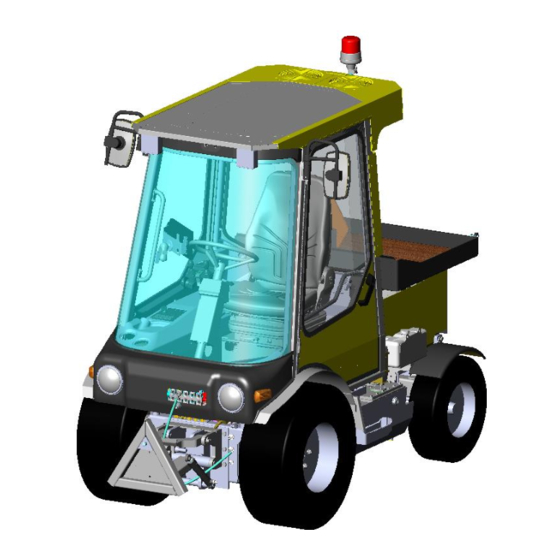
Page 14: Main Components And External Equipment
LM 287 User Manual – 30.10.2023 3.1 Main components and external equipment Figure 6 1. Cabin 2. Front working lights (2 pcs) 3. Side mirrors 4. Flashing beacon 5. Rear working light (1 pc) 6. Bonnet 7. Engine 8. Service hatch 9. - Page 15 LM 287 User Manual – 30.10.2023 Figure 7 1. Coolant expansion tank 2. Hydraulic oil tank 3. Hydraulic oil sight glass 4. Windscreen washing fluid tank 5. Service hatch 6. Trailer hitch/Rear tool attachment (accessory) 7. Rear tool power take-out 8.
-
Page 16: Front Lifter And Quick Coupling Device
LM 287 User Manual – 30.10.2023 3.1.1 Front lifter and quick coupling device Depending on your choice, your machine is equipped with the A frame version A or rotating version B, or the three‐point attachment device C. Figure 8 1. Lifting cylinders 2. -
Page 17: Cabin From Inside
LM 287 User Manual – 30.10.2023 3.2 Cabin from inside Figure 10 1. Multi‐function switch 2. Steering wheel 3. Screen 4. Hydraulics joysticks 5. Radio and upper switch panel 6. Cabin lights 7. Speakers 8. Right armrest 9. Pedals 10. Driver’s seat... -
Page 18: Switchboards
LM 287 User Manual – 30.10.2023 3.2.1 Switchboards Figure 11 One switchboard (1) and part of the fuses and relays are located underneath the driver's seat. The seat must always be fixed in place with the original screws (2) when driving the machine. -
Page 19: Hydraulic Connectors (Depending On The Equipment Of Your Machine)
LM 287 User Manual – 30.10.2023 3.3 Hydraulic connectors (depending on the equipment of your machine) Figure 13 1. Cylinder hydraulics connectors (3 pairs) 2. Motor hydraulics 3. Motor hydraulics 4. Leak oil connector • The hydraulic cylinders connected to the machine (max. 3 pcs) are controlled by moving the joysticks. -
Page 20: Service Hatches
LM 287 User Manual – 30.10.2023 3.5 Service hatches The service hatches of the LM Trac 287 are located on both sides of the engine compartment. To open hatch: 1. Tilt the bonnet 2. Unscrew the hand screw (1) 3. Lift the side hatch to remove it... -
Page 21: Bonnet / Platform Body
LM 287 User Manual – 30.10.2023 Figure 18 Behind the right hatch, you will find alternator (1), thermostat (2) and turbo charger (3). Figure 19 Figure 20 To clean/inspect the radiator, open screws (1) on both sides of rear grille and remove it. -
Page 22: Maximum Loads
LM 287 User Manual – 30.10.2023 3.7 Maximum loads Figure 22 The diagram displays the max. loads at different distances from the A frame and rear axle. The indicated max. loads must not be exceeded! WARNING... -
Page 23: Engine Compartment
LM 287 User Manual – 30.10.2023 3.8 Engine compartment Figure 23 1. Engine oil filler cap 2. Engine oil level check (dipstick) 3. Fuel filter 4. Engine coolant filler cap 5. Air conditioner (optional accessory) compressor Never open the expansion tank cap while the engine is running! -
Page 24: Cabin And Controls
LM 287 User Manual – 30.10.2023 CABIN AND CONTROLS 4.1 Doors, locks Figure 24 Open the (left) door from the outside by pressing the opening button (1) and pulling the handle (2). The door can be locked with the key. -
Page 25: Multi-Function Switch
LM 287 User Manual – 30.10.2023 4.3 Multi‐function switch Figure 27 Multi-purpose switch functions: 1. Horn ► Press the button at the end of the lever. 2. Right turn signal ► Lift up the lever. Remember to move the lever back to the centre position after the turn. -
Page 26: Screen
LM 287 User Manual – 30.10.2023 4.4 Screen Due to variation of different functions between machines, your screen may NOTE look partly different. Figure 28 – main view Fuel gauge and warning light Tachometer Speedometer (optional accessory) Fuel consumption Engine temperature and warning... -
Page 27: Main View Screen Buttons
LM 287 User Manual – 30.10.2023 normal running temperature before heavy loading. In very cold or hot conditions it may be necessary to change the engine thermostat to suit the conditions. 7. The engine oil pressure warning indicator (red) appears if the oil pressure is too low. -
Page 28: Tool View Screen Buttons
LM 287 User Manual – 30.10.2023 4.4.2 Tool view screen buttons Some of the screen buttons might have different functions NOTE depending on your machine’s equipment. Figure 30 – screen buttons on tool view – option – Mirror heating (optional accessory) -
Page 29: Rear Camera View Screen Buttons (Optional Accessory)
LM 287 User Manual – 30.10.2023 4.4.3 Rear camera view screen buttons (optional accessory) Screen buttons on rear camera view have different functions depending on NOTE which view you had before you changed to the rear camera view. Figure 31 – main view screen buttons on rear camera view... -
Page 30: Settings View Screen Buttons
LM 287 User Manual – 30.10.2023 4.4.4 Settings view screen buttons Figure 33 – screen buttons on settings view Diagnostic parameters view Factory settings view Failure log view Settings Back to previous view (≡) 10. Enter ( ◄─┘ 4.5 Right arm rest and side panel... -
Page 31: Joysticks
LM 287 User Manual – 30.10.2023 4.5.1 Joysticks Figure 35 Figure 36 Left joystick movements: 1. Lowering the lifter. 2. Raising the lifter. 3. Front cylinder hydraulics 3 or A frame turn (option) left and right 4. Front tool floating ON – OFF 8. -
Page 32: Side Panel
LM 287 User Manual – 30.10.2023 4.5.2 Side panel Figure 38 Figure 39 1. Power socket 12V 2. Panel for optional switches 3. Ignition switch 4. Cup holder 5. Heater temperature adjustment 6. Air conditioning adjustment The positions and number of switches may differ from the figure NOTE depending on your machine's equipment. -
Page 33: Symbols And Their Meanings
LM 287 User Manual – 30.10.2023 4.7 Symbols and their meanings NOTE The symbols are dependent on your machine and its equipment! On different machines, the meaning of some symbols pertaining to the use NOTE of hydraulics may vary to some extent due to differences in equipment and functions. - Page 34 LM 287 User Manual – 30.10.2023 Preheating indicator This indicator is lit when the automatic preheating is operational. Engine oil pressure indicator This indicator illuminates when the engine oil pressure falls too low. The light is lit when power is switched on, and turns off once the engine has started.
-
Page 35: Pedals
LM 287 User Manual – 30.10.2023 This switch is used to switch the air conditioning on and off. The air conditioning only operates when the fan is on. Turn the ventilation vents to direct air upwards, away from the driver’s body. -
Page 36: Radio
LM 287 User Manual – 30.10.2023 4.9 Radio Figure 42 The radio (1) is located on the ceiling panel, to the right of the driver. The radio is provided with its own user manual. Dome light The dome Light (2) is located above the right door. The switch is located in the same place. Remember to turn off the dome light before exiting the cabin. -
Page 37: Emergency Exit
LM 287 User Manual – 30.10.2023 4.11 Emergency exit The right side door is an emergency exit, and no obstacles preventing exit NOTE are allowed in the emergency exit area! The emergency exit must always be in working order. WARNING ►... -
Page 38: Driving And Use
LM 287 User Manual – 30.10.2023 DRIVING AND USE 5.1 General • Follow safe working methods and the instructions related to safety and operation provided in this manual. • Never operate a machine that is not in working order. Before setting off, always check that the lights, indicators, gauges and controls are in flawless working condition and also operational while driving. -
Page 39: Start-Up Preparations
LM 287 User Manual – 30.10.2023 5.2 Start‐up preparations 5.2.1 Inspections before starting the machine ► Walk around the machine and visually check for damage, leaks (oil/fluid) and wear. ► Check engine oil level. ► Check coolant level. ► Refill if necessary. -
Page 40: Seat Adjustments
LM 287 User Manual – 30.10.2023 Table 1 High sulfur level fuels damage the engine. Always use fuel grade listed above. WARNING 5.2.3 Seat adjustments NOTE Adjust the seat before starting the engine! Standard seat Figure 47 1. Seat distance adjustment. Lift the lever (1) and push the seat forwards/backwards. -
Page 41: Armrest, Mirror, Steering Column And Screen Adjustment
LM 287 User Manual – 30.10.2023 5.2.4 Armrest, mirror, steering column and screen adjustment Do the following adjustments before setting off: Adjust the right armrest Figure 48 You can adjust the armrest by loosening the locking lever (1) in the rear corner of the armrest. Remember to tighten the locking lever once the adjustment is ready. -
Page 42: Cabin Temperature Adjustment
LM 287 User Manual – 30.10.2023 5.2.5 Cabin temperature adjustment Temperature adjustment knob (1) and air conditioning adjustment knob (2) are located in the panel on the right side of the driver. Figure 51 Adjust the cabin temperature to suit your need when the engine is at its normal running temperature by turning adjustment knobs (1 and 2). -
Page 43: Starting
LM 287 User Manual – 30.10.2023 5.3.2 Starting Figure 54 Ignition switch positions: P. Not in use. O. Power OFF. I. Power ON. II. Not in use III. START. 1. Ensure that the parking brake is ON. 2. Ensure that the motor hydraulics switch is OFF. -
Page 44: Additional Engine Heaters
LM 287 User Manual – 30.10.2023 5.3.3 Additional engine heaters During cold weather, we recommend using either an engine block heater or another type of auxiliary heater. Switch on the heater well in advance before starting the engine. Using a heater will significantly reduce engine wear and emissions during cold starts, and also improves cabin heating. -
Page 45: Warm-Up Operation
LM 287 User Manual – 30.10.2023 5.4 Warm‐up operation Carry out the following actions after starting the engine, but before starting work: 1. Let the engine run at idle according to table below before starting work. Table 2 Ambient temperature time -20°C or colder... -
Page 46: Driving
LM 287 User Manual – 30.10.2023 5.7 Driving 5.7.1 Brake pedal The machine is equipped with a separate brake pedal (2) that is usually only necessary for keeping the machine in place on a sloping surface, for example. 5.7.2 Double action drive pedal... -
Page 47: Connecting Tools
LM 287 User Manual – 30.10.2023 5.7.4 Connecting tools ► Connect a tool to the A frame (A or B, depending on your selection) or the three‐point device (C). Figure 59 ► Connect the hydraulic hoses. Ensure that the tool is securely locked to the A frame or the 3‐point attachment before starting work with the machine. -
Page 48: Connecting / Disconnecting Hydraulic Hoses
LM 287 User Manual – 30.10.2023 5.7.6 Connecting / disconnecting hydraulic hoses Figure 60 1. Cylinder hydraulics connectors (3 pairs) 2. Motor hydraulics 3. Motor hydraulics 4. Leak oil connector ► Lower the front lifter together with the tool on the A frame or the 3‐point attachment onto a level surface. -
Page 49: Using The Hydraulic Bonnet Tilting (Optional Accessory)
LM 287 User Manual – 30.10.2023 5.7.8 Using the hydraulic bonnet tilting (optional accessory) Press screen button (2) on tool view menu to change between front cylinder hydraulics 1 and bonnet tilting. Right joystick controls bonnet tilting when background of the bonnet tilting symbol (A) is green and rear hydraulics symbol changes to bonnet tilting symbol (B). -
Page 50: Maintenance
LM 287 User Manual – 30.10.2023 MAINTENANCE 6.1 General Correct, timely maintenance is one of the key requirements for the machine's operational reliability. The operator is responsible for carrying out all periodic maintenance work according to the maintenance program as scheduled in the maintenance table. -
Page 51: Access
LM 287 User Manual – 30.10.2023 6.1.1 Access Some of the serviceable locations on the machine are placed behind hatches. Once work is complete, remember to close all the hatches. 1. Tilting platform body/bonnet. More info for manual bonnet see 3.6 on page 21 and for hydraulic bonnet (optional accessory) see 5.7.8 on page 49. -
Page 52: Cooling System
LM 287 User Manual – 30.10.2023 6.1.2 Cooling system Do not open the radiator cap (2) while the engine is hot! WARNING Hot steam or coolant causes severe burns. Add coolant to the expansion tank (1) or to the radiator (2) if needed. -
Page 53: Bleeding The Fuel System
LM 287 User Manual – 30.10.2023 6.1.4 Bleeding the fuel system Do not crank the engine continuously for more than 30 seconds. Allow the NOTE starting motor to cool for two minutes before cranking the engine again. If air enters the fuel system, the air must be purged from the fuel system before engine can be started. Air can enter the fuel system when the following events occur: •... -
Page 54: Air Filter Maintenance
LM 287 User Manual – 30.10.2023 6.1.5 Air filter maintenance When cleaning the air filter, always check that the filter and all seals are in good condition. A damaged or wet filter must always be replaced immediately with a new one. Clean the air filter dust cup daily. -
Page 55: Electric System Maintenance
LM 287 User Manual – 30.10.2023 Electric system maintenance Precautions for performing maintenance on the electric system! ► Always disconnect the battery cables before carrying out maintenance work or repair on the electric system. ► When removing the battery cables, always disconnect the grounding cable (-) first. - Page 56 LM 287 User Manual – 30.10.2023 Figure 69 Fuse sizes 3A, 5A and 30A are of MINI type. Fuse sizes of 50A and 70A are of MAXI type. Position Function Fuse Power supply for preheater relay Power supply for separate fuel lift pump relay...
- Page 57 LM 287 User Manual – 30.10.2023 Figure 70 Position Function K301 A frame lifting K302 A frame lowering K303 Cylinder hydraulic 1 K304 Cylinder hydraulic 1 K305 Left joystick front button (optional function) K306 Bonnet / platform body lifting (optional accessory)
- Page 58 LM 287 User Manual – 30.10.2023 Fuses and relays behind the right cabin door: The fuses and relays are located behind the right cabin door. Open the door to check fuses. Always keep the fuse box clean. Whenever a fuse needs to be replaced, you must determine the cause for its breakdown.
- Page 59 LM 287 User Manual – 30.10.2023 F609 Cabin interior lights & power supply (12V) 7,5 A Motor hydraulic safety relay (seat in use sensor) K101 Turn signals K102 Windscreen wiper, drizzle K104 High beam left K105 Low beam left K106...
-
Page 60: Headlight Adjustment
LM 287 User Manual – 30.10.2023 6.3 Headlight adjustment The correct adjustment of headlights is important when driving on public roads. The lights can be adjusted quickly and precisely at a service station or repair shop using an optical device. If an optical device is not available, the lights can be adjusted according to the attached figure. -
Page 61: Fire Safety
LM 287 User Manual – 30.10.2023 6.5 Fire Safety The risk of fire can be reduced by keeping the machine clean under all circumstances. ► Remove all foreign material and dirt at the beginning of the workday. Pay special attention to cleaning the engine and exhaust systems. -
Page 62: Disabling The Lm Trac Multipurpose Compact Tractor
LM 287 User Manual – 30.10.2023 6.6.2 Disabling the LM Trac multipurpose compact tractor Recycling is best handled by a company with industry qualifications. If you want to do either partial dismantling or recycling yourself, you should consider the following: -Place the machine in a safe place where operations can be performed properly. -
Page 63: Periodic Maintenance
LM 287 User Manual – 30.10.2023 6.7 Periodic maintenance 6.7.1 Periodic maintenance interval table The table below lists the periodic maintenance items with their scheduled intervals. The 10h (daily) maintenance work or checks must be performed every day before use. - Page 64 LM 287 User Manual – 30.10.2023 Maintenance items Maintenance intervals according to operating hours 1000 1500 2000 3000 Checking the coolant level in the radiator cell Battery Fluid level check Cabin fresh‐air filter (400129081) replace * Oil leaks, Connectors and Hoses check /...
-
Page 65: Maintenance Item Locations
LM 287 User Manual – 30.10.2023 Maintenance items Maintenance intervals according to operating hours 1000 1500 2000 3000 Crankcase Breather Filter Element (605129049610) and O-ring (42160512904961) replace Alternator inspect Starting Motor inspect Cooling System cleaning Engine Mounts inspect Handbrake Valve Coil (6031290223) replace... -
Page 66: Recommended Lubricants And Volumes
LM 287 User Manual – 30.10.2023 Engine compartment maintenance items: Figure 76 The titles of maintenance instructions found below include a number in INFO brackets that refers to both the maintenance item table and the above maintenance item location figures 6.8 Recommended lubricants and volumes... -
Page 67: Daily Maintenance
LM 287 User Manual – 30.10.2023 6.9 Daily maintenance Perform the following maintenance procedures daily, before starting the engine. 6.9.1 Indicators and warning lights (1) Check that all the indicators and warning lights are functioning. 6.9.2 Engine oil level check (2) Figure 77 When checking the oil level, the machine must be on a level surface. -
Page 68: Coolant Level Check (3)
LM 287 User Manual – 30.10.2023 6.9.3 Coolant level check (3) Never open the radiator cap when the engine is hot. WARNING In a hot engine the fluid is pressurized and its temperature can exceed evaporation point (100 °C). When released, the fluid evaporates and discharges with great pressure causing severe burns. -
Page 69: Hydraulic Oil Level Check (4)
LM 287 User Manual – 30.10.2023 6.9.4 Hydraulic oil level check (4) The level of hydraulic oil can be checked using the sight glass in the side of the tank. The oil level must be visible in the sight glass when the oil is cold. -
Page 70: Tire Inflation Pressure Check (6)
LM 287 User Manual – 30.10.2023 6.9.6 Tire inflation pressure check (6) Figure 83 Check the tire inflation pressure using a pressure gauge from valve (A). Tire pressures under normal conditions: • front tires 2 bar • rear tires 3 bar However, the tire pressure may vary depending on the operation, tire type and operating conditions of the machine. -
Page 71: Engine Air Filter Check And Dust Pocket Cleaning (8)
LM 287 User Manual – 30.10.2023 6.9.8 Engine Air Filter check and Dust Pocket cleaning (8) To ensure a long operating life for a modern, turbo‐charged engine, maintaining the good condition of the air filter is essential. Never open the air filter while the engine is running! -
Page 72: Primary And Secondary Fuel Filters Water Separators Drain (9)
LM 287 User Manual – 30.10.2023 6.9.9 Primary and secondary fuel filters water separators drain (9) Fuel leaked or spilled onto hot surfaces or electrical components can cause a fire. To help prevent possible injury, turn the main power switch OFF when changing fuel filters or water separator elements. - Page 73 LM 287 User Manual – 30.10.2023 Make repairs, as needed: • The guards must be in the correct place. Repair damaged guards or replace missing guards and fixings. • Wipe all caps and plugs before the engine is serviced to reduce the chance of system contamination.
-
Page 74: Maintenance Every 50 Operating Hours
LM 287 User Manual – 30.10.2023 If you inspect the engine in operation, always use the proper inspection procedure to avoid a fluid penetration hazard. Visually inspect the high-pressure fuel lines for damage or signs of fuel leakage. Replace any damaged high-pressure fuel lines or high-pressure fuel lines that have leaked. -
Page 75: Alternator Belt Tension Check/Adjustment (12)
LM 287 User Manual – 30.10.2023 6.10.2 Alternator belt tension check/adjustment (12) To maximize the engine performance, inspect the belt for wear and cracking. Replace a belt that is worn or damaged. If the belt is too loose, vibration causes unnecessary wear on the belt and pulleys. A loose belt may slip enough to cause overheating. -
Page 76: Air Conditioning Belt Tension Check/Adjustment (13)
LM 287 User Manual – 30.10.2023 6.10.3 Air conditioning belt tension check/adjustment (13) Figure 91 Figure 92 Check the condition of the air conditioning compressor belt. If the belt is worn or oily, replace it with a new one. Spare part number of the air conditioning belt is 830129049610. -
Page 77: Wheel Fastener Tightening Torque Check (15)
LM 287 User Manual – 30.10.2023 6.10.5 Wheel fastener tightening torque check (15) Figure 93 Check the tightening torque of the wheel fasteners (A) and retighten if necessary. The tightening order is as indicated in the figure. The tightening torque is 200 Nm. -
Page 78: Radiator Cell Coolant Level Check (18)
LM 287 User Manual – 30.10.2023 6.10.8 Radiator cell coolant level check (18) Do not open the radiator cap (1) while the engine is hot! WARNING In a hot engine the fluid is pressurized and its temperature can exceed evaporation point (100 °C). When released, the fluid evaporates and discharges with great pressure causing severe burns. -
Page 79: Maintenance Every 125 Operating Hours
LM 287 User Manual – 30.10.2023 6.11 Maintenance every 125 operating hours Also carry out maintenance items 1–10. 6.11.1 Battery Fluid level check (19) If the battery cells are equipped with filler plugs: ► Open the plugs. ► Check the cells' fluid levels. The fluid levels must be 5–10 mm above the cells. -
Page 80: Oil/Fluid Leak Check And Connector/Connection Tightening (21)
LM 287 User Manual – 30.10.2023 6.12.2 Oil/fluid leak check and connector/connection tightening (21) A daily visual check must be performed (see 6.9.10, page 72). During periodic maintenance, check that all hoses and plugs are tight. If any leaks are detected, repair them before starting the machine. -
Page 81: Engine Air Filter Replacement (24)
LM 287 User Manual – 30.10.2023 6.12.4 Engine air filter replacement (24) To ensure a long operating life for a modern, turbo‐charged engine, maintaining the good condition of the air filter is essential. If the machine is operated in dusty or otherwise dirty conditions, the air NOTE filter must be cleaned and replaced in shorter intervals. -
Page 82: Maintenance Every 500 Operating Hours
LM 287 User Manual – 30.10.2023 Replace the safety element (2) when necessary: ► By rotating and pulling it out. ► Clean the case. ► Press a new element in by rotating it. ► If the air filter safety element (605129022340) is replaced, air filter main element (605129022350) must also be replaced. -
Page 83: Primary Fuel Filter Element Replacement (26)
LM 287 User Manual – 30.10.2023 ► Install the filter (605129035920). Tighten the oil filter by hand. Do not overtighten the oil filter. ► When the oil stops draining, clean the drain plug, replace the gasket and retighten it in position in the oil sump. -
Page 84: Hydraulic Oil Return Filter Replacement (27)
LM 287 User Manual – 30.10.2023 ► Remove filter bowl (5) from filter (2) and remove filter element (3) from filter base (2). Discard filter element (3). ► Remove and discard O ring seal (4). ► Ensure that all components are clean and dry. -
Page 85: Drive Pump Filter Replacement (28)
LM 287 User Manual – 30.10.2023 6.13.4 Drive pump filter replacement (28) The drive pump filter is changed from underneath of the machine. The engine must not be running when replacing the filter! Figure 104 ► Remove the filter by rotating it open. -
Page 86: Fan Clearance Check (30)
LM 287 User Manual – 30.10.2023 6.13.6 Fan Clearance check (30) Figure 105 Ensure that the engine is stopped. Ensure that the main power switch is in the OFF position. Ensure that the cooling system is full. The clearance between the cover (2) and the fan (1) will require checking. The gap between the edge of the cover and... -
Page 87: Secondary Fuel Filter Element Replace (31)
LM 287 User Manual – 30.10.2023 6.13.7 Secondary fuel filter element replace (31) Fuel leaked or spilled onto hot surfaces or electrical components can cause a fire. To help prevent possible injury, turn the main power switch OFF when changing fuel filters or water separator elements. -
Page 88: Maintenance Every 1000 Operating Hours
LM 287 User Manual – 30.10.2023 6.14 Maintenance every 1000 operating hours Also carry out maintenance items 1‐31. 6.14.1 Air conditioning maintenance (32) Check the air conditioning function. When it comes to air conditioning repairs and fluid filling, contact an authorized service workshop. -
Page 89: Fuel Tank Cleaning (34)
LM 287 User Manual – 30.10.2023 6.14.3 Fuel tank cleaning (34) It is recommended always to clean the fuel tank before winter. This helps to prevent fuel system problems caused by water. The best way to prevent the formation of condensation water is always to keep the tank as full as possible, for example, by topping up the tank at the end of the day. -
Page 90: Alternator/Fan Belt Replacement (38)
LM 287 User Manual – 30.10.2023 6.14.7 Alternator/fan belt replacement (38) Figure 108 When a new belt is installed, check the belt tension again after 20 hours of NOTE engine operation. To change alternator belt: ► Loosen bolt (1) and bolt (3). -
Page 91: Maintenance Every 1500 Operating Hours
LM 287 User Manual – 30.10.2023 6.15 Maintenance every 1500 operating hours Also carry out maintenance items 1‐31. 6.15.1 Crankcase Breather Filter Element replace (41) Hot oil and hot components can cause personal injury. Do not allow hot oil or hot components to contact the skin. -
Page 92: Maintenance Every 2000 Operating Hours
LM 287 User Manual – 30.10.2023 NOTE Ensure that all part are clean and free from dirt and damage. 5. Apply clean engine oil to new O-ring seal (42160512904961). Install the O-ring seal (6) onto cap (2). 6. Install a new filter element (605129049610) into cap (2). -
Page 93: Handbrake Valve Coil Replace (46)
LM 287 User Manual – 30.10.2023 6.16.5 Handbrake Valve Coil replace (46) Figure 112 - The coil seen from above Figure 113 - The coil seen from underneath the machine The hand brake valve is located at the front of the machine chassis in the vicinity of the left front tire hub motor. The valve coil (6031290223) is changed as follows: Disconnect the electric wires of the coil. - Page 94 LM 287 User Manual – 30.10.2023 Failure to replace your thermostat on a regularly scheduled basis could cause severe engine damage. Perkins engines incorporate a shunt design cooling system and require operating the engine with a thermostat installed. NOTE If the thermostat is installed incorrectly, the engine may overheat, causing cylinder head damage.
- Page 95 LM 287 User Manual – 30.10.2023 Figure 115 4. Remove bolt (6). 5. Remove thermostat connection (5) and gasket (7) from thermostat housing (9). 6. Remove thermostat (8) from thermostat housing (9). 7. If necessary, follow step 7a through step 7f to remove the thermostat housing from the cylinder head.
-
Page 96: Water Pump Inspect (48)
LM 287 User Manual – 30.10.2023 6.17.2 Water Pump inspect (48) A failed water pump may cause severe engine overheating problems that could result in the following conditions: • cracks in the cylinder head • a piston seizure • other potential damage to the engine The water pump seal is lubricated by the coolant in the cooling system. -
Page 97: Technical Specifications
LM 287 User Manual – 30.10.2023 TECHNICAL SPECIFICATIONS 7.1 Dimensions Table 5 DIMENSIONS* WEIGHTS* Length 2730 mm Kerb weight 1550 kg Width 1300 mm Front axle weight 900 kg Height 2110 mm Rear axle weight 650 kg Wheelbase 1570 mm... -
Page 98: Fuel System
LM 287 User Manual – 30.10.2023 7.2.2 Fuel system Fuel: Diesel, EN 590 in E.U. – ASTM D975-09B regulation - S 15 for U.S.* * Heating oil must not be used as fuel. For more info about required engine oil – see 7.12 on page 100. -
Page 99: Tires
LM 287 User Manual – 30.10.2023 7.8 Tires Standard tires, front: 31x11.50 R15 Standard tires, rear: 175/70 R13 Tire pressures under normal conditions: • front tires 2 bar • rear tires 3 bar However, the tire pressure may vary depending on the operation, tire type and operating conditions of the machine. The maximum pressure may vary between different tires. -
Page 100: Required Engine Oil
LM 287 User Manual – 30.10.2023 7.12 Required engine oil Perkins require the use of the following specification of engine oil: • CK-4 • ACEA E9 • ECF-3 Failure to use the appropriate specification of engine oil will reduce the life NOTE of your engine. -
Page 101: Troubleshooting And Repair
LM 287 User Manual – 30.10.2023 7.13 Troubleshooting and repair The following are a few instructions for troubleshooting. The list is only indicative and should not be considered a full troubleshooting diagram. If the instructions below are not enough to rectify the problem, we recommend that you contact authorized service. - Page 102 LM 287 User Manual – 30.10.2023 NOTES:...
-
Page 103: Service
LM 287 User Manual – 30.10.2023 7.14 Service NOTE See 6.7.1 Periodic maintenance interval table, pages 63-65. Make a copy of the table and write down the completed service, the technician, and the workshop. Give a copy to the customer or attach it to the machine’s documentation. - Page 104 LM 287 User Manual – 30.10.2023 Service done Hour counter reading: 375 hours Complete this service when the machine’s hour counter Date:______________________ reads 375 hours! Counter reading:_________________________ Complete the service items for 10 and 125 hours. Technician: The work to be completed can be found in the maintenance table.
- Page 105 LM 287 User Manual – 30.10.2023 Service done Hour counter reading: 875 hours Complete this service when the machine’s hour counter Date:______________________ reads 875 hours! Counter reading:_________________________ Complete the service items for 10 and 125 hours. Technician: The work to be completed can be found in the maintenance table.
- Page 106 LM 287 User Manual – 30.10.2023 Service done Hour counter reading: 1375 hours Complete this service when the machine’s hour counter Date:______________________ reads 1375 hours! Counter reading:_________________________ Complete the service items for 10 and 125 hours. Technician: The work to be completed can be found in the maintenance table.
- Page 107 LM 287 User Manual – 30.10.2023 Service done Hour counter reading: 1875 hours Complete this service when the machine’s hour counter Date:______________________ reads 1875 hours! Counter reading:_________________________ Complete the service items for 10 and 125 hours. Technician: The work to be completed can be found in the maintenance table.
- Page 108 LM 287 User Manual – 30.10.2023 Service done Hour counter reading: 2375 hours Complete this service when the machine’s hour counter Date:______________________ reads 2375 hours! Counter reading:_________________________ Complete the service items for 10 and 125 hours. Technician: The work to be completed can be found in the maintenance table.
- Page 109 LM 287 User Manual – 30.10.2023 Service done Hour counter reading: 2875 hours Complete this service when the machine’s hour counter Date:______________________ reads 2875 hours! Counter reading:_________________________ Complete the service items for 10 and 125 hours. Technician: The work to be completed can be found in the maintenance table.
- Page 110 LM 287 User Manual – 30.10.2023 Service done Hour counter reading: 3375 hours Complete this service when the machine’s hour counter Date:______________________ reads 3375 hours! Counter reading:_________________________ Complete the service items for 10 and 125 hours. Technician: The work to be completed can be found in the maintenance table.
- Page 111 LM 287 User Manual – 30.10.2023 Hour counter reading: 3875 hours Service done Complete this service when the machine’s hour counter Date:______________________ reads 4000 hours! Counter reading:_________________________ Complete the service items for 10 and 125 hours. Technician: The work to be completed can be found in the maintenance table.
- Page 112 LM 287 User Manual – 30.10.2023 Hour counter reading: 4375 hours Service done Complete this service when the machine’s hour counter Date:______________________ reads 4375 hours! Counter reading:_________________________ Complete the service items for 10 and 125 hours. Technician: The work to be completed can be found in the maintenance table.
- Page 113 LM 287 User Manual – 30.10.2023 Service done Hour counter reading: 4875 hours Complete this service when the machine’s hour counter Date:______________________ reads 5000 hours! Counter reading:_________________________ Complete the service items for 10 and 125 hours. Technician: The work to be completed can be found in the maintenance table.
-
Page 114: Primary And Secondary Fuel Filters Water Separator Drain
LM 287 User Manual – 30.10.2023 Maintenance table for copying Maintenance items Maintenance intervals according to operating hours 1000 1500 2000 3000 Indicator function check Engine Oil level check Coolant level check Hydraulic Oil level check Windscreen Washer Fluid level check... - Page 115 LM 287 User Manual – 30.10.2023 Maintenance items Maintenance intervals according to operating hours 1000 1500 2000 3000 Hydraulic Oil Return Filter (605129035910) and O-ring set (4216051290359) replace Drive Pump Filter (605129018885) replace Hoses and Clamps inspect / replace Fan Clearance check...
- Page 116 LM 287 User Manual – 30.10.2023 Oy Lai-Mu Ab Niittaajantie 9 Tel. 02 - 8387 2400 26820 Rauma Fax. 02 - 8387 2444 www.laimu.fi...
Need help?
Do you have a question about the 287 and is the answer not in the manual?
Questions and answers