Advertisement

Quick Links

SERVICE
TFT-LCD TV
LA26B350F1/LA32B350F1
Refer to the service manual in the GSPN (see the rear cover) for the more information.
LCD-TV
Chassis
: G3F26CCN
G3F32CCN
Model
: LA26B350F1
LA32B350F1
Manual
1. Precautions
2. Product specifications
3. Disassembly and Reassembly
4. Troubleshooting
5. Exploded View & Part List
6. Wiring Diagram
Contents

Advertisement

Table of Contents
loading

Summary of Contents for Samsung LA26B350F1

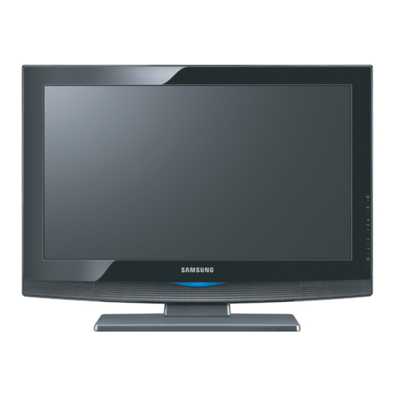
  • Page 1 LCD-TV Chassis : G3F26CCN G3F32CCN Model : LA26B350F1 LA32B350F1 SERVICE Manual TFT-LCD TV Contents 1. Precautions 2. Product specifications 3. Disassembly and Reassembly 4. Troubleshooting 5. Exploded View & Part List 6. Wiring Diagram LA26B350F1/LA32B350F1 Refer to the service manual in the GSPN (see the rear cover) for the more information.
  • Page 2: Table Of Contents

    4-3. Factory Mode Adjustments ................... 4-14 4-4. White Balance - Calibration ..................4-24 4-5. HOW TO UPGRADE ....................4-26 5. Exploded View & Part List ..................5-1 5-1. LA26B350F1 Exploded View ..................5-1 5-2. LA32B350F1 Exploded View ..................5-3 5-3. LA26B350F1 Parts List ....................5-5 5-4. LA32B350F1 Parts List ....................5-22 6. Wiring Diagram ......................
  • Page 3 GSPN (Global Service Partner Network) Area Web Site North America http://service.samsungportal.com Latin America http://latin.samsungportal.com http://cis.samsungportal.com Europe http://europe.samsungportal.com China http://china.samsungportal.com Asia http://asia.samsungportal.com Mideast & Africa http://mea.samsungportal.com © 2009 Samsung Electronics Co.,Ltd. This Service Manual is a property of Samsung Electronics Co.,Ltd. All rights reserved. Any unauthorized use of Manual can be punished under applicable Printed in Korea International and/or domestic law. P/N: BN82-00590A-00...
  • Page 4 3. Disassembly and Reassembly 3. Disassembly and Reassembly This section of the service manual describes the disassembly and reassembly procedures for the LA32B350F1 LCD TV. WARNING: This LCD TV contains electrostatically sensitive devices. Use caution when handling these components. 3-1. Disassembly and Reassembly Cautions: 1.
  • Page 5 3. Disassembly and Reassembly Description Picture Description Screws 2. Lift up rear cover and remove the stand. 3. Remove Screw from the stand BRKT and top BRKT. Lift up the stand BRKT and top.
  • Page 6 3. Disassembly and Reassembly Description Picture Description Screws 4. Disonnect cable from the boards. 5. Lift up the LCD panel. Reassembly procedures are in the reverse order of disassembly procedures. ※...
  • Page 7 5. Exploded View & Part List 5. Exploded View & Part List 5-1. LA26B350F1 Exploded View M0013 M0146 M0014 M0215 M0115 M0107 T0003 T0920 M0027 T0175...
  • Page 8 5. Exploded View & Part List 5-1-1. LA26B350F1 Parts List Description & Specification Location No. Code No. Q’ty S.A/S.N.A Remark T0003 BN96-10891F ASSY COVER P-FRONT;ABS Natural,GDM1903 T0175 BN96-04769D ASSY SPEAKER P;16ohm,4pin,5W,L350 26, 32 M0215 BN07-00767A LCD-PANEL;LTF260AP03 M0115 BN61-04772A BRACKET-STAND LINK;B450 26inch,SECC S.N.A...
  • Page 9 5. Exploded View & Part List 5-2. LA26B350F1 Parts List Service Bom (SA: SERVICE AVAILABLE, SNA: SERVICE NOT AVAILABLE) Description & Specification Level Location No. Code No. Q’ty SA/SNA Remark LA26B350F1LSG LA26B350F1,N66E/26BF1-G3F,26,LCD-TV,SRI M0001 BN90-02190C ASSY COVER FRONT;26,LB350,SO S.N.A T0175 BN96-04769D ASSY SPEAKER P;16ohm,4pin,5W,L350 26, 32...
  • Page 10 5. Exploded View & Part List Description & Specification Level Location No. Code No. Q’ty SA/SNA Remark M0014 BN94-02965Q ASSY PCB MAIN;LA26B350F1 ...3 T0245 0202-001608 SOLDER-WIRE FLUX;LFC7-107,D0.8,99.3Sn/0. 0.25 S.N.A ...3 JA4005 3701-001480 CONNECTOR-DSUB;15P,3R,FEMAIL,STAMPED PIN ...3 CN330 3711-004531 HEADER-BOARD TO CABLE;BOX,10P,1R,2mm,ANG ...3...
  • Page 11 5. Exploded View & Part List Description & Specification Level Location No. Code No. Q’ty SA/SNA Remark ..4 D4001 0403-000771 DIODE-ZENER;VLZ6V2B,5.96-6.27V,500mW,SOD ..4 D4003 0403-000771 DIODE-ZENER;VLZ6V2B,5.96-6.27V,500mW,SOD ..4 D4004 0403-000771 DIODE-ZENER;VLZ6V2B,5.96-6.27V,500mW,SOD ..4 D4006 0403-000771 DIODE-ZENER;VLZ6V2B,5.96-6.27V,500mW,SOD ..4 D4007 0403-000771 DIODE-ZENER;VLZ6V2B,5.96-6.27V,500mW,SOD ..4 D4008 0403-000771 DIODE-ZENER;VLZ6V2B,5.96-6.27V,500mW,SOD ..4 D6001...
  • Page 12 5. Exploded View & Part List Description & Specification Level Location No. Code No. Q’ty SA/SNA Remark ..4 IC6002 1203-004363 IC-VOL. DETECTOR;RT9818C-29PV,SOT-23,3P, ..4 IC2003 1203-004364 IC-VOL. DETECTOR;RT9818C-42PV,SOT-23,3P, ..4 T0170 1203-005463 IC-SWITCH VOL. REG.;MIC2605YML,MLF,8P,2x ..4 IC1004 1203-005538 IC-DC/DC CONVERTER;AOZ1021HAIL,SOP,8P,4..4 IC7005 1205-003201 IC-BUS SWITCH;TC7WB125FK,SSOP,8P,2x2.3mm ..4...
  • Page 13 5. Exploded View & Part List Description & Specification Level Location No. Code No. Q’ty SA/SNA Remark ..4 R6004 2007-000138 R-CHIP;100ohm,5%,1/16W,TP,1005 S.N.A ..4 R6005 2007-000138 R-CHIP;100ohm,5%,1/16W,TP,1005 S.N.A ..4 R6034 2007-000138 R-CHIP;100ohm,5%,1/16W,TP,1005 S.N.A ..4 R6036 2007-000138 R-CHIP;100ohm,5%,1/16W,TP,1005 S.N.A ..4 R6037 2007-000138 R-CHIP;100ohm,5%,1/16W,TP,1005 S.N.A ..4...
  • Page 14 5. Exploded View & Part List Description & Specification Level Location No. Code No. Q’ty SA/SNA Remark ..4 R2012 2007-000140 R-CHIP;1Kohm,5%,1/16W,TP,1005 S.N.A ..4 R3023 2007-000140 R-CHIP;1Kohm,5%,1/16W,TP,1005 S.N.A ..4 R3056 2007-000140 R-CHIP;1Kohm,5%,1/16W,TP,1005 S.N.A ..4 R4056 2007-000140 R-CHIP;1Kohm,5%,1/16W,TP,1005 S.N.A ..4 R6003 2007-000140 R-CHIP;1Kohm,5%,1/16W,TP,1005 S.N.A ..4...
  • Page 15 5. Exploded View & Part List Description & Specification Level Location No. Code No. Q’ty SA/SNA Remark ..4 R3071 2007-000148 R-CHIP;10Kohm,5%,1/16W,TP,1005 S.N.A ..4 R3073 2007-000148 R-CHIP;10Kohm,5%,1/16W,TP,1005 S.N.A ..4 R3075 2007-000148 R-CHIP;10Kohm,5%,1/16W,TP,1005 S.N.A ..4 R3082 2007-000148 R-CHIP;10Kohm,5%,1/16W,TP,1005 S.N.A ..4 R3085 2007-000148 R-CHIP;10Kohm,5%,1/16W,TP,1005 S.N.A ..4...
  • Page 16 5. Exploded View & Part List Description & Specification Level Location No. Code No. Q’ty SA/SNA Remark ..4 R2006 2007-000171 R-CHIP;0ohm,5%,1/16W,TP,1005 S.N.A ..4 R2028 2007-000171 R-CHIP;0ohm,5%,1/16W,TP,1005 S.N.A ..4 R2029 2007-000171 R-CHIP;0ohm,5%,1/16W,TP,1005 S.N.A ..4 R3003 2007-000171 R-CHIP;0ohm,5%,1/16W,TP,1005 S.N.A ..4 R3005 2007-000171 R-CHIP;0ohm,5%,1/16W,TP,1005 S.N.A ..4...
  • Page 17 5. Exploded View & Part List Description & Specification Level Location No. Code No. Q’ty SA/SNA Remark ..4 R6094 2007-000172 R-CHIP;10ohm,5%,1/16W,TP,1005 S.N.A ..4 R6096 2007-000172 R-CHIP;10ohm,5%,1/16W,TP,1005 S.N.A ..4 R6100 2007-000172 R-CHIP;10ohm,5%,1/16W,TP,1005 S.N.A ..4 R6102 2007-000172 R-CHIP;10ohm,5%,1/16W,TP,1005 S.N.A ..4 R6105 2007-000172 R-CHIP;10ohm,5%,1/16W,TP,1005 S.N.A ..4...
  • Page 18 5. Exploded View & Part List Description & Specification Level Location No. Code No. Q’ty SA/SNA Remark ..4 R6002 2007-001292 R-CHIP;33ohm,5%,1/16W,TP,1005 S.N.A ..4 R6054 2007-001292 R-CHIP;33ohm,5%,1/16W,TP,1005 S.N.A ..4 R6055 2007-001292 R-CHIP;33ohm,5%,1/16W,TP,1005 S.N.A ..4 R2014 2007-001325 R-CHIP;3.3Kohm,5%,1/16W,TP,1005 S.N.A ..4 R6053 2007-001325 R-CHIP;3.3Kohm,5%,1/16W,TP,1005 S.N.A ..4...
  • Page 19 5. Exploded View & Part List Description & Specification Level Location No. Code No. Q’ty SA/SNA Remark ..4 R7025 2011-001262 R-NETWORK;22ohm,5%,1/16W,L,CHIP,8P,TP,2..4 R7026 2011-001262 R-NETWORK;22ohm,5%,1/16W,L,CHIP,8P,TP,2..4 R7027 2011-001262 R-NETWORK;22ohm,5%,1/16W,L,CHIP,8P,TP,2..4 R7028 2011-001262 R-NETWORK;22ohm,5%,1/16W,L,CHIP,8P,TP,2..4 R7029 2011-001262 R-NETWORK;22ohm,5%,1/16W,L,CHIP,8P,TP,2..4 R7030 2011-001262 R-NETWORK;22ohm,5%,1/16W,L,CHIP,8P,TP,2.
  • Page 20 5. Exploded View & Part List Description & Specification Level Location No. Code No. Q’ty SA/SNA Remark ..4 C4030 2203-002285 C-CER,CHIP;10nF,10%,50V,X7R,1005 S.N.A ..4 C4031 2203-002285 C-CER,CHIP;10nF,10%,50V,X7R,1005 S.N.A ..4 C4032 2203-002285 C-CER,CHIP;10nF,10%,50V,X7R,1005 S.N.A ..4 C4005 2203-002525 C-CER,CHIP;0.56nF,10%,50V,X7R,TP,1005 S.N.A ..4 C4009 2203-002525 C-CER,CHIP;0.56nF,10%,50V,X7R,TP,1005 S.N.A ..4...
  • Page 21 5. Exploded View & Part List Description & Specification Level Location No. Code No. Q’ty SA/SNA Remark ..4 C6016 2203-006126 C-CER,CHIP;47NF,10%,16V,X7R,TP,1005 S.N.A ..4 C6017 2203-006126 C-CER,CHIP;47NF,10%,16V,X7R,TP,1005 S.N.A ..4 C6018 2203-006126 C-CER,CHIP;47NF,10%,16V,X7R,TP,1005 S.N.A ..4 C6022 2203-006126 C-CER,CHIP;47NF,10%,16V,X7R,TP,1005 S.N.A ..4 C6023 2203-006126 C-CER,CHIP;47NF,10%,16V,X7R,TP,1005 S.N.A ..4...
  • Page 22 5. Exploded View & Part List Description & Specification Level Location No. Code No. Q’ty SA/SNA Remark ..4 C3005 2203-006361 C-CER,CHIP;10000nF,10%,10V,X5R,TP,2012 ..4 C3013 2203-006361 C-CER,CHIP;10000nF,10%,10V,X5R,TP,2012 ..4 C4008 2203-006361 C-CER,CHIP;10000nF,10%,10V,X5R,TP,2012 ..4 C4012_OP 2203-006361 C-CER,CHIP;10000nF,10%,10V,X5R,TP,2012 ..4 C4017 2203-006361 C-CER,CHIP;10000nF,10%,10V,X5R,TP,2012 ..4 C4023_OP 2203-006361 C-CER,CHIP;10000nF,10%,10V,X5R,TP,2012 ..4 C6003...
  • Page 23 5. Exploded View & Part List Description & Specification Level Location No. Code No. Q’ty SA/SNA Remark ..4 C7014 2203-006681 C-CER,CHIP;100nF,+80-20%,25V,Y5V,1005 S.N.A ..4 C7015 2203-006681 C-CER,CHIP;100nF,+80-20%,25V,Y5V,1005 S.N.A ..4 C7017 2203-006681 C-CER,CHIP;100nF,+80-20%,25V,Y5V,1005 S.N.A ..4 C7018 2203-006681 C-CER,CHIP;100nF,+80-20%,25V,Y5V,1005 S.N.A ..4 C7019 2203-006681 C-CER,CHIP;100nF,+80-20%,25V,Y5V,1005 S.N.A ..4...
  • Page 24 5. Exploded View & Part List Description & Specification Level Location No. Code No. Q’ty SA/SNA Remark ..4 F103 2901-001506 FILTER-EMI SMD;5V,0.13A,0pF,2x1x0.5mm,TP ..4 T0568 3301-000314 BEAD-SMD;120ohm,1.6x0.8x0.8mm,-,-,- S.N.A ..4 T0568 3301-000314 BEAD-SMD;120ohm,1.6x0.8x0.8mm,-,-,- S.N.A ..4 T0568 3301-001236 BEAD-SMD;60ohm,1608 S.N.A ..4 T0568 3301-001236 BEAD-SMD;60ohm,1608 S.N.A ..4...
  • Page 25 BAG PE;LDPE,T0.05,W400,L240,TRP,8,2,8.00 S.N.A ...3 AA68-03242M MANUAL FLYER-MANUAL FLYER-06,S;comm,Sams S.N.A ...3 T0511 BN68-00968F MANUAL USERS;LA32R81BM/XTL,SIEL,ENGLISH, S.N.A ...3 BN68-01420C MANUAL FLYER-SAFETY NOTICE FOR;All model S.N.A ...3 M0156 BN68-02101A MANUAL USERS-01;B360 B350,SAMSUNG,ENG,AS S.N.A M0045 BN92-05035A ASSY ACCESSORY;LA26B350F1XXZ S.N.A M0019 BN92-05045C ASSY LABEL;LA26B350F1LXL,SIEL,INDIA S.N.A 5-19...
  • Page 26: Precautions

    1. Precautions 1. Precautions 1-1. Safety Precautions Follow these safety, servicing and ESD precautions to prevent damage and to protect against potential hazards such as electrical shock. 1-1-1. Warnings For continued safety, do not attempt to modify the circuit board. Disconnect the AC power and DC power jack before servicing.
  • Page 27: Servicing Precautions

    1. Precautions 1-2. Servicing Precautions WARNING: An electrolytic capacitor installed with the wrong polarity might explode. Caution: Before servicing units covered by this service manual, read and follow the Safety Precautions section of this manual. Note: If unforeseen circumstances create conflict between the following servicing precautions and any of the safety precautions, always follow the safety precautions.
  • Page 28: Installation Precautions

    1. Precautions 1-4. Installation Precautions For safety reasons, more than a people are required for carrying the product. Keep the power cord away from any heat emitting devices, as a melted covering may cause fire or electric shock. Do not place the product in areas with poor ventilation such as a bookshelf or closet. The increased internal temperature may cause fire.
  • Page 29 1. Precautions Memo...
  • Page 30: Product Specifications

    2. Product specifications 2. Product specifications 2-1. Feature & Specifications Model LA26B350F1 Feature RF, 1-HDMI, 1-HDMI/DVI, 1-Component, 1-AV, D-sub � Brightness : 450cd/m � Contrast Ratio : 3000:1 � Response time : 8ms � Dynamic contrast, PVA, TN � PIP(in HDMI 1, 2, 3, Component 1, PC Mode and Sub picture is available only in TV analog mode) �...
  • Page 31 2. Product specifications Model LA32B350F1 Feature RF, 1-HDMI, 1-HDMI/DVI, 1-Component, 1-AV, D-sub � Brightness : 450cd/m � Contrast Ratio : 3000:1 � Response time : 8ms � Dynamic contrast, Super-PVA � PIP(in HDMI 1, 2, 3, Component 1, PC Mode and Sub picture is available only in TV analog mode) �...
  • Page 32 2. Product specifications CHANNEL FREQUENCY TABLE OUTPUT FREQUENCY : ANALOG fv:45.75MHz, fs:41.25MHz DIGITAL Fc:44MHz TUNING STEP SIZE : FIRST PLL 250KHz SECOND PLL 62.5KHz OSD CH NO CH NO CH NO CH NO Air-DTV Air-NTSC BAND Cable STD BAND Cable HRC Cable IRC 72.
  • Page 33 2. Product specifications OSD CH NO CH NO CH NO CH NO Air-DTV Air-NTSC BAND Cable STD BAND Cable HRC Cable IRC 499.25 ULTRA 498.00 499.25 505.25 ULTRA 504.00 505.25 511.25 ULTRA 510.00 511.25 517.25 ULTRA 516.00 517.25 523.25 ULTRA 522.00 523.25 529.25...
  • Page 34: Specification Comparison To Old Models

    2. Product specifi cations 2-2. Specifi cation Comparison to Old Models Model B350(LA26/32B350F1) Coral (LA26/32A450C1) Design Display Type LCD TV LCD TV Built-in Tuner Resolution 1366 x 768 1366 x 768 LCD Panel TFT LCD Panel 50Hz TFT LCD Panel 50Hz Screen Size 26”/32”...
  • Page 35 Remark Remote Control & Batteries BN59-00880A (AAA x 2) Power Cord 3903-000172 Cover-Bottom BN63-05618B Samsung Electronics Service center Owner’s Instructions BN68-02101H Warranty Card / Registration Card / Safety Guide Manual AA68-03184A (Not available in all locations) Stand Screw x 4 6002-001294 BN90-02198A(26”)
  • Page 36: Troubleshooting

    4. Troubleshooting 4. Troubleshooting 4-1. Troubleshooting Check the various cable connections first. • Check to see if there is a burnt or damaged cable. • Check to see if there is a disconnected or loose cable connection. • Check to see if the cables are connected according to the connection diagram. Check the power input to the Main Board.
  • Page 37 4. Troubleshooting 4-1-1. No Power The LEDs on the front panel do not work when connecting the power cord. The SMPS relay does not work when connecting the power cord. Symptom The units appears to be dead. The IP relay or the LEDs on the front panel does not work when connecting the power cord if the cables are improperly connected or the Main Board or SMPS is not functioning.
  • Page 38 Does the digital data appear at the output of LVDS Cable? Change a main PCB ass’y Check a LVDS cable? Replace a lcd panel? Please, Call to Samsung Co. LTD. Caution Make sure to disconnect the power before working on the IP board.
  • Page 39 4. Troubleshooting WAVEFORMS R,G,B Output Signal...
  • Page 40 4. Troubleshooting 4-1-3. No Video (HDMI - Digital Signal) Symptom Audio is normal but no picture is displayed on the screen. Check the HDMI source Major Check the M-star checkpoints This may happen when the LVDS cable connecting the Main Board and the Panel is disconnected. Power Indicator is off.
  • Page 41 4. Troubleshooting WAVEFORMS Digital Output Data Signal of HDMI(Data)
  • Page 42 Does the Signal appear at c6025 Change a main PCB ass’y. of IC6003? Check the LVDS cable? Replace the LCD panel? Please, Call to Samsung Co. LTD. Caution Make sure to disconnect the power before working on the IP board.
  • Page 43 4. Troubleshooting WAVEFORMS CVBS Output Signal Tuner_CVBS Output Signal...
  • Page 44 Diagnostics Does the signal appear at C6018, Check a connection harness. C6021 of IC6003? Check a LVDS cable ? Replcelcd panel? Please, Call to Samsung Co. LTD. Caution Make sure to disconnect the power before working on the IP board.
  • Page 45 4. Troubleshooting WAVEFORMS CVBS Output Signal 4-10...
  • Page 46 4. Troubleshooting 4-1-6. No Sound Symptom Audio is normal but no picture is displayed on the screen. Check the RF Source Major Check the M-star checkpoints This may happen when the LVDS cable connecting the Main Board and the Panel is disconnected. Connect a sound cable.
  • Page 47 4. Troubleshooting WAVEFORMS The Signal are Inputed to IC1201 The Signal are Inputed to IC1202 4-12...
  • Page 48: Alignments And Adjustments

    4. Troubleshooting 4-2. Alignments and Adjustments 4-2-1. General Alignment Instuction Usually, a color LCD-TV needs only slight touch-up adjustment upon installation. Check the basic characteristics such as height, horizontal and vertical sync. Use the specified test equipment or its equivalent. Correct impedance matching is essential.
  • Page 49 4. Troubleshooting 4-3. Factory Mode Adjustments 4-3-1 Entering Factory Mode To enter ‘Service Mode’ Press the remote -control keys in this sequence : - If you do not have Factory remote - control INFO MENU MUTE Power on - If you have Factory remote - control PICTURE ON DISPLAY FACTORY...
  • Page 50 PB350, PB430, PB450, PB550, PB550_FBE, L_ BASIC, LB350, LB360, LB360_22, LB450, LB450_22, LB460, LB480, LB480_22, LB530, LB550, B550_FBE, LB622, LB550_FBE_NM Tuner Select SEMCO SEMCO, XUGUANG Samsung Samsung Ch Table SUWON SUWON, SESK, SHE, TTSEC, SEIN, SDMA, TSED, SAVINA, SIEL, TSE Local Set...
  • Page 51 4. Troubleshooting ADC Result 1st_AV_Gain 0 ~ 255 1st_AV_Offset 0 ~ 255 1st_Comp_Gain 0 ~ 255 1st_Comp_Gain_Cb 0 ~ 255 1st_Comp_Gain_Cr 0 ~ 255 1st_Comp_Offset 0 ~ 255 1st_Comp_Offset_Cb 0 ~ 255 1st_Comp_Offset_Cr 0 ~ 255 1st_PC_R_Gain 0 ~ 255 1st_PC_G_Gain 0 ~ 255 1st_PC_B_Gain...
  • Page 52 4. Troubleshooting Control  EDID EDID Protect On/Off EDID Type L13_1920_1080 P12_1024_768, P13_1024_768, P12_1366_768, P13_1366_768, P12_1920_1080, P13_1920_1080, L12_1366_768, L13_1366_768, L12_1920_1080, L13_1920_1080 EDID Write(0x4D,0) L13_1920_1080 P12_1024_768, P13_1024_768, SUCCESS P12_1366_768, P13_1366_768, P12_1920_1080, P13_1920_1080, L12_1366_768, L13_1366_768, L12_1920_1080, L13_1920_1080 Video Mute Time 0~99 Sub Option Inch 32”...
  • Page 53 4. Troubleshooting Hotel Option  Hotel Option Hotel Mode On/Off Shop Option  Shop Option Shop Mode On/Off Sound  Detection Threshold OPTION RANGE SOUND Pilot Threshold M2S Thr High 0~255 M2S Thr Low 0~255 S2M Thr High 0~255 S2M Thr Low 0~255 Carrier1 Threshold Amp On Thr High 0~255...
  • Page 54 4. Troubleshooting MST69A84HQ  VDEC SYNC_LVL 0~255 HPLL_MD HPLL_SPD1 0~63 HPLL_SPD2 0~255 CBCRLP_MD YC_DLY IFCOMP 0~63 SAT_ADJ 0~255 YSEPFLT NOISE_LVL 0~255 Film Det Speed NT 0~255 IPC/MJC Film Det Speed PAL 0~255 Motion Hist Motion History Red Sat 0~30 Color Space Red Hue 0~127 Green Sat...
  • Page 55 4. Troubleshooting  Pattern Select 0~25 B-Slope Gain 0~255 B-Tilt Min 0~255 B-Tilt Max 0~255 LFuc-Basis 0~255 HFuc-Basis 0~255 Mean-Offset1 0~255 Mean-Offset2 0~255 Mean-Slope 0~255 ACR Offset 0~127 ACR Th1 0~255 ACR Th2 0~255 Skin Enable 0~255 Skin Uv 0~255 Mskin Uv 0~255 Sub Color...
  • Page 56 4. Troubleshooting EPA Standard  Std Contr 0~100 EPA Standard Std Bright 0~100 Std Sharp 0~100 Std Color 0~100 Std Tint 0~100 Std Backlight 0~10 Adjust  Adjust Dynamic Dimming On/Off Dynamic CE Dynamic CE On/Off B Slope On/Off LNA Plus RF Db 0 Level 0~255 RF Db 1 Level...
  • Page 57 4. Troubleshooting YC_Delay  PAL BG YC Delay PAL DK PAL I SECAM BG SECAM DK SECAM L NTSC 358 NTSC 443 AV PAL AV SECAM AV NT358 AV NT443 AV PAL60 Sharpness  Sharpness H1 Gain 0~63 H2 Gain 0~63 H3Gain 0~63...
  • Page 58 4. Troubleshooting  Skin X 0~11 Skin Y 0~11 B Slope 0~255 DLC ML 0~255 DLC_MH 0~255 DLC_H 0~255 Skin_SAT 0~15 Skin_Hue 0~127 M_Skin_Hue M_Skin_X 0~11 M_Skin_Y 0~11 Mid_color_level 0~255 M_Mid_color_level 0~255 EEPROM Reset  EEPROM Reset EEPROM Reset NVR All Clear On/Off Defect Log ...
  • Page 59 4. Troubleshooting 4-4. White Balance - Calibration 4-4-1 White Balance -Calibration 1. Calibration AV Calibration Comp Calibration PC Calibration HDMI Calibration 4-4-2 Service Adjustment - You must perform Calibration in the Lattice Pattern before adjusting the White Balance. Color Calibration ...
  • Page 60 4. Troubleshooting Method of Color Calibration (AV)  1) Apply the NTSC Lattice (N0. 3) pattern signal to the AV IN 1 port 2) Press the Source key to switch to “AV1” mode 3) Enter Service mode 4) Select the “Calibration” menu 5) Select the “AV Calibration”...
  • Page 61: How To Upgrade

    4. Troubleshooting 4-4-3 White Balance - Adjustment (low light) (hight light) Sub Bright Sub Contrast 5. W/B R offset R gain G offset G gain B offset B gain (W/B adjustment Condition refer next page) 4-5. HOW TO UPGRADE 4-5-1 Software Upgrade (MSTAR ISP Tool) MSTAR ISP TOOL ...
  • Page 62: Wiring Diagram

    6. Wiring Diagram 6. Wiring Diagram 6-1. Wiring Diagram Function Function...
  • Page 63 6. Wiring Diagram COMP1(JA5001) PC/DVI SOUND INPUT(JA4001) POWER and Dimming(CN1001) COMP1_Y IDENT_COMP2 PC_SR_IN COMP1_PB PC_SL_IN COMP1_PR PC_SL_IN B3.3VD COMP1_SL_IN PC_SL_IN COMP1_SR_IN PC_SR_IN A13V PC_SR_IN A13V PC INPUT(JA4005) PC_RED AV1 INPUT(JA5003) PC_GREEN PC_BLUE A13V IDENT_SIDE_AV2 AV1_CVBS_IN AV1_SR_IN AV1_SL_IN HDMI1 Connection(JA3001) PC_5V AV1_SL_IN PC_IDENT HDMI1_RX2+...
  • Page 64 6. Wiring Diagram HDMI2 Connection(JA3004) HDMI2_RX2+ HDMI2_RX2- HDMI2_RX1+ HDMI2_RX1- HDMI2_RX0+ HDMI2_RX0- HDMI2_RXCLK+ HDMI2_RXCLK- HDMI_CEC HDMI2_DDC_SCL HDMI2_DDC_SDA HDMI2_5V / IDENT_HDMI HDMI2_5V / IDENT_HDMI...
  • Page 65: Wiring Picture

    6. Wiring Diagram 6-2. Wiring Picture...
  • Page 66: Connector Functions

    6. Wiring Diagram 6-3. Connector Functions Connector Functions CN1001 <-> SMPS Supply dimming power from SMPS to Main Board. * defective symptom : abnormal Picture CN2001 <-> Speaker Connection Main Board and Speaker. * defective symptom : No picture CN4007 <-> Function & IR Connection Main Board and Function &...
  • Page 67: Cables

    6. Wiring Diagram 6-4. Cables (1) LVDS CONNECTOR (2) CONNECTOR POWER 30P (3) ASSY-SPEAKER BN96-07766S (26”) BN39-00691L (26”) Code BN96-04769C (26”, 32”) BN96-07766R (32”) BN39-00691K (32”) Photo (4) IR to FUNCTION Code BN96-10997B (26”, 32”) Photo...

This manual is also suitable for:

La32b350f1

Table of Contents