Table of Contents
Advertisement
Quick Links
INSTALLATION
MANUAL
CONTENTS
GENERAL . . . . . . . . . . . . . . . . . . . . . . . . . . . . . . . . . . . . . . 4
SAFETY CONSIDERATIONS . . . . . . . . . . . . . . . . . . . . . . . 4
INSPECTION . . . . . . . . . . . . . . . . . . . . . . . . . . . . . . . . . . . . 4
REFERENCE . . . . . . . . . . . . . . . . . . . . . . . . . . . . . . . . . . . . 4
RENEWAL PARTS . . . . . . . . . . . . . . . . . . . . . . . . . . . . . . . 5
APPROVALS . . . . . . . . . . . . . . . . . . . . . . . . . . . . . . . . . . . . 5
PRODUCT NOMENCLATURE . . . . . . . . . . . . . . . . . . . . . . 6
INSTALLATION . . . . . . . . . . . . . . . . . . . . . . . . . . . . . . . . . . 7
OPERATION . . . . . . . . . . . . . . . . . . . . . . . . . . . . . . . . . . . 38
START-UP (COOLING) . . . . . . . . . . . . . . . . . . . . . . . . . . . 45
START-UP (GAS HEAT) . . . . . . . . . . . . . . . . . . . . . . . . . . 46
TROUBLESHOOTING . . . . . . . . . . . . . . . . . . . . . . . . . . . . 48
See the following page for a complete Table of Contents.
NOTES, CAUTIONS AND WARNINGS
The installer should pay particular attention to the words:
NOTE, CAUTION, and WARNING. Notes are intended to
clarify or make the installation easier. Cautions are given to
prevent equipment damage. Warnings are given to alert
installer that personal injury and/or equipment damage may
result if installation procedure is not handled properly.
CAUTION:
READ ALL SAFETY GUIDES BEFORE YOU
BEGIN TO INSTALL YOUR UNIT.
SAVE THIS MANUAL
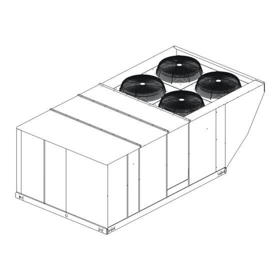
GAS/ELECTRIC SINGLE PACKAGE
AIR CONDITIONERS
MODELS: DW-15, -18, -20 & -25
035-18576-002-A-1103
Advertisement
Table of Contents
Troubleshooting

Related Manuals for SUNLINE 2000 DW-15

Summary of Contents for SUNLINE 2000 DW-15
- Page 1 MANUAL AIR CONDITIONERS MODELS: DW-15, -18, -20 & -25 CONTENTS GENERAL ........4 SAFETY CONSIDERATIONS .
-
Page 2: Table Of Contents
035-18576-002-A-1103 TABLE OF CONTENTS GENERAL ........4 ECONOMIZER (SINGLE OR DUAL) WITH POWER EXHAUST - . - Page 3 035-18576-002-A-1103 LIST OF FIGURES LIST OF TABLES Fig. # Pg. # Tbl. # Pg. # 1 TYPICAL RIGGING ....... 9 1 UNIT APPLICATION DATA .
-
Page 4: General
035-18576-002-A-1103 GENERAL Model DW units are either single package air condi- tions equipped with optional factory installed electric FIRE OR EXPLOSION HAZARD heaters, or single package gas-fired central heating furnaces with cooling unit. Both are designed for out- Failure to follow safety warnings exactly could door installation on a rooftop or slab. -
Page 5: Renewal Parts
035-18576-002-A-1103 • 035-18920-000 - Economizer Damper • For use with natural gas or propane gas. Accessory • 035-08032-002 - Propane Conversion Accessory (USA) • 035-13073-001 - High Altitude Accessory (Nat. This product must be installed in strict compli- Gas) ance with the enclosed installation instructions and any applicable local, state, and national •... -
Page 6: Product Nomenclature
035-18576-002-A-1103 PRODUCT NOMENCLATURE Unitary Products Group... -
Page 7: Installation
035-18576-002-A-1103 INSTALLATION LIMITATIONS These units must be installed in accordance with the INSTALLATION SAFETY INFORMATION: following national and local safety codes: Read these instructions before continuing this appli- In U.S.A.: ance installation. This is an outdoor combination heat- ing and cooling unit. The installer must assure that •... -
Page 8: Location
035-18576-002-A-1103 TABLE 1: UNIT APPLICATION DATA UNIT MODEL NUMBER DW-15 DW-18 DW-20 DW-25 208/230-3-60 187 / 253 Voltage Varation, Min. 460-3-60 414 / 506 / Max. 575-3-60 518 / 630 Supply Air CFM, Min. / Max. 4,500 / 7,000 6,000 / 8,750... -
Page 9: Rigging And Handling
035-18576-002-A-1103 RIGGING AND HANDLING Exercise care when moving the unit. Do not remove any packaging until the unit is near the place of installa- tion. Rig the unit by attaching chain or cable slings to the round lifting holes provided in the base rails. Spreaders, whose length exceeds the largest dimen- sion across the unit, MUST BE USED. -
Page 10: Ductwork
035-18576-002-A-1103 FIXED OUTDOOR AIR INTAKE DAMPER This damper is shipped inside the return air compart- ment. It is completely assembled and ready for installa- Do not permit overhanging structures or shrubs tion. A damper baffle inside of the hood is adjustable to to obstruct outdoor air discharge outlet, com- provide variable amounts of outdoor air intake on units bustion air inlet or vent outlets. -
Page 11: Condensate Drain
035-18576-002-A-1103 COMPRESSORS Units are shipped with compressor mountings factory- adjusted and ready for operation. Do not loosen compressor mounting bolts. FILTERS Two-inch filters are supplied with each unit, but units can be converted easily to four-inch filters. Filters must always be installed ahead of the evaporator coil and must be kept clean or replaced with same size and type. - Page 12 035-18576-002-A-1103 THERMOSTAT TERMINALS UNIT CONTROL BOARD 24 Volt Transformer TO REMOTE SENSOR 2ET04701324 IF USED Electronic programmable Thermostat 2ET0770010024 (includes subbase). Terminals A1 and A2 provide a relay output to close the outdoor economizer dampers when the thermostat switches to the set-back position. T - S T A T O C C U N I T C O N T R O L...
-
Page 13: Thermostat
035-18576-002-A-1103 THERMOSTAT with a separate branch circuit fed directly from the meter panel and properly fused. The room thermostat should be located on an inside wall approximately 56 inches above the floor where it will not be subject to drafts, sun exposure or heat from electrical fixtures or appliances. -
Page 14: Optional Gas Heat
035-18576-002-A-1103 OPTIONAL GAS HEAT These gas-fired heaters have aluminized-steel or All gas heaters are shipped from the factory equipped optional stainless steel, tubular heat exchangers with for natural gas use, but can be field converted to L.P./ spark ignition with proven pilot. Propane with Kit Model # 1NP0418. -
Page 15: L.p. Units, Tanks And Piping
035-18576-002-A-1103 7. A 1/8 inch NPT plugged tap, accessible for test gage connection, must be installed immediately upstream of the gas supply connection to the fur- nace. Natural gas may contain some propane. Pro- pane, being an excellent solvent, will quickly dissolve white lead or most standard commer- cial compounds. -
Page 16: Vent And Combustion Air Hoods
035-18576-002-A-1103 Maintaining proper gas pressure depends on three The screen for the combustion air intake hood is main factors: secured to the inside of the access panel opening with four fasteners and the screws used for mounting the 1. The vaporization rate depends on (a) the tempera- hood to the panel. -
Page 17: Optional Economizer And Power Exhaust Damper Set Point Adjustments And Informa- Tion
035-18576-002-A-1103 angles, and the wiring are factory installed as part of • For a single enthalpy operation carefully turn the the power exhaust option. set point adjusting screw (found on the damper control module) to the "A", "B", "C" or "D" setting All of the components, including the dampers, hard- corresponding to the lettered curve of the Enthalpy ware, and mounting instructions are shipped in a single... -
Page 18: Enthalpy Setpoint Adjustment
035-18576-002-A-1103 CONTROL POINT CONTROL APPROX. CURVE (29) (32) (35) (38) (41) (43) AT 50% RH 73 (23) 70 (21) (27) 67 (19) 63 (17) (24) (21) (18) (16) (13) (10) (24) (27) (41) (43) (10) (13) (16) (18) (21) (29) (32) (35) (38) -
Page 19: Four And Six Point Loads
035-18576-002-A-1103 FIGURE 11 - FOUR AND SIX POINT LOADS TABLE 6: FOUR AND SIX POINT LOADS Total 4 Point Loads (lbs) Unit Size Shipping Weight 180 Gas 2660 210 Gas 2928 240 Gas 2960 300 Gas 3046 180 Elec 2460 210 Elec 2728 240 Elec... -
Page 20: Physical Data
035-18576-002-A-1103 TABLE 7: PHYSICAL DATA MODELS DW-15 DW-18 DW-20 DW-25 EVAPORATOR CENTRIFUGAL BLOWER (Dia.x Wd.) 15x15 18x15 18x15 18x15 BLOWER FAN MOTOR HP ROWS DEEP EVAPORATOR FINS PER INCH 13.5 COIL FACE AREA (Sq. Ft.) PROPELLER DIA. (In.) (Each) CONDENSER FAN... -
Page 21: Dw Electrical Data Without Powered Convenience Outlet
035-18576-002-A-1103 TABLE 8: DW ELECTRICAL DATA WITHOUT POWERED CONVENIENCE OUTLET COMPRESSORS HEATER OPTION MAX. MIN. FUSE/ OD FAN CONV MODEL BLOWER CIRCUIT VOLTAGE MOTORS OUTLET BRKR TONNAGE MOTOR MODEL STAGES AMPS AMPACITY EACH EACH FLA EACH AMPS SIZE (AMPS) (AMPS) None 74.2 13.5... - Page 22 035-18576-002-A-1103 TABLE 8: DW ELECTRICAL DATA WITHOUT POWERED CONVENIENCE OUTLET (CONTINUED) COMPRESSORS HEATER OPTION MAX. MIN. FUSE/ OD FAN CONV MODEL BLOWER CIRCUIT VOLTAGE MOTORS OUTLET BRKR TONNAGE MOTOR MODEL STAGES AMPS AMPACITY EACH EACH FLA EACH AMPS SIZE (AMPS) (AMPS) None 110.4...
-
Page 23: Dw Electrical Data With Powered Convenience Outlet
035-18576-002-A-1103 TABLE 9: DW ELECTRICAL DATA WITH POWERED CONVENIENCE OUTLET COMPRESSORS HEATER OPTION MAX. MIN. FUSE/ OD FAN CONV MODEL BLOWER CIRCUIT VOLTAGE MOTORS OUTLET BRKR TONNAGE MOTOR MODEL STAGES AMPS AMPACITY EACH EACH FLA EACH AMPS SIZE (AMPS) (AMPS) None 84.2 13.5... - Page 24 035-18576-002-A-1103 TABLE 9: DW ELECTRICAL DATA WITH POWERED CONVENIENCE OUTLET (CONTINUED) COMPRESSORS HEATER OPTION MAX. MIN. FUSE/ OD FAN CONV MODEL BLOWER CIRCUIT VOLTAGE MOTORS OUTLET BRKR TONNAGE MOTOR MODEL STAGES AMPS AMPACITY EACH EACH FLA EACH AMPS SIZE (AMPS) (AMPS) None 120.4...
- Page 25 035-18576-002-A-1103 ECONOMIZER / MOTORIZED DAMPER FIXED OUTDOOR INTAKE AIR AND POWER EXHAUST RAIN HOODS (See detail Y) BLOWER MOTOR BLOWER BLOWER COMPARTMENT ACCESS ACCESS ACCESS COMPRESSOR ACCESS 80- 9/32 (Auxillary) (See detail X) 52-5/8 DOT PLUG (For pressure drop reading) GAS OR ELECTRIC COIL...
- Page 26 035-18576-002-A-1103 DUCT COVERS - Units are shipped with the bottom duct openings covered. An accessory flange kit is available for connecting side ducts. For bottom duct applications: 1. Remove the side panels from the supply and return air compartments to gain access to the bottom supply and return air duct covers.
-
Page 27: Supply Air Blower Performance (15 Ton) - Cooling Only 180 Mbh - Bottom Duct
035-18576-002-A-1103 TABLE 10: SUPPLY AIR BLOWER PERFORMANCE (15 TON) - COOLING ONLY 180 MBH - BOTTOM DUCT CONNECTIONS MOTOR BLOWER PULLEY 4500 5250 6000 6750 7200 SPEED, (TURNS (RPM) OPEN)* 208 VOLT AND STANDARD DRIVE 6.0** 4.8. 1010 1040 208 VOLT AND HIGH SPEED DRIVE 1025 1065 1095... -
Page 28: Supply Air Blower Performance (17.5 Ton) - Cooling Only 210 Mbh - Bottom Duct
035-18576-002-A-1103 TABLE 11: SUPPLY AIR BLOWER PERFORMANCE (17.5 TON) - COOLING ONLY 210 MBH - BOTTOM DUCT CONNECTIONS MOTOR BLOWER PULLEY 6000 7000 8000 9000 SPEED, (TURNS (RPM) OPEN)* 208 VOLT AND STANDARD DRIVE 6.0** 1015 208 VOLT AND HIGH SPEED DRIVE 1010 1020 1035... -
Page 29: Supply Air Blower Performance (20 Ton) - Cooling Only 240 Mbh - Bottom Duct
035-18576-002-A-1103 TABLE 12: SUPPLY AIR BLOWER PERFORMANCE (20 TON) - COOLING ONLY 240 MBH - BOTTOM DUCT CONNECTIONS MOTOR BLOWER PULLEY 6000 7000 8000 9000 9400 SPEED, (TURNS (RPM) OPEN)* 208 VOLT AND STANDARD DRIVE 6.0** 1015 208 VOLT AND HIGH SPEED DRIVE 1010 1020 1035... -
Page 30: Supply Air Blower Performance (15 Ton) - Gas Heat 180 Mbh - Bottom Duct Connections
035-18576-002-A-1103 TABLE 13: SUPPLY AIR BLOWER PERFORMANCE (15 TON) - GAS HEAT 180 MBH - BOTTOM DUCT CONNECTIONS MOTOR BLOWER PULLEY 4500 5250 6000 6750 7200 SPEED, (TURNS (RPM) OPEN)* 208 VOLT AND STANDARD DRIVE 6.0** 1010 1040 208 VOLT AND HIGH SPEED DRIVE 1025 1065 1125... -
Page 31: Supply Air Blower Performance (17.5 Ton) - Gas Heat 210 Mbh - Bottom Duct Connections
035-18576-002-A-1103 TABLE 14: SUPPLY AIR BLOWER PERFORMANCE (17.5 TON) - GAS HEAT 210 MBH - BOTTOM DUCT CONNECTIONS MOTOR BLOWER PULLEY 6000 7000 8000 9000 SPEED, (TURNS (RPM) OPEN)* 208 VOLT AND STANDARD DRIVE 6.0** 1015 208 VOLT AND HIGH SPEED DRIVE 1025 1050 1065... -
Page 32: Supply Air Blower Performance (20 Ton) - Gas Heat 240 Mbh - Bottom Duct Connections
035-18576-002-A-1103 TABLE 15: SUPPLY AIR BLOWER PERFORMANCE (20 TON) - GAS HEAT 240 MBH - BOTTOM DUCT CONNECTIONS MOTOR BLOWER PULLEY 6000 7000 8000 9000 9400 SPEED, (TURNS (RPM) OPEN)* 208 VOLT AND STANDARD DRIVE 6.0** 1015 208 VOLT AND HIGH SPEED DRIVE 1025 1050 1065... -
Page 33: Supply Air Blower Performance (25 Ton) - Gas Heat 300 Mbh - Bottom Duct Connections
035-18576-002-A-1103 TABLE 16: SUPPLY AIR BLOWER PERFORMANCE (25 TON) - GAS HEAT 300 MBH - BOTTOM DUCT CONNECTIONS MOTOR BLOWER PULLEY 7500 8750 10000 11250 12500 SPEED, (TURNS (RPM) OPEN)* 208 VOLT AND STANDARD DRIVE 1005 1040 1070 10.2 1100 10.6 1135 11.1... -
Page 34: Connections
035-18576-002-A-1103 TABLE 17: STATIC RESISTANCES RESISTANCE, IWG DESCRIPTION 15 TON 17.5 TON 20 TON 25 TON 4500 6000 7200 6000 7500 9000 6000 8000 9400 7500 10000 12500 WET INDOOR COIL 0.11 0.11 0.11 18 KW 0.31 0.56 0.87 36 KW 0.38 0.68 1.07... -
Page 35: Charging Chart - 15 Ton
035-18576-002-A-1103 15 Ton Charging Chart Outdoor Temp º 105º 95º 85º 75º Suction Pressure (psi) 1. Make sure that both condenser fans are running w hen charging. One fan may sw itch off at low er ambient temperatures making the chart above inaccurate. 2. -
Page 36: Charging Chart - 20 Ton
035-18576-002-A-1103 20 Ton Charging Chart Outdoor Temp (ºF) 115º 105º 95º 85º 75º 65º Suction Pressure (psi) 1. Make sure that both condenser fans are running when charging. One fan may switch off at lower ambient temperatures making the chart above inaccurate. 2. -
Page 37: Phasing
035-18576-002-A-1103 PHASING PROCEDURE FOR ADJUSTING BELT TENSION: MODEL DW units are properly phased at the factory. Loosen nuts (A) (top and bottom). Check for proper compressor rotation. If the blower or Adjust the tension by turning bolt (B). compressors rotate in the wrong direction at start-up, Never loosen nuts (C) from each other. -
Page 38: Operation
035-18576-002-A-1103 Start the supply air blower motor. Adjust the resis- 4. Knowing the pressure drop across a dry coil, the tances in both the supply and the return air duct sys- actual CFM through the unit can be determined tems to balance the air distribution throughout the from the curve in Pressure Drop vs. -
Page 39: Cooling Sequence Of Operation
035-18576-002-A-1103 COOLING SEQUENCE OF OPERATION ECONOMIZER WITH SINGLE ENTHALPY SENSOR - When the room thermostat calls for "first-stage" cool- CONTINUOUS BLOWER ing, the low voltage control circuit from "R" to "G" and By setting the room thermostat fan switch to "ON," the "Y1"... -
Page 40: Motorized Outdoor Air Dampers
035-18576-002-A-1103 exhaust fan setpoint on the economizer control. When associated compressor, initiate the ASCD, and, if the the power exhaust is operating, the second stage of other compressor is idle, stop the condenser fans. mechanical cooling will not operate. As always, the "R" to "G"... -
Page 41: Safety Controls
035-18576-002-A-1103 SAFETY CONTROLS RESET The unit control board monitors the following inputs for Remove the call for cooling, by raising thermostat set- each cooling system: ting higher than the conditioned space temperature. This resets any pressure or freezestat flash codes. 1. -
Page 42: Saftey Controls
035-18576-002-A-1103 This limit is monitored regardless of unit operation sta- FLASH CODES tus, i.e. the limit is monitored at all times. The UCB will initiate a flash code associated with If the temperature limit opens three times within one errors within the system. Refer to UNIT CONTROL hour, it will lock-on the indoor blower motor and a flash BOARD FLASH CODES Table 25. -
Page 43: Gas Heating Operation Errors
035-18576-002-A-1103 motor shaft, closes to power the first stage ignition When the thermostat satisfies de-energizing the module "IC1", thru the "RW1-1 contacts. "RW2"and "RW1", thus opening all gas valves. The blower motor will continue to run after the furnace is Ignition module "IC1"... -
Page 44: Gas Valve
035-18576-002-A-1103 4. Flame Sensor Rod / 100% Ignition Control Lock- GAS VALVE Out. The UCB continuously monitors the GV. Any time the UCB senses voltage at the GV without a call for heat The flame rods and controls are located per Proper for a continuous five-minute period, the UCB will lock- Flame Adjustment Figure 23. -
Page 45: Flash Codes
035-18576-002-A-1103 START-UP (COOLING) PRESTART CHECK LIST I G N . C O N T R O L # 2 After installation has been completed: I G N . C O N T R O L # 1 1. Check the electrical supply voltage being supplied. Be sure that it is the same as listed on the unit R O L L O U T S W . -
Page 46: Shut Down
035-18576-002-A-1103 3. Measure the system Amperage draw across all POST-START CHECK LIST (GAS) legs of 3 phase power wires. After the entire control circuit has been energized and 4. Measure the condenser fan amp draw. the heating section is operating, make the following checks: SHUT DOWN 1. -
Page 47: Manifold Gas Pressure Adjustment
035-18576-002-A-1103 MANIFOLD GAS PRESSURE ADJUSTMENT Put the system into operation and observe through complete cycle to be sure all controls function properly. Small adjustments to the high-fire gas flow may be made by turning the pressure regulator adjusting screw BURNER INSTRUCTIONS on the automatic gas valve. -
Page 48: Checking Gas Input
035-18576-002-A-1103 CHECKING GAS INPUT ADJUSTMENT OF TEMPERATURE RISE The temperature rise (or temperature difference NATURAL GAS between the return air and the heated air from the fur- 1. Turn off all other gas appliances connected to the nace) must lie within the range shown on the rating gas meter. - Page 49 035-18576-002-A-1103 8. If 24 volts is not present at the “FAN” terminal, check for 24 volts from the room thermostat. If 24 volts are not present from the room thermostat, check for the following: Label all wires prior to disconnection when ser- vicing controls.
- Page 50 035-18576-002-A-1103 5. Failing the above, if voltage is supplied at M1, M1 is not locked out, the UCB may have the compres- is pulled in, and the compressor still does not oper- sor in an ASCD. Check the LED for an indication of ate, replace the compressor.
- Page 51 035-18576-002-A-1103 14. The UCB can be programmed to lock out compres- 6. If 24 volts is not present at M2, check for 24 volts at sor operation during free cooling and in low ambi- the UCB terminal, C2. If 24 volts are present, ent conditions.
- Page 52 035-18576-002-A-1103 12. If none of the above corrected the error, test the 8. If 24 volts are present at the UCB Y1 terminal, the integrity of the UGB. Disconnect the C2 terminal compressor may be out due to an open high-pres- wire and jumper it to the Y2 terminal.
-
Page 53: Gas Heat Troubleshooting Guide
035-18576-002-A-1103 Mate-N-Lock plug, a poor connection between the UCB and economizer Mate-N-Lock plugs, loose wiring from the Mate-N-Lock plug to the econo- mizer, back to the Mate-N-Lock plug, and from the Label all wires prior to disconnection when ser- Mate-N-Lock plug to the Y1 “ECON” terminal. The vicing controls. - Page 54 035-18576-002-A-1103 3. If M3 is pulled in and voltage is supplied at M3, 1. The draft motor has inherent protection. If the lightly touch the supply air blower motor housing. If motor shell is hot to the touch, wait for the internal it is hot, the motor may be off on inherent protec- overload to reset.
- Page 55 035-18576-002-A-1103 5. 24 volts is found at wire 241, remove the wires The ignitor sparks at the pilot burner but the pilot does attached to the (TDR) and with a VOM, check for not ignite and a gas odor is detected at the draft motor continuity across contacts 1 and 2.
-
Page 56: Unit Flash Codes
1. Adjust air shutters as described in “BURNER AIR TABLE 25: UNIT CONTROL BOARD FLASH CODES SHUTTER ADJUSTMENT” page 47. Flash Code Description 2. Check the main burner orifices for obstruction and On Steady Control Failure - Replace Control alignment. Removal procedure is described in Heart Beat Normal Operation BURNER INSTRUCTIONS page 47.
Need help?
Do you have a question about the DW-15 and is the answer not in the manual?
Questions and answers