Table of Contents
Advertisement
Quick Links
Advertisement
Table of Contents

Summary of Contents for ImaCor ZURA EVO
- Page 1 ImaCor Zura-EVO Imaging Systems...
-
Page 2: Table Of Contents
On-Screen Keyboard............21 ImaCor Ultrasound Imaging Software ....... .22 Overview. - Page 3 Single View Mode ............. 35 Split View Mode .
- Page 4 Contrast Control ............68 Depth Control .
- Page 5 ImaCor Approved Device ........
- Page 6 Cleaning the Transducer ..........118 Disinfecting Noninvasive Transducers .
-
Page 7: User Guide Conventions
Caution or Warning: Describes a procedure or precaution necessary to prevent injury to the patient or damage to the system. Safety Feature: Highlights a safety feature. ImaCor Innovation: Highlights a feature unique to the ImaCor ZURA-EVO Imaging System. Ver. 2.3.2... -
Page 8: Rohs Compliance Statement
ROHS COMPLIANCE STATEMENT RoHS Compliance Statement We declare that our product complies with The European RoHS Directive 2002/95/EC (Restriction of the Use of Certain Hazardous Substances in Electrical and Electronic Equipment), which restricts the following substances in electrical and electronic medical equipment: •... -
Page 9: Imacor Zura-Evo Imaging System Overview
ImaCor ZURA-EVO Imaging System Overview Overview • The ImaCor ClariTEE™ miniaturized transesophageal echocardiography (TEE) probe enables direct visualization of cardiac size and function, and is designed specifically for episodic assessment in the critical care environment. • Miniaturization of the probe permits an extended maximum dwell time of 72 hours. - Page 10 IMACOR ZURA-EVO IMAGING SYSTEM OVERVIEW Table 1 ClariTEE Probe Indications (Continued) Mode of Operation Color Power Combined Other Clinical Application Doppler Doppler Doppler Doppler Modes (Notes) Transesophageal Transrectal Transvaginal Transurethral Transcranial Peripheral Vascular Laparoscopic MSK Conventional MSK Superficial Vascular Access...
-
Page 11: Contraindications
The ImaCor ZURA-EVO Imaging System addresses the need in the critical care setting for a miniaturized TEE probe to assess important cardiac parameters that influence hemodynamics. The ImaCor ClariTEE ultrasound probe provides direct visualization of cardiac size and function, allowing intensive care clini- cians to conduct episodic assessments of cardiac performance over an extended period. - Page 12 IMACOR ZURA-EVO IMAGING SYSTEM OVERVIEW The ImaCor ZURA-EVO Imaging System is not a continuous monitoring device. It is intended to conduct episodic assessments of the patient’s cardiac function. Normal use in this setting should consist of a max- imum of six episodic assessments over a 24-hour period with maximum intubation time not to exceed 72 hours.
-
Page 13: Non-Imaging Mode
IMACOR ZURA-EVO IMAGING SYSTEM OVERVIEW Non-Imaging Mode Safety Feature During non-imaging intervals, no energy is delivered to the patient and the probe remains in a relaxed, unflexed position. As a result, the mucosal tissue is not subject to any mechanical or thermal stress. -
Page 14: About The System
IMACOR ZURA-EVO IMAGING SYSTEM OVERVIEW About the System The ImaCor ZURA-EVO Imaging System consists of five main components: 1. Ultrasound machine 2. ClariTEE probe 3. TTE probe 4. Ultrasound handle 5. ImaCor ultrasound imaging software Touch screen Power button Ports... -
Page 15: Ultrasound Machine
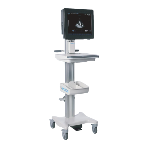
The ImaCor ZURA-EVO Imaging System includes an ultrasound machine optimized for use with the ImaCor ClariTEE probe (Figure 2). The machine contains a liquid crystal (LCD) touch screen and all the required system firmware and hardware except for the disposable ClariTEE probe. -
Page 16: Ultrasound Tte Probe
IMACOR ZURA-EVO IMAGING SYSTEM OVERVIEW Ultrasound TTE Probe The ZURA-EVO Imaging System TTE probe is provided as an optional for those instances where trans- thoracic imaging is the preferred method of cardiac imaging. The imaging modes available are identical to the ClariTEE: B-mode (2-D) and color flow. -
Page 17: Getting Started
GETTING STARTED Getting Started Preparing the System Plug the system into a hospital grade or equivalent receptacle (outlet). Connecting the Ultrasound Probe Locate the dedicated matching connector (ZIF connector) for the locking umbilical cable connector. Push the umbilical cable connector into place (Figure 7). The umbilical cable connector is large; you will need one hand to hold it and the other to turn the locking lever. - Page 18 GETTING STARTED Fig. 8 Remove the cover from the disposable probe Position the probe connector and handle as shown in Figure 9. Fig. 9 Position the probe connector and handle in hand Align the probe with the handle. Fig. 10 Align probe and handle Ver.
-
Page 19: Connecting Other Transducers
GETTING STARTED Insert the blue connector tab into the distal end of the handle (Figure 11). Fig. 11 Insert connector tab into distal end of the handle Gently press the probe connector over the handle; press the tab on the umbilical connector to assist with engagement (Figure 12). -
Page 20: Connecting The Ecg
GETTING STARTED Connecting the ECG Note: The ECG provided with the ZURA-EVO Imaging System is not for diagnostic purposes and is pro- vided only to assist the detection of images at end systole and end diastole. A three-lead ECG cable is provided for optional connection of the machine ECG to the patient. After con- necting the patient electrodes, connect the ECG cable to the machine using the circular twist-lock recep- tacle shown in Figure 14. -
Page 21: Turning The System On/Off
GETTING STARTED Turning the System On/Off Turn on the power supply by pressing the rocker switch at the bottom of the unit to the ON position, marked I. (The OFF position is marked O.) Fig. 15 Power switch Power up the computer by pressing the power button shown in Figure 16. Fig. -
Page 22: On-Screen Keyboard
GETTING STARTED On-Screen Keyboard Whenever alphanumerical input from the user is required, the ZURA-EVO Imaging System displays an onscreen keyboard, shown below. The keyboard is superimposed on the bottom of the patient informa- tion and imaging screens. Fig. 17 Onscreen keyboard Ver. -
Page 23: Imacor Ultrasound Imaging Software
IMACOR ULTRASOUND IMAGING SOFTWARE ImaCor Ultrasound Imaging Software Overview ImaCor Ultrasound Imaging Software v3.0.0 performs seven basic functions: 1. Recording and updating patient information 2. Real-time imaging 3. Cineloop acquisition 4. Cineloop enhancement 5. Cineloop playback 6. Cineloop evaluation 7. hTEE measurements: FAC, RV/LV, SVC Online Help System The complete User Manual is available electronically through the imaging software’s searchable Help... -
Page 24: Additional Help Resources
IMACOR ULTRASOUND IMAGING SOFTWARE Additional Help Resources Additional assistance in the form of tooltips and live technical support is also available. See page 97 for details. System Initialization See the Master Message Listing (page 110) for an explanation of system errors and suggested solutions. - Page 25 IMACOR ULTRASOUND IMAGING SOFTWARE Fig. 20 System initialization screen – animated transgastric short-axis flash card. Click the TGSAV, ME4CH, or SVC button to view the associated hTEE view. Fig. 21 System initialization screen – animated mid-esophageal four-chamber flash card. Click the TGSAV, ME4CH, or SVC button to view the associated hTEE view.
-
Page 26: Patient Information
PATIENT INFORMATION Patient Information Basic patient data are entered using the Patient Information window (Figure 23). After starting the Ima- Cor ZURA-EVO Imaging System, the Patient Information screen is the first interactive window displayed. Fig. 23 Patient Information screen, information editing enabled (see “Patient Information Screen Button Functions‚” page 27). Patient Information Screen Data Fields The fields detailed in Table 4 comprise the Patient Information screen. -
Page 27: Patient Edit Lock Feature
PATIENT INFORMATION Table 4 Patient Information Screen Data Fields (Continued) Field Name Status Function Notes Weight Optional Enter patient’s weight The drop-down menu to the right of the Weight field enables you to select Imperial or metric units. If you change units after entering the patient’s weight, the measurement is converted. -
Page 28: Patient List
The New Patient, Next, Configure, and Shutdown buttons are active but slightly dimmed. This is the default state of active buttons in the ImaCor system; it is intended to minimize visual distractions. The Sync button is enabled when a DICOM Archiving Server is active (see “Archiving Server Configura- tion‚”... -
Page 29: Dicom Synchronization Feature
If the MWL server query returns at least one item, you can import the information from a selected MWL item into the local patient record. See the DICOM Conformance Statement for details of imported fields. The DICOM Conformance Statement is available to registered customers for download from the ImaCor support web page: http://www.imacorinc.com/support.html Note: The accession number can be imported from the MWL server. -
Page 30: Synchronizing With A Dicom Archiving Server
Create a New Patient Record Access the Patient Information screen. – After starting the ImaCor ZURA-EVO Imaging System, the Patient Information screen is the first interactive window displayed. – If you are in the imaging environment, tap or click the Patient button. -
Page 31: Manually Select An Existing Patient Record
PATIENT INFORMATION – After starting the ImaCor ZURA-EVO Imaging System, the Patient Information screen is the first interactive window displayed. – If you are in the imaging environment, tap or click the Patient button. If a probe used in a previous patient exam is connected to the ZURA-EVO Imaging System, the sys- tem checks to see if data for the patient exists in the patient database. -
Page 32: Select A Patient Record Created On A Zura-Evo System
Access the Patient Information screen. – After starting the ImaCor ZURA-EVO Imaging System, the Patient Information screen is the first interactive window displayed. – If you are in the imaging environment, tap or click the Patient button. -
Page 33: Delete A Patient Record
Delete a Patient Record Touch Screen Access the Patient Information screen. – After starting the ImaCor ZURA-EVO Imaging System, the Patient Information screen is the first interactive window displayed. – If you are in the imaging environment, tap or click the Patient button. -
Page 34: Transferring Patient Records Between Imacor Zura/Zura-Evo Systems
Export a Patient Record to a Data Transfer Module (DTM) Access the Patient Information screen. – After starting the ImaCor ZURA-EVO Imaging System, the Patient Information screen is the first interactive window displayed. – If you are in the imaging environment, tap or click the Patient button. -
Page 35: Import A Patient Record From A Remote Zura-Evo System
ImaCor cine files as well as DICOM multiframe images. For more information, see “Configuring the System‚” page 91. • The ImaCor decryption utility must be used before DICOM images can be imported and viewed on a DICOM workstation. The decryption utility is available to registered customers for download from the ImaCor support web page: http://www.imacorinc.com/support.html... -
Page 36: The Imaging Environment
THE IMAGING ENVIRONMENT The Imaging Environment The imaging environment is where you will view, acquire, optimize, and compare real-time images and cineloops. There are two basic screen modes in the imaging environment: Single View and Split View: • Single View mode displays one real-time or cineloop view. For more information, see “Single View Mode, ”... - Page 37 THE IMAGING ENVIRONMENT Table 6 Single-View Imaging Screen Features Number Feature Function Notes Probe meter Displays the probe’s unique serial number and a progress bar indicating the time remaining on the probe (0–72 hours). Patient name Patient’s first and last name. Frame title Alerts user that real-time imaging is taking Indicates current view.
- Page 38 THE IMAGING ENVIRONMENT Table 6 Single-View Imaging Screen Features (Continued) Number Feature Function Notes Freeze/Unfreeze Toggle that starts or stops the acquisition of Freeze: Halts imaging on the last frame real-time images. viewed and internally saves the last 50 frames. The 50-frame buffer enables you to scroll backward to view previous frames.
- Page 39 THE IMAGING ENVIRONMENT Fig. 28 Single View mode layout buttons Table 7 Imaging Screen Buttons Number Feature Function Notes Probe The probe button displays status information about the probe currently in use. • User can select the ClariTEE probe or another;...
-
Page 40: Split View Mode
THE IMAGING ENVIRONMENT Table 7 Imaging Screen Buttons (Continued) Number Feature Function Notes Measure Displays Measure buttons that allow user to select Area, Distance, or Off option. Single/Split View Toggles between Single View and Split View See “Single View Mode‚” page 35 and “Split modes. - Page 41 THE IMAGING ENVIRONMENT Fig. 29 Split View mode imaging screen Table 8 Split View Imaging Screen Number Feature Function Notes Probe meter Displays the probe’s unique serial number and a progress bar indicating the time remaining on the probe (0–72 hours) Patient name Patient’s first and last name hTEE...
- Page 42 THE IMAGING ENVIRONMENT Table 8 Split View Imaging Screen (Continued) Number Feature Function Notes Grayscale Used in adjusting monitor brightness and The grayscale is a vertical gradient bar on the contrast imaging screen that allows the user to adjust the LCD’s brightness to an optimal setting for the ambient lighting.
- Page 43 THE IMAGING ENVIRONMENT Table 8 Split View Imaging Screen (Continued) Number Feature Function Notes Date and time Logo and institution name Ver. 2.3.2...
-
Page 44: Probe Selection
PROBE SELECTION Probe Selection The EVO and EVO 1 systems support both the ClariTEE and TTE probes. The Imaging window provides a probe dialog box for the user to select a probe. It displays information of the probes currently connected to either of the two connector ports in the back of the system. - Page 45 PROBE SELECTION – TTE 2.0 MHz – TTE 3.3 MHz Using the setting menu - Tap or Click the setting menu in the upper right corner of the screen. The “active” probe type is indicated by the tutorial button on the upper right corner of the screen. The setting menu list will reflect the “active”...
- Page 46 PROBE SELECTION Fig. 32 Setting menu list for TTE probe Ver. 2.3.2...
-
Page 47: Real-Time Imaging
REAL-TIME IMAGING Real-Time Imaging After leaving the Patient Information screen, you enter the imaging environment at the Single View screen. If a valid probe is connected, real-time imaging automatically begins. Figure 33 depicts real-time imaging in Single View mode. Real-time imaging can also take place in Split View mode; see “Split View Mode‚”... -
Page 48: Depth Markers
REAL-TIME IMAGING Depth Markers To display depth markers on a real-time ultrasound image: Touch Screen Tap anywhere on the screen and hold. Choose the Depth Markers option from the global context menu (see Figure 35). The interval between two adjacent depth markers is 1 cm. ZURA-EVO Imaging System Mouse Right-click anywhere on the screen. -
Page 49: Unfreeze
REAL-TIME IMAGING The 50-frame buffer enables you to scroll backward to review previous frames and select the best one captured around the time the freeze was requested. When scrolling, the fps rate displayed onscreen indi- cates the speed at which you are reviewing frames. Scrolling is accomplished by dragging the horizontal scroll bar to the right or left, depending on whether you wish to advance or review previous frames (see Figure 37). -
Page 50: Activating The Steering Feature
REAL-TIME IMAGING • At 15, 16, 17, and 18 cm, steering advances one step on either side of the image to ±4 degrees. • For a 90 degree sector: – From 6–14 cm, steering is three steps on either side of the image –... -
Page 51: Optimizing Real-Time Images
OPTIMIZING REAL-TIME IMAGES Optimizing Real-Time Images B-Mode Images The ZURA-EVO Imaging System provides a wide range of controls to optimize real-time B-mode images captured by the ultrasound hardware. • Gain control • Time Gain Compensation (TGC) • Auto-Q feature • Filter control •... -
Page 52: Time Gain Compensation (Tgc)
OPTIMIZING REAL-TIME IMAGES – Increase the gain value by dragging the gauge value bar to the right or by tapping/clicking the right arrow beneath the control. Fig. 39 Gain Control display Time Gain Compensation (TGC) TGC control is an index in a family of preset TGC curves. It simplifies the usual TGC slider controls. Since ultrasound waves are attenuated, or absorbed, as they pass through tissue, the waves reflected from distant areas are weaker than those from the areas near the transducer. -
Page 53: Filter Control
OPTIMIZING REAL-TIME IMAGES To activate the Auto-Q feature, tap or left-click the onscreen Auto-Q button during live imaging (Figure 41). Note: Image quality is subjective; you may prefer Gain and TGC settings other than those selected by Auto-Q. Fig. 41 Auto-Q feature Filter Control The Filter control is a despeckling (noise reduction) filter that enhances the contrast of the preprocessed ultrasound images. -
Page 54: Depth Control
OPTIMIZING REAL-TIME IMAGES Fig. 43 Contrast control display Depth Control The Depth control determines the depth in centimeters of the displayed image. The Depth control range is 6–18 cm for TEE and 6-25 for TTE. It is adjusted in 1 cm increments. The ZURA-EVO Imaging System automatically saves the last imaging depth for the selected patient and restores that depth when the patient is again selected for imaging. -
Page 55: B-Map Control
OPTIMIZING REAL-TIME IMAGES B-Map Control To change the B-map for better imaging quality, Tap or click the gray bar on the left side of the screen. The current B-map index number will be shown on the top of the gray bar with a range from 1 to 17. Focus Control To change the probe focus for better imaging quality, Tap or click inside the live imaging sector. -
Page 56: Reject Control
OPTIMIZING REAL-TIME IMAGES Fig. 46 Dynamic control Reject Control Reject range is the lowest echo signal in dB below which to discard. Tap or click the Controls button at the bottom of the screen to display the image quality controls. The Controls button acts as a toggle;... -
Page 57: Color Flow Images
OPTIMIZING REAL-TIME IMAGES Color Flow Images Color flow imaging quality is managed by two real-time image quality controls: CF Gain and CF Filter. B-mode controls continue to be available in CF mode. CF Gain Control Tap or click the Controls button at the bottom of the screen to display the image quality controls. The Controls button acts as a toggle;... -
Page 58: The Ecg Waveform
• ECG cursor • ECG markers The ImaCor ZURA-EVO Imaging System enables you to customize the ECG waveform display. The ECG waveform can be shown in both Single View and Split View environments. Fig. 50 Example ECG waveform with markers... -
Page 59: Adding An Ecg Marker
Choose the Delete ECG Marker option from the pop-up menu (see Figure 55). If you delete all ECG markers on a cineloop, the ImaCor System software will attempt to detect the R- wave peaks and place ECG markers accordingly the next time the cineloop is loaded. -
Page 60: Changing The Ecg Sweep Speed
THE ECG WAVEFORM ZURA-EVO Imaging System Mouse Right-click anywhere on the screen. Choose the desired ECG Lead from the pop-up menu (see Figure 53) Fig. 53 Change ECG lead option Changing the ECG Sweep Speed Touch Screen Tap anywhere on the screen and hold. When the pop-up menu opens, choose from the two sweep-speed options: 25 mm/s and 50 mm/s, as shown in Figure 55. - Page 61 THE ECG WAVEFORM Add ECG marker Delete ECG marker Change ECG Invert ECG sweep speed waveform Fig. 55 ECG menu options Ver. 2.3.2...
-
Page 62: Image Acquisition
IMAGE ACQUISITION Image Acquisition RELATED TOPICS Configuring the System | “Acquisition‚” page 92 “Deleting a Cineloop‚” page 70 Acquiring Images Real-time images and ECG data can be acquired and saved as a three-second cineloop. Images can be acquired in both Single View and Split View modes. Figure 56 shows the Single View imaging screen during acquisition. -
Page 63: Adding Comments To Cineloops
IMAGE ACQUISITION Fig. 56 Image acquisition – Single View mode Adding Comments to Cineloops While the cineloop is being saved to disk, you may enter a comment in the cineloop comment window. The Comment window appears as soon as the ZURA-EVO Imaging System begins saving the cineloop (see Figure 57). -
Page 64: Recovery Mode
Recovery mode allows the ClariTEE probe to cool. While the cineloop is being written to disk, the ImaCor ZURA-EVO Imaging System software enters a 3.3- second recovery mode to allow the probe to cool. During the recovery period, the acquisition function is disabled. -
Page 65: Managing Cineloops
MANAGING CINELOOPS Managing Cineloops Related Topics Configuring the System | “Acquisition‚” page 92 “Color Flow Imaging‚” page 86 “Synchronized Cineloop Playback‚” page 83 “Loading Two Cineloops in Split View Mode‚” page 81 “Viewing a Cineloop and Real-Time Images in Split View Mode‚” page 81 Loading a Cineloop From the Patient Information screen: –... -
Page 66: Reviewing A Cineloop
MANAGING CINELOOPS To assist with cineloop identification, the first 32 characters of the cineloop comment are displayed. Cineloops are also labeled with the date and time of acquisition and hTEE view type, if available. Locate the cineloop you wish to view. Tap or click once on the desired cineloop. -
Page 67: Color Flow Indicator Icon
MANAGING CINELOOPS Fig. 59 Single View mode with cineloop control buttons Color Flow Indicator Icon When Color Flow (CF) images are available for a cineloop, the CF indicator icon is displayed. Tap or click the CF indicator icon to toggle on and off the display of Color Flow images during cineloop playback and when viewing frozen real-time images. -
Page 68: Cineloop Image Quality Controls
MANAGING CINELOOPS Cineloop Image Quality Controls Cineloop image quality controls enhance existing loops for review purposes. Changes to the image con- trol settings are not saved with the cineloop. Brightness Control The Brightness control allows you to increase or decrease the brightness of your cineloop. Tap or click the Controls button at the bottom of the screen to display the image quality controls. -
Page 69: Contrast Control
MANAGING CINELOOPS Fig. 61 Depth brightness compensation control (DBC) display Contrast Control Tap or click the Controls button at the bottom of the screen to display the image quality controls. The Controls button acts as a toggle; press it again to clear the cineloop image quality control display. -
Page 70: Saving A Cineloop As A Movie
Cineloops can be exported as movies that can be viewed on standard video (.AVI and .MOV) players. Exported movies must be saved to a USB thumb drive. You need not use an ImaCor-formatted DTM for this operation. Cineloops are watermarked with the ImaCor logo. -
Page 71: Deleting A Cineloop
MANAGING CINELOOPS Fig. 64 Export movie format options Deleting a Cineloop You can store a maximum of 100 cineloops per patient. As you near a patient’s cineloop limit, warning messages are displayed, as shown in Figure 65. Fig. 65 Warning: cineloop limit approaching Once 100 cineloops have been saved, you cannot acquire additional images unless you overwrite the oldest loop or delete one or more cineloops. - Page 72 MANAGING CINELOOPS Fig. 67 Delete cineloop screen When the warning message appears, tap or click the Yes button to delete the cineloop or No to can- cel the operation. Once a cineloop has been deleted, it cannot be retrieved. Fig. 68 Delete cineloop confirmation Tap or click the Done button to exit Clean-up mode.
-
Page 73: Measurement Tools
MEASUREMENT TOOLS Measurement Tools The ImaCor ZURA-EVO Imaging System software provides two measuring tools: • The Tracing Tool, for area measurements. This tool is key when performing hTEE calculations: – FAC – RV/LV ratio – SVC collapsibility index Area measurement is the default measuring mode. -
Page 74: Deleting Points On A Trace
MEASUREMENT TOOLS ZURA-EVO Imaging System Mouse Right or left-click to set first anchor point and begin the trace. Use the mouse to draw the trace. When tracing, the mouse is set to a lower sensitivity to reduce trac- ing errors. Mouse speed can be customized in the in the Configuration dialog box (see page 91). A low speed number indicates low sensitivity;... -
Page 75: The Measuring Tape Tool
MEASUREMENT TOOLS To clear all distance and area measurements at once, tap or click the Clear All button. The Measuring Tape Tool The measuring tape tool can be accessed by tapping or clicking the onscreen Measure button and selecting Distance. The informational message “Measure: ON” is displayed on the screen. Fig. -
Page 76: Editing A Measurement
MEASUREMENT TOOLS If the end point of a measurement must begin on top of or very near another point: Touch Screen Create a second measurement. Drag and drop the point(s) to the desired location. ZURA-EVO Imaging System Mouse Move the cursor to the desired end point location and pause until the highlight on the neighboring point disappears. -
Page 77: Viewing Measurements On Cineloops
MEASUREMENT TOOLS Fig. 72 Single View mode with distance measurements (Measure: ON) If you turn off either trace or measure mode, both measurements are hidden. Reactivating one mode will display only the measurement associated with it. The second measurement can be turned on separately, if desired. - Page 78 MEASUREMENT TOOLS Tap or click the trend button to display the trending graph. The trend button changes to an OK but- ton. To close the trending graph, tap the OK button. Fig. 73 Trending button. The system collects existing measurements for the current patient and displays the trending curves on top of the Imaging screen.
- Page 79 MEASUREMENT TOOLS Fig. 74 Trending measurements. Ver. 2.3.2...
-
Page 80: Zura-Evo Htee Measurement Functions
ZURA-EVO IMAGING SYSTEM HTEE MEASUREMENT FUNCTIONS ZURA-EVO Imaging System hTEE Measurement Functions Related Topic “Loading a Cineloop‚” page 64 The ZURA-EVO Imaging System enables you to perform three types of hTEE measurements: • FAC (LVEDA, LVESA) • RV/LV ratio (RVEDA, LVEDA) •... -
Page 81: Reviewing An Htee Trace
ZURA-EVO IMAGING SYSTEM HTEE MEASUREMENT FUNCTIONS Fig. 75 Manually updating a trace value Reviewing an hTEE Trace To review an existing hTEE trace, click on the desired measurement (LVEDA, LVESA, RVEDA, SVCMin, SVCMax). The ZURA-EVO Imaging System software automatically displays the traced frame and high- lights the selected measurement. -
Page 82: Working In Split View Mode
WORKING IN SPLIT VIEW MODE Working in Split View Mode Loading Two Cineloops in Split View Mode Access the Split View screen. Tap or click the Load button. When the Load Loop window is displayed, select a loop from the left and one from the right pane, as shown in Figure 77. - Page 83 WORKING IN SPLIT VIEW MODE Fig. 78 Viewing a cineloop (left) and a real-time image (right) in Split View mode Fig. 79 Split View mode – cineloop comparison Ver. 2.3.2...
-
Page 84: Synchronized Cineloop Playback
WORKING IN SPLIT VIEW MODE Synchronized Cineloop Playback The synchronized playback function enables you to review a full cardiac cycle from two different cineloops in a synchronized fashion. You must view cineloops—the function is unavailable during real- time imaging—and each loop must have at least two ECG markers. The software synchronizes the playback using the first two consecutive ECG markers it encounters on each cineloop. -
Page 85: Synchronized Playback Speed Controls
WORKING IN SPLIT VIEW MODE Synchronized Playback Speed Controls During synchronized playback, the Forward and Back buttons act as speed controls. The Forward button increases the frame rate and Back slows the playback. Playback speeds are: 0.25, 0.5, 0.75, 1.0, 1.5, 2.0. To view a frame-by-frame synchronized playback, you must scroll on the master (right) side of the dis- play, as shown in Figure 80. - Page 86 WORKING IN SPLIT VIEW MODE Fig. 83 Split View mode with Compare ED/ES selected Ver. 2.3.2...
-
Page 87: Color Flow Imaging
COLOR FLOW IMAGING Color Flow Imaging Color flow (CF) imaging, also known as Color Doppler, uses color to detect blood flow and determine flow direction. Colors in the middle to the top of the Color Map indicate positive blood-flow velocities; i.e., blood flow toward the transducer. -
Page 88: Repositioning The Color Box
COLOR FLOW IMAGING Repositioning the Color Box Note: Changes to the position of the color box take effect in 1.5 seconds. Touch Screen With color flow imaging active, tap inside the color box. Drag the box to the desired position, or— With color flow imaging active, tap inside the color box. -
Page 89: B-Mode Priority
COLOR FLOW IMAGING B-Mode Priority B-mode priority is a user-adjustable grayscale value between 10 and 255. B-mode data takes priority when the grayscale value is greater (brighter) than the user-set priority value. For example, if you set a priority level of 150, B-mode data are shown instead of CF data when the B-mode data value is greater than 150. -
Page 90: Changing The Velocity Setting
COLOR FLOW IMAGING ZURA-EVO Imaging System Mouse Right or left click the velocity display (V Max) during Color Flow imaging. Fig. 87 Velocities menu Changing the Velocity Setting Velocity setting availability is associated with the depth of the color box. When the bottom edge of the color box exceeds 9 cm, the velocity setting automatically changes from High to Medium. -
Page 91: Color Maps
COLOR FLOW IMAGING Color Velocity Maps Five color maps are available. Fig. 88 Highlighted color map Changing Color Maps Touch Screen Tap the onscreen color map to advance to the next color map. ZURA-EVO Imaging System Mouse Left-click the onscreen color map to advance to the next color map. Ver. -
Page 92: Configuring The System
CONFIGURING THE SYSTEM Configuring the System The Configuration dialog window consists of seven tabbed sections: • General • Acquisition • Date-Time • DICOM • Language • Version • Help The Configuration dialog can be accessed from either the Patient Information screen or the imaging environment. -
Page 93: Measuring And Tracing Settings
CONFIGURING THE SYSTEM Measuring and Tracing Settings TRACE RESOLUTION Trace resolution is the interval between two consecutive anchor points. This interval is expressed in pix- els, so a smaller resolution value results in a larger number of anchor points. The range is 1–20. TRACE COLOR The Trace Color option enables you to specify anchor point color. -
Page 94: Date-Time
CONFIGURING THE SYSTEM Fig. 91 Configuration >Acquisition tab Date-Time The Date-Time tab enables you to set the current date and time. Changing the system date and time has no effect on probe life. Fig. 92 Configuration > Date-Time tab DICOM Digital Imaging and Communications in Medicine (DICOM) is the standard format for distributing and viewing all types of medical images. -
Page 95: Patient Export Options
DICOMDIR. • DICOMDIR and DICOM files are encrypted before they are saved onto a DTM. An ImaCor decryption application is provided to import DTM data into a DICOM workstation. -
Page 96: Custom Synchronization Rules
ID is not empty will be sent to the Archiving Server. The rules can only be turned ON/OFF by an ImaCor technician. If the Require Patient Accession Number rule is ON, cineloops are sent to the server only if the accession number field in the Patient Information screen is completed for the corresponding patient. -
Page 97: System
Enter the ZURA-EVO Imaging System machine registration code, which can found on the Version tab of the ZURA-EVO Imaging System Configuration window. Tap or click on the Go button. A license request is automatically sent to the ImaCor support team. Tap or click on the “Download File” option. -
Page 98: Upgrade The Zura-Evo Software
Remote Assistance The Remote Assistance button enables you to establish a link with an ImaCor technician who can access the ZURA-EVO Imaging System remotely for troubleshooting. Once the Remote Assistance button is clicked, the Support Internet Explorer window is displayed. -
Page 99: Analysis Package
— you may: – Reinsert the drive in the ZURA-EVO Imaging System. – Retry the operation. The error code shown in the message may vary and is for the use of ImaCor technicians only. Fig. 97 Analysis package export error Ver. 2.3.2... - Page 100 CONFIGURING THE SYSTEM If no USB drive is present when the Analysis Package button is pressed, the error message below is displayed. Ver. 2.3.2...
-
Page 101: Safety
• The ClariTEE probe is designed for single patient use only. If the probe is reused there are known char- acteristics and technical factors that could pose safety risks as follows: – The probe is not designed to survive Cydex disinfection. Cydex disinfection of the ImaCor ClariTEE probe could present a toxicological and electric shock risk to the patient –... -
Page 102: Applying Alara
Caution The ImaCor ZURA-EVO Imaging System should not be used beyond a maximum cumulative imag- ing time per patient of 6 hours. Normal use should consist of a maximum of six episodic assessments over a 24-hour period with maxi- mum intubation time (the probe dwells within the patient) not to exceed 72 hours. -
Page 103: Watchdog Monitor
• To reduce the risk of electrical shock, use only accessories and peripherals recommended or supplied with the system by ImaCor. Use of accessories and peripherals not recommended by ImaCor could result in electrical shock. Contact ImaCor or your local representative for a list of accessories and peripherals available from or recommend by ImaCor. -
Page 104: Biocompatibility Safety
SAFETY netic interference (EMI) in other devices in the vicinity. The ZURA-EVO Imaging System complies with IEC 60601-1-2 Collateral Standard: Electromagnetic Compatibility – Requirements and Tests. Medical electrical equipment requires special precautions regarding EMC and must be installed and operated according to these instructions. It is possible that high levels of radiated or conducted radiofre- quency electromagnetic interference (EMI) from portable and mobile RF communications equipment or other strong or nearby radiofrequency sources could result in performance disruption of the ultrasound system. -
Page 105: Global Maximum Derated Ispta, Mi, And Ti Values
SAFETY Note: Cardiac use includes transesophageal use for visualization of the heart. Global Maximum Derated ISPTA, MI, and TI Values ISPTA is the intensity, spatial-peak temporal-average defined as the value of the temporal-average state that ISPTA and MI are defined parameters in the FDA guidance document for ultrasound systems. TI is a temperature index defined in IEC60601-2-37, an internally recognized standard for ultrasound diagnostic equipment. - Page 106 SAFETY Table 13 Labeling Symbols and Descriptions (Continued) On (power: connection to the mains) “Off” (only for a part of EQUIPMENT “On” (only for a part of EQUIPMENT Type B equipment Type BF equipment Keep away from sunlight Keep dry Manufacturer Authorized representative in the European Community Sterilized using ethylene oxide...
-
Page 107: Imacor Approved Device
Data Transfer Module (DTM) ImaCor-supplied thumb drive for transferring image files, patient infor- mation, cineloops, and measurements. The drive is also used to export cineloops as DICOM files. Note: Only thumb drives provided by ImaCor can be used. General purpose thumb drives will not func- tion with the ImaCor ZURA-EVO Imaging System. -
Page 108: Troubleshooting And Maintenance
1. Check ECG connection on machine 2. Check patient ECG lead connections Maintenance ImaCor Inc. offers a preventive maintenance plan. Contact ImaCor for further information. The following user maintenance is recommended. ZURA-EVO Imaging System Cleaning Recommendations ImaCor recommends the following cleaning instructions for the ZURA-EVO Imaging System. -
Page 109: Lcd Monitor Cleaning
TROUBLESHOOTING AND MAINTENANCE Caution • The ClariTEE probe is for single use only and is to be disposed after single use. • To reduce the risk of electrical shock, always disconnect the power supply from the system before cleaning the system LCD MONITOR CLEANING Turn off the system prior to cleaning the touch screen. -
Page 110: Other Recommended Maintenance
TROUBLESHOOTING AND MAINTENANCE Other Recommended Maintenance POWER SUPPLY CORD Regularly inspect the AC power cord and plug for damage. HANDLE AND UMBILICAL Regularly inspect the handle and umbilical for damage. Warning: Do not actively connect to a patient while performing maintenance on any part of the system. -
Page 111: Master Message Listing - Alphabetical
OK button. between the local data (that This will append the informa- saved on the ImaCor ZURA-EVO tion being transferred from the Imaging System) and the DTM. DTM to the patient record on the local system. - Page 112 Also, verify that the server allows communications from the ZURA-EVO Imaging System AE. The system isn’t communicating Click the OK button and restart with the patient database. the system. If the problems persists, contact ImaCor technical support. Ver. 2.3.2...
- Page 113 Click the OK button and restart for the specific error. the system. If the problems persists, contact ImaCor technical support. The Unfreeze or Acquire button 1. End the exam. was pressed while an invalid 2. Connect a valid probe, or–...
- Page 114 A probe is not connected to the Connect a probe and select it system. with the Probe button. The ImaCor system is designed to No immediate action is necessary. store a maximum of 100 For more information, see Deleting cineloops per patient. This infor- a Cineloop, page 70.
- Page 115 • Continue current exam; how- ever, imaging functions will be disabled The connected probe has been The ImaCor ZURA-EVO Imaging used for more than 72 hours. The System can be used to review the message includes the date the patient’s recorded cineloops, but probe was first used.
- Page 116 MASTER MESSAGE LISTING - ALPHABETICAL Problem Solution Informational message. The data transport module is properly con- nected, enabling patient data import and export functions. A record has been created for a 1. Move the cursor to the first new patient, but the patient’s first name field name hasn’t been entered.
- Page 117 The machine will shut- down in the specified number of seconds. 1. An ImaCor update package Obtain and run a valid ImaCor has been corrupted, or– update package. 2. You have attempted to run another executable as if it were an ImaCor update package.
- Page 118 Or, while examining a patient, you return to the patient information screen and create a new patient record. The ImaCor system is designed to Delete one or more cineloops. store a maximum of 100 For more information, see Deleting cineloops per patient. You have a Cineloop, page 70.
-
Page 119: Maintenance And Cleaning Of Tte Probe
MAINTENANCE AND CLEANING OF TTE PROBE Maintenance and Cleaning of TTE Probe Transducers Overview • Read all documentation accompanying the transducer. Make certain you are familiar with the proce- dures for using, maintaining, and cleaning the transducer. • Always follow the manufacturer’s instructions on cleaning and disinfection procedures. •... -
Page 120: Disinfecting Noninvasive Transducers
MAINTENANCE AND CLEANING OF TTE PROBE Warning: • Do not use sterilize using an autoclave, ultraviolet, gamma radiation, gas steam, or heat sterilization techniques. • Do not clean or disinfect with phenol, benzothonium chloride, pHisohex, hydrogen peroxide, ben- zoyl peroxide, acetone, freon, or other industrial cleansers. Use only chemicals or cleaning agents recommended by the manufacturer. -
Page 121: Storing And Packaging
MAINTENANCE AND CLEANING OF TTE PROBE Storing and Packaging To help avoid contamination, ensure the transducer is clean/disinfected and dry before storing and/or packing it. Store transducers: • in one of the transducer holders • separately, in a protected environment to avoid inadvertent transducer damage •... -
Page 122: References
535). Areas were calculated based using the height and width measurements and based on the area formula for an ellipse (A = hw/4). The control data used as the basis for the ImaCor ZURA-EVO Imaging System measurement accuracy determination were the mean height and width measurements, along with the calculated areas of three predicate systems combined. - Page 123 REFERENCES Table 17 Accuracy of Distance Measurements and Area Calculations Height (cm) Width (cm) Area (cm Transducer (measured) (measured) calculated Comments * Assumes that the control data averages of 15 measurements by the three predicate systems, represent the actual dimensions. Does not include rounding or monitor limitations.
- Page 124 REFERENCES Table 19 Test Results (Area) Parameters Area (AREA) (cm) AREA 1005.97 AREA 0.01 Ver. 2.3.2...
-
Page 125: Specifications
SPECIFICATIONS Specifications Table 20 ImaCor System Specifications Item Specification System dimensions Content Display dimensions 19-inch LCD display Transducers (probes) Phased array Single-use, disposable, provided sterile Multi-use Imaging mode Type B mode imaging Color Flow mode imaging Sector Angle 70° and 90°... -
Page 126: Glossary
GLOSSARY Glossary Terms ClariTEE™ ImaCor miniature disposable TEE probe Cineloop Recorded ultrasound image file Fractional area change Change in ventricular area at end diastole to end systole Intensive Care Unit ImaCor ZURA-EVO™ ImaCor ZURA-EVO Imaging System First upward deflection of the electrocardiogram... - Page 127 GLOSSARY Left ventricular Left ventricular end-diastolic area LVEDA LVESA Left ventricular end-systolic area Mechanical index Radiofrequency interference Transesophageal echocardiography Time gain compensation TGSAV Trans-gastric short-axis view Transthoracic echocardiography Universal serial bus Zero insertion force Ver. 2.3.2...
Need help?
Do you have a question about the ZURA EVO and is the answer not in the manual?
Questions and answers