
Related Manuals for AUTOTERM AIR-4D 12V/24V

Summary of Contents for AUTOTERM AIR-4D 12V/24V
- Page 1 Operation manual Simple control for air heaters AIR-2D 12V/24V AIR-4D 12V/24V AIR-8D 12V/24V AIR-9D 12V/24V v01.2018...
-
Page 2: Table Of Contents
Using the control panel ......................4 Installation of the control panel ..................... 5 Operating modes ........................5 Features of operating modes ....................6 Malfunctions .......................... 9 Manufacturer: AUTOTERM LLC Paleju 72, Marupe, Latvia, LV-2167 Warranty Department warranty@autoterm.com Technical Support service@autoterm.com www.autoterm.com... -
Page 3: Introduction
If you have any concerns, we strongly recommend that you contact the authorized service centers, the addresses and phone numbers of which you can obtain from the seller or on the website www.autoterm.com Before operating the product, read this operating manual and the heater operating manual. -
Page 4: Simple Control Panel
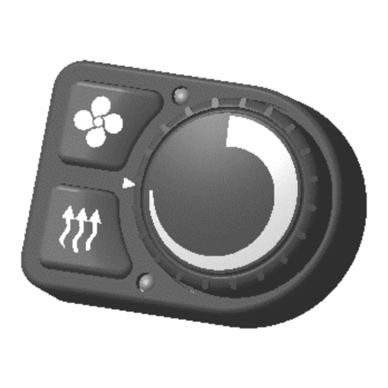
Simple control panel The following are located on the front of the panel: 1 – Ventilation mode on/off button; 2 – Heater on/off button; 3 – Operation LED display; 4 – Ventilation mode LED display; 5 – Potentiometer knob. The LED in Pos. 3 indicates the heater status: - yellow light - heating mode;... -
Page 5: Installation Of The Control Panel
Installation of the control panel - Apply a marking (see. Fig.1) on a surface for installation of the control panel (a hole for a harness and a hole for the self-tapping screw). - Pull and dismantle the potentiometer knob. Before dismantling the potentiometer's knob remember orientation of the knob relative to the mark on the control panel. -
Page 6: Features Of Operating Modes
Features of operating modes In case of “power” control mode is selected, the heater operates continuously with selected heat output. When a comfortable temperature is reached, we recommend to reduce power, ventilate the space or to switch off the heater. ... - Page 7 Control operation diagram...
- Page 8 Control operation diagram...
-
Page 9: Malfunctions
Malfunctions Malfunctions occurring during heater operation are coded and automatically displayed on the control panel by blinking of the red LED in pos. 4 (with pause). For malfunction reset, press any key. ATTENTION! Maintenance and repair should only be performed by trained, qualified personnel! The user can correct the following malfunctions (Table 1). - Page 10 Number Comments Malfunction description of blinks Troubleshooting Check the battery, the voltage regulator and power supply Shutdown due to wiring. Voltage between contacts 1 and 2 of power overvoltage connector should not be higher than 30 V (not higher than 16 V for 12 V product).
- Page 11 Table 2 Number Malfunction description of blinks Glow plug fault Flame detector fault Open circuit of the heat-exchanger shell temperature sensor Only for AIR-2D type air heaters Malfunction of control unit integrated temperature sensor Fuel pump fault Air blower fault. Speed of fan is lower than rated. The motor does not rotate.
Need help?
Do you have a question about the AIR-4D 12V/24V and is the answer not in the manual?
Questions and answers