Table of Contents
Advertisement
Quick Links
Advertisement
Table of Contents

Summary of Contents for Locosc LP-7515
- Page 1 LP-7515 INDICATOR USER’S MANUAL...
-
Page 2: Table Of Contents
TABLE OF CONTENTS Safety Precautions Preparations and Set Up Features Specifications Power Supply Displays Display and Key Descriptions Operating Instructions Calibration Indicator Parameter Settings Troubleshooting Connectors RS232 Serial Output Format Specifications... -
Page 3: Safety Precautions
SAFETY PRECAUTIONS For safe operation of the weighing indicator, please follow these instructions: ● Calibration inspection and maintenance of the indicator are prohibited by non- professional staff ● Please ensure that the indicator rests on a stable surface ● The indicator is a piece of static sensitive equipment; Please cut off power during electrical connections ●... -
Page 4: Features
FEATURES ● Smooth indicator shape with steady performance PCB board, is suitable for industrial or commercial use ● Multiple weighing units: (lb/oz/kg) ● Gross/Tare/Zero ● Low power design, longer battery usage time ● Hold function, locks the weight ● Idle mode and automatic power off function ●... -
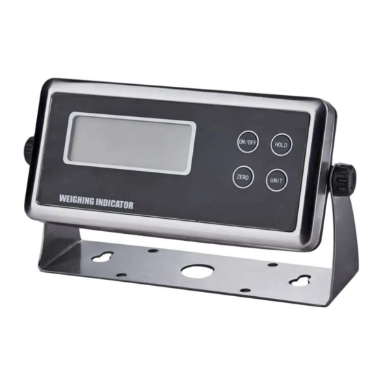
Page 5: Displays
DISPLAY AND KEY DESCRIPTION Weighing Mode Parameter Setting ON/OFF Powers the Indicator On or Off if held for 2 seconds Exit HOLD 1. Peak hold - Grabs the highest weight 2. Data hold - Holds the current weight value Confirm 3. -
Page 6: Operating Instructions
OPERATING INSTRUCTIONS Powering On or Off ● Press ON/OFF key for 1 second to power on. Machine will self inspect and count 1 - 9 from before entering weighing mode and displaying 0 ● Press ON/OFF key for 1 second to power off ●... - Page 7 ● While weighing, press HOLD and the indicator will hold the current weight on the screen until HOLD is pressed again 3. Auto Hold: If the weight on the scale is above 20d and is stable, the indicator will hold that weight on the screen for 3 seconds then go back to general weighing ●...
-
Page 8: Calibration
CALIBRATION To Enter Calibration Settings ● Turn indicator off. Then press and hold the HOLD and UNIT key simultaneously while the indicator is turning on (Do this while indicator is counting down) ● The display will show [ kg], meaning the unit is kg ●... - Page 9 CALIBRATION cont. If FS = 6 Please follow the procedure below: dP 1 ● The display will show [ ], to indicate how many decimal places you want; press UNIT to change, and press HOLD to confirm (ex. DP 2 = ####.##) ●...
-
Page 10: Indicator Parameter Settings
PARAMETER SETTINGS Function ● Press HOLD and UNIT together to enter the ON/OFF Exit parameter settings HOLD Confirm ● Use the following diagram to navigate through the ZERO Move Left parameter settings: UNITS Move Down Function Display Parameter Settings Automatic 0 = turn off auto power off OFF 10 Power Off... - Page 11 Negative Range (% 0 = -20d negative display nEgr 1 it can go negative 1 = 10% MAX negative display before an error) 2 = 100% MAX negative display Communication Set the serial interface data output method: trn 1 Setting 0 = Turn off serial interface data output 1 = Continuous sending mode, connect computer 2 = Print mode, connect printer...
-
Page 12: Troubleshooting
Zero Range: % of the max capacity that the scale is allowed to zero, anything above this percentage number will be tared. Initial Zero Range: The percentage of weight allowed on the scale when indicator is powered on that will automatically zero (anything above this percent will be tared). example: If initial zero range is set to 10% of the max. -
Page 13: Connectors
CONNECTORS Connecting load cells to the indicator ● The indicator can connect with 4 load cells of 350Ω at most. Use the quick disconnect connector Quick Disconnect DB9 Connection (9 pin Serial Connector) The DB9 9 pin serial connector is used for different purposes depending on the indicator model ●... -
Page 14: Rs232 Serial Output Format
DB9 SERIAL CONNECTOR PINOUT DB9 Pin Description DB9 Pin Definition Function Transmit Data Receive Data Ground Interface COMMUNICATION MODES Continuously send mode: the indicator continuously sends the data to the RS232 port Manually send mode: Press UNIT for 1 second to send the current data to the RS232 port Command Send Mode: From a computer send ASCII R character (hexadecimal 52) to the indicators RS232 port and the indicator will respond with the current data... -
Page 15: Specifications
ST, GS+ 5.12KG ST = Stable GS = Gross + = Weight is positive 5.12 = Weight KG = Unit measurement SPECIFICATIONS...