Table of Contents
Advertisement
Quick Links
ELECTRIC MINI ATV
E-ZR50
OWNER'S MANUAL
Read and understand this entire manual before using!
NOTE: Manual illustrations are for demonstration purposes only.
Illustrations may not reflect exact appearance of actual product.
Specifications subject to change without notice.
OFF ROAD USE ONLY!!!
NEVER OPERATE THIS VEHICLE IF YOU ARE UNDER
AGE 12!!!
- 1 -
Advertisement
Table of Contents

Summary of Contents for LIYA E-ZR50
- Page 1 ELECTRIC MINI ATV E-ZR50 OWNER’S MANUAL Read and understand this entire manual before using! NOTE: Manual illustrations are for demonstration purposes only. Illustrations may not reflect exact appearance of actual product. Specifications subject to change without notice. OFF ROAD USE ONLY!!!
-
Page 2: Safety Warnings
INTRODUCTION Thank you for purchasing this mini ATV. The proper care and maintenance that your vehicle requires is outlined in this manual. Following these instruction will ensure a long trouble-free operating life of this vehicle and your satisfaction with it. The owner’s manual corresponded to the latest state of this vehicle at the time of printing. - Page 3 Keep this product away from small children younger than age 12 and remember that this product is intended for use only by persons who are, at a minimum, completely comfortable and competent while operating the vehicle. 145LBS ( 65KGS) . Rider weight does not necessarily DO NOT EXCEED THE WEIGHT LIMIT OF mean a person’s size is appropriate to fit or maintain control of the mini ATV Do not touch the brakes or motor on your vehicle when in use as they can become very...
- Page 4 A long-sleeved shirt, long pants and gloves are recommended. Always wear athletic shoes, never drive barefooted or in sandals, and keep shoelaces tied and out of the way of the wheels, motor and drive system. USING THE CHARGER The charger supplier with the vehicle should be regularly examined for damage to the cord, plug, enclosure and other parts, and in the event of such a damage, the bike must mot be charged until the charger has been repaired or replaced.
- Page 5 Sticker A as below is located on the left front fender. Sticker B as below is located on the right front fender Sticker C as below is located on the right front fender Sticker D as below is located on the left front fender. - 5 -...
-
Page 6: Before You Begin
Sticker E as below is located on the rear swing arm Sticker F as below is located on the chain cover LOCATION OF PIN PIN is stamp marked on an aluminum plate that is riveted on the rear swing arm PIN means the Product Identify Number which is unique for each unit. - Page 7 Some tools may be supplied; however, we recommend the use of mechanic’s grade tools. Use the supplied tools only as a last resort. The list of tool required is as follows: ·Open end wrench 10mm / / 24mm 13mm-15mm / 14mm-17mm ·Allen wrench 5mm / 6mm / 10mm·Bicycle style tire pump with pressure gauge Assembly illustration and instruction ASSEMLY REAR WHEEL...
- Page 8 ASSEBMLY TIE ROD A :Bolt M8*30 2pcs B: Spring waher Φ8 2pcs C: Tie rod left and right 2pcs D: Waher Φ8 2pcs E: Nut N8 2pcs 1. Align the hole of tie Spring waher (B), tie rod end ball (C), Waher (D) in sequence. 2.
- Page 9 ASSEMBLY HANDLEBAR WARNING: Failing to properly adjust and tighten the bolts that affix the handlebars can cause you to lose control and crash. A: Bolt M8×50 4pcs B: Upper Clamp C: Bottom Clamp D: handlebar cover E: Handle bar 1. Put the bottom clamp(C) on the steering rod plate with the screw hole in alignment, and place the handlebar (E) in the bottom clamp, then cover the upper clamp (B) on the...
-
Page 10: Inflating The Tires
Inflating the Tires NOTE:The 6” rear tires are inflated when shipped, but they invariably lose some pressure between the point of manufacturing and your purchase. Always inflate the tires to the correct PSI before first time use. Please read the specification sheet to get the information of tire pressure. Using a bicycle-style tire pump to inflate the tire to the PSI indicated on the sidewall of the tire. - Page 11 2-FUNCTION ADJUSTABLE SWITCH The 2-function adjustable switch is located under the seat ( see above picture). There are 2 letters standing for the different functions as follows, Throttle response is adjustable from 0.2S to 1S in clockwise rotation Top speed is adjustable from 8KM /H to 28KM/H in clockwise rotation OPTIONAL PART ---REMOTE CONTROL The remote control unit ( No.1 in above picture) is located under the seat, and the switch Stop the motor: press the button...
-
Page 12: Technical Specification Sheet
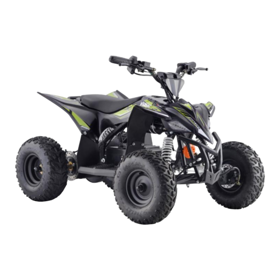
TECHNICAL SPECIFICATION SHEET Motor type 1 1000W 36V Motor type 2 1500W 48V MAX. Power output 1000W36V 1.08KW/2500RPM MAX. Power output 1500W48V 1.62KW/2950RPM Max torque (1000W motor) 3.22Nm /2500RPM Max torque (1500W motor) 5.48Nm/2780RPM 3 x 12V 12A lead acid battery Battery 48V10A / 48V 13A lithium battery Charger INPUT for 36V lead acid battery... - Page 13 PRODUCT MAIN PART DIAGRAM - 13 -...
- Page 14 Handlebar cover Front brake lever Electricity volume meter Throttle Rear brake lever Rear wheel & tire Front swing arm Bumper Front brake caliper 10. Front wheel & tire 11. Front lamp ( L& R) 12. Key ignition 13. Reverse button switch 14.
-
Page 15: Before Riding
BEFORE RIDING Charging the Battery Your electric mini ATV may not have a fully charged battery; therefore it is a good idea to charge the battery prior to use. · Initial charge time: 12 hours · Run time: up to 45minutes ·... - Page 16 How to charge the battery and change the fuse. The fuse is pre-fitted by the factory into your battery pack. Before you use the vehicle for the first time you will need to connect the power lead to the battery pack. Once you have connected, connect your charger to the charge point on the removable battery pack and Charge the quad for 10 hours before the first use.
- Page 17 3) Once you have removed the 6 screw,please carefully remove the top of the battery casing (Please be aware there are electrical cables connecting the top section of the case to the batteries in the lower section) 4) Locate the fuse holder within the battery pack. This is normally glued to the underside of the battery pack lid.
-
Page 18: Adjusting The Brake
5) Open the fuse holder and remove the fuse and replace with your spare fuse. Reverse the procedure to refit the battery pack. PRE-RIDE CHECKLIST ❑ Loose Parts Check and secure all fasteners before every ride. Make sure steering stem clamp bolts are locked properly in place. -
Page 19: Repair And Maintenance
REPAIR AND MAINTENANCE ❑ Adjusting the chain 1 . loosen the 4pcs nut (B) 2 . loosen the screw (A) and press the plastic buckle to remove the chain cover. 3 . loosen the chain adjuster nut (C), adjust the chain properly ( refer to the standard: chain can move freely up and down about 4mm), then fasten the nut (C) and (B) -
Page 20: Battery Care And Disposal
❑Chain and Sprocket The chain will typically have a “loose spot” and “tight spot” corresponding with a particular sprocket rotational position. This is normal and common to all chain-driven vehicles due to run-out tolerances of the freewheel and sprocket. Proper chain alignment must be maintained. If the chain is noisy or rough running, check the lubrication, tension and alignment of the sprockets, in that order. -
Page 21: Troubleshooting Guide
TROUBLESHOOTING GUIDE Problem Possible cause Solution Charge the battery. A new battery should have been charged for at least 12 hours before using the vehicle for the first time and up to 8 hours after each subsequent use. Undercharged battery. Check all connectors. - Page 22 Driving conditions Use only on solid, flat clean and dry Surfaces such as pavement or stressful. level ground. The tires are inflated when shipped, but They invariably will lose Tires are not properly Inflated. some pressure Between the point of manufacturing and your purchase.
-
Page 23: Circuit Diagram
CIRCUIT DIAGRAM - 23 -... - Page 24 Please read the owner’s manual before riding. Never operate this vehicle if you are under age 12. Never use the vehicle on public road. OFF ROAD use only. Never ride with a passenger Always use an approved helmet and protective gear NEVER use with drugs or alcohol Cold tire pressure.