Table of Contents
Advertisement
Quick Links
技术
要求
1 .
纸 张边角应 裁 剪整齐;
2 .纸质为
8 0g /m
;
3 .未注公 差按
GB/T1 80 4-c
4 .版面为 5;
A
5 .颜色要 求 黑色
:
K10 0
GG.2308-0454
C
GG.2307-0864
B
更改 文件 号
版 次
设 计
郑圣 鹏
校 对
潘卫琼
审 核
杨 瑞
说 明 书技 术要 求
印 刷字迹清晰 整洁、
级;
;
郑圣鹏
230811
郑圣鹏
230718
日 期
签 字
崔 中良
工 艺
标准 化
林 东运
批 准
刘 健
内容 正确
, 没有明显 的 拖墨和重影等缺陷 ;
TCC-24CHRH/DVI(02)
变频天花机说明书
A5纸
第 1 张
共 1 张
85008-008702
阶段标记
比例
质量
广东 智能暖通设备有限公司
Advertisement
Table of Contents

Related Manuals for Yamato YC12T1/I


Summary of Contents for Yamato YC12T1/I
- Page 1 说 明 书技 术要 求 技术 要求 纸 张边角应 裁 剪整齐; 印 刷字迹清晰 整洁、 内容 正确 , 没有明显 的 拖墨和重影等缺陷 ; 2 .纸质为 8 0g /m ; 3 .未注公 差按 GB/T1 80 4-c 级; 4 .版面为 5; 5 .颜色要 求 黑色 K10 0 ;...
- Page 2 INVERTER YC12T1/I, YC12T1/O, YC12T1/P YC18T1/I, YC18T1/O,YC18T1/P YC24T1/I, YC24T1/O,YC24T1/P YC42T1/I, YC42T1/O, YC42T1/P YC48T1T/I, YC48T1T/O, YC48T1T/P YC55T1T/I, YC55T1T/O, YC55T1T/P...
- Page 3 Safety Notice The air conditioner is charged with inflammable refrigerant R32. Before using the air conditioner, please first read the instruction manual. Before installing the air conditioner, please first read the instruction manual. Before repairing the air conditioner, please first read the technical service manual. Compared with common refrigerant, R32 is an environmental-friendly refrigerant that has no harm to the ozone layer and weak greenhouse effect.
- Page 4 -------------------------------------------------------------------------------------- ----------------------------------------------------------------- --------------------- -------------------------------------------------------------------------------- ------------------------------------------------------ ---------------------------------------------------------- ----------------------------------------------------------------------- ----------------------------------------------- ------------------------------------------------- --------------------------------------------------------------------------- ----------------------------------------------- -------------------------------------------- ------------------------------------------------------------------------ --------------------------------------------------------------------------...
- Page 5 PRECAUTION Read the following " PRECAUTIONS" carefully before installation. The caution items stated here must be followed because these important contents are related to safety. The meaning of each indication used is as below. Incorrect installation due to ignoring of the instruction will cause harm or damage, and the seriousness is classified by the following indications.
- Page 6 Outdoor air temperature is below -15 Outdoor air temperature is over 50 Outdoor air temperature is below -15 Features of HEATING mode Preheat 2-5 minutes are necessary to preheat the indoor heat exchanger at the beginning of "HEATING" operation, lest cold air be discharged. Defrost In "HEATING"...
-
Page 7: Parts And Functions
PARTS AND FUNCTIONS Indoor Unit Outdoor Unit Requirements The air conditioner cannot be started up until it is powered on for 2 hours. Furthermore, in case of a shutdown lasting for about one diel only, please do not cut off the electricity supply. (it is necessary to heat the crankcase heater so as to avoid force start of compressor. - Page 8 FUNCTION AND OPERATION OF PANEL'S PARTS Please adjust room temperature properly especially when the old men, children, patients stay at house. Lightning and other electromagnetic radiation may cause ill effect .If it is ,please plug off the power switch ,and replug in ,then restart the unit. Do not block the inlet of indoor unit or outlet of oudoor unit, any of blocks will reduce cooling or heating efficiency.
-
Page 9: Display Panel
DISPLAY PANEL Infra red signal receiver: receive the signal from the remote controller. To make your remote controller operation more efficient, please let remote controller emitt or aim at infrared signal receiver. Buzzer: firstly power supplied or any of remote controller operations will make the buzzer sound once. -
Page 10: Indoor Unit Installation
INDOOR UNIT INSTALLATION Please select the space to install indoor unit according to the dimension show ( above,then install correctly,and have enough space for maintenance. ) Select installation location considering piping and wiring connection after the Indoor Unit has been hanged. Then decide the piping wiring leading direction. Be sure to lead the refrigerant pipes, drain pipes and connection wires out to its connection location before hanging the unit if the opening on the ceiling has been decided. -
Page 11: Installation Locations
Height description of the body dimensions Unit mm : 12/18K 130~135 130~135 130~135 175~180 175~180 175~180 175~180 INSTALLATION LOCATIONS CAUTIONS 1.Location in the following places may cause malfunction of the machine. (If unavoidable, please consult your local dealer) a. A place where there is flammable gas leakage. b. -
Page 12: Installation Space
INSTALLATION SPACE Above Above Above 270cm 100cm 100cm Ceiling Obstacle A>330mm Wall Fire-proof material material or other nonflammable Flammable Fire-proof materials other than material structure metal Up(B) Above 5cm Above 5cm Above 5cm Sides(C) Above 100cm Above 100cm HEIGHT BETWEEN CEILING AND FLOOR The installation height between ceiling and floor must be 2.7m~3.2m. - Page 13 New Concrete Bricks Wooden construction Inlaying or embedding the screw bolts. Put the square timber over the roof beam, then install the hanging screw bolts. Timber over the beam Blade shape Slide insertion insertion Roof beam Steel bar Ceiling Embedding screw bolt (Pipe hanging and embedding Hanging Screw Bolt...
-
Page 14: Panel Installation
PANEL INSTALLATION Panel installation should be done after piping and wiring. Be sure that the indoor unit and ceiling hole installation size is right before installation. CAUTION Be sure to seal the connection parts between the panel the ceiling and the panel - the indoor unit ,or even small gaps may cause wind/water leakage or condensing water. - Page 15 Flexible Hose Measure diameter of the hard pipe using cutting method, and adjust the joining angle. Pull out the flexible hose, do not over deform than illustrated below. Be sure to bind it with the attached band. Please place the flexible hose horizontally. Core shift adjustment Hose band Bend 45 C(Maximum)
- Page 16 Drainage Upward To make sure that the drainage pipe would not be slanted downward, lead it upward to a height 360mm maximum, then downward lead it. Below 100mm Indoor Unit Ceiling Drainage Test Check whether the drain pipe is unhindered before testing. 1) Stow water from sprue to check.
-
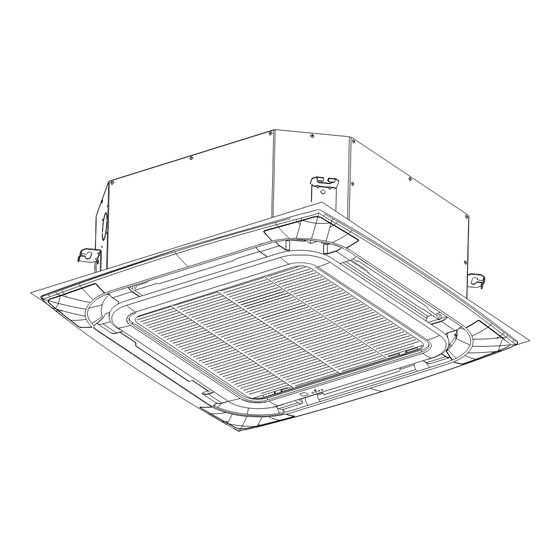
Page 17: Installation Of Panel
INSTALLATION OF PANEL BODY DIMENSION: Unload air-in grille Take off air-in grille Unload panel installation cap INSTALLATION OF PANEL 1.Please screw M10 gasket and M6*20 bolt at the corner of indoor unit, before screwing them fasten,screw other two additional bolt swhich locatesred bolt showin gas figure and notice that the direction of red arrow on theelectrical box aligns the one on the panel. - Page 18 BODY DIMENSION:580X255X580 Unload air-in grille Take off air-in grille ON/OFF Installation bolt hole INSTALLATION OF PANEL 1.Please screw M10 gasket and M6*20 bolt at the corner of indoor unit ,before screwing them fasten ,screw other two additional bolts which locates red bolt showing as figure and notice that the direction of red arrow on the electrical box aligns the one on the panel.
- Page 19 Figure of body size Split type outdoor unit Unit: MODE 12/18K 1010 660 1010 660...
-
Page 20: Outdoor Unit Installation
OUTDOOR UNIT INSTALLATION Move outdoor unit in Steel bar 1.Please use 4 pieces of 6mm steel wire hanging the outdoor unit up and Baffle move in. 2. To avoid the outdoor unit is out of shpe, please add the baffles at the surface of outdoor unit where the steel wire rope may touch. -
Page 21: Installation
INSTALLATION Pre-installation precautions Please confirm that the installation personnel are qualified in relevant installation service. If the air conditioner was installed by persons without special skills, normal operations would not be ensured, even the personal and estate safety would be affected. User guideline The user's installation site should be provided with regular power supply in conformity with that indicated in nameplate of the air conditioner, and its voltage should be within a range 90 %... -
Page 22: Refrigerant Pipe Installation
REFRIGERANT PIPE INSTALLATION Pipe dimension and ways of installation Outdoor pipe dimension and ways of install (in sequence of cooling capacity ) Pipe Material Copper Pipe for Air Conditioner 30/36/42/48/55K 12/18K Model Liquid side 9.52(5/8inch) 6.35(7/16inch) 6.35(7/16inch) Size(mm) ... - Page 23 FlARING Junction fixture Aim at connection pipe Cut the refrigerant pipr off with pipe cutter. fix the nut of connection pipe, then tighten] as the following diagram with spanner slant roughess Burr Notice According to installation conditions, overlarge wrenched torch will destroy the nut. (Unit. N.cm) Flaring after putting the pipe into connection nut.
- Page 24 The following figure only shows the assembly relationship of the indoor unit ,outdoor unit and refrigerant pipes. Please refer to the following figures to install. The throttle subassembly been installed in the outdoor unit.. Use two spanners to connect the pipe with indoor/outdoor pipes to avoid the copper pipe cracking. Please pay attention to the connection orientation when connecting.
-
Page 25: Electric Wiring
ELECTRIC WIRING WARNING Specified power cables should be used. Do not apply any pressure on the terminals used to connect. Improper connection may cause fire. Grounding must be properly done. The grounding wire should be away from gas pipes, water pipes, telephone, lightening rods or other grounding wires. - Page 26 Steps of external wiring connection 1. Remove air intake grille and electric box cover of indoor unit. 2. Remove access door of outdoor unit. 3. Connect the power supply connecting cablethe control connecting cable and defrostconnecting cable between indoor and outdoor unit.Please refer to the following pages for details.
-
Page 27: Indoor Unit
48/55K 3*1.0mm POWER SUPPLY INDOOR UNIT B A E 3*0.5mm (Signal cable with shield) L1 L2 L3 L3 B A E OUTDOOR UNIT POWER SUPPLY 5*2.5mm... - Page 28 TEST RUN Before testing a. Check if piping, drainage and external wiring have been finished correctly. b. Check if the power supply complies with requirements; if there is refrigerant leakage; if the all wires and cables are correctly connected and well fixed. Function test a.
- Page 29 Checks before operation CAUTIONS Check that the wiring is not broken off or disconnected. Check that the air filter is installed.(Some air-conditioners have no air filters) Check that the outdoor unit air outlet or inlet is not blocked. Before you clean the air conditioner, be sure to disconnect the power supply plug. Clean the air filter The air filter can prevent the dust or other particulate from going inside.In case of blockage of the filter,the working efficiency of the air conditioner may greatly decrease.
-
Page 30: Adjusting Air Flow Direction
ADJUSTING AIR FLOW DIRECTION Cassette Type While the unit is in operation, you can adjust the air flow louver to change the flow direction and natu- ralize the room temperature evenly. Thus you can enjoy it more comfortably. 1.Set the desired air flow direction. Push the SWING button to adjust the louver to the desired position and push this button again to maintain the louver at this position. -
Page 31: Important Safety Information
IMPORTANT SAFETY INFORMATION CAUTION Do not attempt to install this unit by yourself.This unit requires in sta llation by qualified persons. DANGER Do not attempt to service the unit yourself.This unit has no user serviceable components.O pening or removing the c over will ex pose you to dangerous voltage.Turn off the power supply will not prevent potential elec tric shock. - Page 32 Air flow direction adjustment procedure About TIMER operation About Amenity reservation When the SLEEP operation is selected,the room temperature is auto- matically controlled with elapsed time so that the room isn't too cool during cooling or too warm during heating. About power-off memory function When the air conditioner disconnect the power suddenly, restart it, the air conditioner operates at the mode it did before power suddenly failed.
-
Page 33: Troubleshooting
TROUBLESHOOTING Error Error History Error Definition and Error Content Code Times Protectio Indoor and outdoor communication failure Hardware Error Indoor ambient temperature sensor failure Hardware Error Indoor fancoil temperature sensor failure Hardware Error Hardware E rror Outdoor fancoil temperature sensor failure Abnormal system malfunction (lack of rror Hardware E fluorine)5 Hardware Error Model configuration error Hardware Error Indoor PG/DC fan failure Outdoor ambient temperature sensor ... - Page 34 Others Error IPM module protection Others Error Overvoltage and undervoltage protection Others Error Overcurrent protection Others Error Other protections Protection against excessive outdoor Others Error exhaust temperature Cooling protection against overcooling Others Error Others Error Cooling and anti overheating protection Others Error Heating and anti overheating protection Remote control display...
- Page 35 Remote control display Cooling and heating overload protection adjustment limit frequency reduction Remote control display High power protection limit/frequency adjustment reduction Remote control display Module current (compressor phase curr adjustment ent) protection limit/frequency reduction Module temperature protection limit/ Remote control display frequency reduction adjustment Drive protection limit/frequency...
-
Page 36: Refrigerant Notice/Concentration
REFRIGERANT NOTICE/CONCENTRATION This air conditioner uses R32 refrigerant. The construction area for installation, operation and storage of the air conditioner must be larger than the minimum construction area. The minimum area for installation is determined by: 1.Refrigerant charging quantity for the entire system (ex-factory charging quantity + additional charging quantity);... - Page 37 3.Refer to the following table to check out the minimum construction area. Ceiling type Wall mounted type Floor standing type Area Area Area Weight (kg) Weight (kg) Weight (kg) <1.224 — <1.224 — <1.224 — 1.224 0.956 1.224 1.43 1.224 12.9 1.25 1.87...
- Page 38 ASTON COM S.A., Str. Linia de Centura, nr. 46, VGP Park Bucharest, Cladirea C, Sat Stefanestii de Jos, Comuna Stefanestii de Jos, judet Ilfov, 077175, Romania...
Need help?
Do you have a question about the YC12T1/I and is the answer not in the manual?
Questions and answers