Table of Contents
Advertisement
Advertisement
Table of Contents

Summary of Contents for Dikai DK-D03S
- Page 1 DK-D03S V2.3 版本...
- Page 2 OPERATIONAL MANUAL NOTICE Thank you for choosing DIKAI to provide printing solutions. DIKAI is a top manufacturer of coding machines & coding consumables in China, established in 1995, products include: Thermal Transfer Overprinter Ink Roll Coder Hot Stamp Coder ...
-
Page 3: Table Of Contents
O P E R A T I O N A L M A N U A L CONTENTS GENERAL & SAFETY INFORMATION ....................- 4 - 1.1 GENERAL ............................- 4 - 1.2 INTRODUCTION ..........................- 4 - 1.3 LABEL ..............................- 5 - 1.4 PARAMETER ............................ -
Page 4: General & Safety Information
DIKAI would greatly appreciate being notified. 4. DIKAI make no warranty of any kind with regard to this material, including, but not limited to, the implied warranties and fitness for purpose. DIKAI shall not be liable for any errors contained in this material or for incidental or consequential damages in connection with the furnishing, performance, or use of this material. -
Page 5: Label
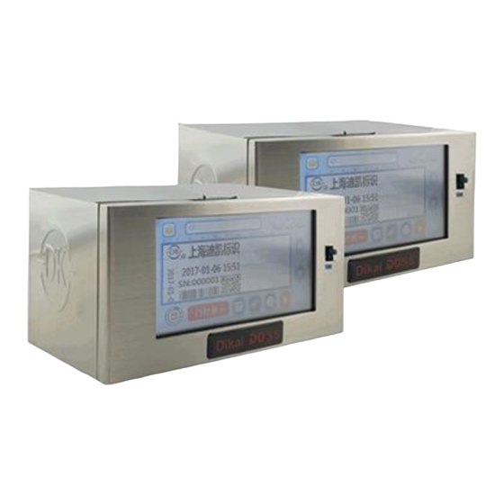
O P E R A T I O N A L M A N U A L D03S is available in two printer types, flexible for on-site installation: D03S Model: D03S Right Hand(D03S RH) D03S Left Hand(D03S LH) D03S can print lot number, date and time, variable data, etc directly onto kinds of packing film, variable data can be modified on controller. - Page 6 OPERATIONAL MANUAL 3. PRODUCT LABEL SN/ POWER/ RELATED DATA This label is located on the back panel of Control Box: Model Number Factory Location Serial Number Electricity Requirements DK logo Contact Information - 6 - D 0 3 S THERMAL TRANSFER OVERPRINTER...
-
Page 7: Parameter
O P E R A T I O N A L M A N U A L PARAMETER Print Head 32mm,300dpi; Print Area Intermittent:32mm X 60mm(W X L); Continuous: 32mm X 150mm(W X L); TTR Length Max 500m; 25mm 、33mm; TTR Width <... -
Page 8: Safety
The use of incompatible consumables can damage your printer. Use only consumables approved by DIKAI Company. Please be aware of the danger of power and rub-out signal which can run the printer. Please do move the printer with two hands to make sure not damage the printer. -
Page 9: Application And Abusing
O P E R A T I O N A L M A N U A L APPLICATION AND ABUSING The information for the safety, installation, operation, trouble shooting, schematics, parts illustrations and routine maintenance is listed throughout this manual. The following operation methods, but not limited to, are considered as abusing: ... -
Page 10: Installation
OPERATIONAL MANUAL 3. INSTALLATION COMPONENTS Diagraph 2 Components Packing List: 1、D03S Controller 8、Sample TTR 2、D03S Ribbon Cassette 9、Air Tube 3、D03S Printer 10、Drive Cable 4、Air Pressure Regulator 11、Power Cable (no plug) 5、Air Pressure Meter 12、I/O Cable 6、Relay 13、Power Cable 7、USB - 10 - D 0 3 S THERMAL TRANSFER OVERPRINTER... -
Page 11: Installation Requirements
3. Compressed air: max. 0.6Mpa, dry and uncontaminated air 4. Reliable printing signal——can be from relay, NPN/ PNP sensor, photo sensor or PLC 5. Enough space for installing printer 6. The installation should be done by DIKAI engineer or well trained operator STANDARD BRACKETS INTERMITTENT 1. - Page 12 4. Transition Roller Assembly Note: Standard bracket lengths are 350mm, 450mm, 500mm, 542mm, 600mm and 770mm. If standard bracket is not suitable for your packaging machine, do contact DIKAI for technical supports. - 12 - D 0 3 S THERMAL TRANSFER OVERPRINTER...
-
Page 13: Installation Of The Mounting Bracket
O P E R A T I O N A L M A N U A L INSTALLATION OF THE MOUNTING BRACKET Make sure enough room for the mounting bracket installation and easy operation; Make sure the bracket is well fixed and the printer roller and the packaging machine roller are parallel; ... - Page 14 OPERATIONAL MANUAL Continuous: Make sure the Print head is pointing to the center of the Rubber Roller. It can be set by parameter “Vertical” from the Controller. 1.5-2.5mm <120° The gap between Print head and Rubber Roller should be within 1.5~2.5mm, and the wrapping angle is no more than 120°.
-
Page 15: Installing The Controller
O P E R A T I O N A L M A N U A L INSTALLING THE CONTROLLER Diagraph 1 The bottom of Controller The control box is used for setting up the printer, it can access the maintenance and diagnostic function. 1. - Page 16 OPERATIONAL MANUAL IMPORTANT: Never connect or disconnect the cables to the D03S control box with the power on. Failure to do this may result in personal injury or machine damage. Communication Connector To connect with communication systems to get requested print information. External I/O Connector I/O connector is a D-type 9-pin connector to get external signal and output “WARNING”, “Error”...
-
Page 17: Printer Connectors
O P E R A T I O N A L M A N U A L 2-Drive Cable 6-SD Card 1-USB 5-I/O 4-Communication 3-Switch Diagraph 2 Connectors on Controller PRINTER CONNECTORS 3-Drive Cable 1-Encoder 2-Air Inlet Diagraph 5 Connectors on Printer Connectors on Printer Encoder Connector For continuous printers, an encoder is required to monitor the speed of the packaging film. - Page 18 OPERATIONAL MANUAL Out dia. 53.05mm tracking wheel Standard DK Encoder is a DB9 connector, can be insert to printer. Diagraph 3 Encoder Air Inlet: D03 requires the compressed air 0.25Mpa~0.45Mpa Set the air pressure by the followings: Mount the air pressure regulator: the IN connects 6mm air tube and the OUT connects 4mm air tube to join with the Air Inlet of printer.
- Page 19 O P E R A T I O N A L M A N U A L Press the Knob to lock the pressure regulator. Φ4mm air outlet Φ6mm air inlet Filter Diagraph 4 Air Pressure Regulator Drive Cable Connector A D-Type 44-pin connector, connect with the drive cable.
-
Page 20: Print Signal
OPERATIONAL MANUAL PRINT SIGNAL Print signals are provided by packing machine or extra sensor. When connect with packing machine, an extra relay is needed to avoid short circuit between packing machine & D03S.D03S prints once when the relay finish a closing course. If print signal is provided by extra sensor, D03S prints once when it changes from low to high voltage. - Page 21 O P E R A T I O N A L M A N U A L Controller PNP type PLC PRISIG+ black Print Signal PRISIG- blue PLC: 0V NPN type Sensor Wire Connection: NPN Sensor Controller Packing Brown Machine +24V PRISIG+ black Blue Packing...
- Page 22 OPERATIONAL MANUAL Controller Relay Packing Relay COM Machine +24V PRISIG+ black Relay NO Packing PRISIG- blue Machine 0V 2. Alarm Output I/O cable is a 9-pin cable, 4 & 7, 5 & 8 are normal open failure contact wires. PIN 4 PIN 5 PIN 7 PIN 8...
-
Page 23: Installation Dimension
O P E R A T I O N A L M A N U A L 3.10 INSTALLATION DIMENSION 3.10.1 LEFT HAND Best distance between print head and anvil rubber. - 23 - D 0 3 S THERMAL TRANSFER OVERPRINTER... - Page 24 OPERATIONAL MANUAL 3.10.2 RIGHT HAND Best distance between print head and rubber anvil - 24 - D 0 3 S THERMAL TRANSFER OVERPRINTER...
- Page 25 O P E R A T I O N A L M A N U A L 3.10.3 CONTROLLER DIMENSION - 25 - D 0 3 S THERMAL TRANSFER OVERPRINTER...
-
Page 26: Operation
OPERATIONAL MANUAL 4. OPERATION 4.1 START THE PRINTER 1 . Make sure all the air pipe, drive 2. Power on the printer, enter into the above cable, power cable, I/O cables are screen after a boot animation. Touch well connected, switch O to I to turn the machine on;... -
Page 27: Home Page
O P E R A T I O N A L M A N U A L HOME PAGE TEST Item Description Icon and Description The Current Print Job This option allows you to Files Management manage the various Database files. - Page 28 OPERATIONAL MANUAL Ready Cassette Open Initialization Running System Status Hardware Fault SD card loading problem Warning File Error System Time Abnormal This option allows you to access Menu the menu options This option allows access to the Quick Settings printer settings menus This option allows you to make Print Test a print test...
-
Page 29: Screen Icons
O P E R A T I O N A L M A N U A L SCREEN ICONS 4.3.1 MENU STRUCTURE - 29 - D 0 3 S THERMAL TRANSFER OVERPRINTER... - Page 30 OPERATIONAL MANUAL 4.3.2 MENU 4.3.3 QUICK SETUP Name Description Option Adjust the print in mm in the direction parallel Horizontal Unit 0.1mm to the print head Ribbon gap between two prints Unit 0.1mm Adjust the amount of energy being transferred Density 50-150,default is 100 into the print head...
- Page 31 O P E R A T I O N A L M A N U A L 4.3.4 ADVANCED SETTINGS Remark: Press enter with password (8888). - 31 - D 0 3 S THERMAL TRANSFER OVERPRINTER...
- Page 32 OPERATIONAL MANUAL 4.3.5 ADVANCED SETTINGS (USER PAGE) Remark: Click “ADVANCED SETTINGS” to enter with password 1111. Name Description Option PHD Resistance Set PHD resistance As per data on PHD Time of print head going down. Please adjust this value when Head Down Time Unit: ms prints show blurring or bur in the beginning of printing.
- Page 33 O P E R A T I O N A L M A N U A L Alarm output NO/ NC Alarm Alarm Switch Switch of alarm output ON/ OFF Additional Print Finish the print that is incomplete ON/ OFF Intermittent/ Choose print mode Machine Type...
- Page 34 OPERATIONAL MANUAL Deal with the received signals. “Normal”-Print once when get Model of printing Normal/ Equal a signal; “Equal Distance” – Automatically generate print signal Distance signal by setting in “Print at equal distance” R-type transverse Unit:0.1mm Horizontal distance between 2 R type prints offset distance Range:0-200 Printer automatically adjust print position according to the...
- Page 35 O P E R A T I O N A L M A N U A L FILE MANAGEMENT 4.3.6 Item Description Icon and Illustration Local Local Files USB Files Back Back to previous page MORE 4.3.7 - 35 - D 0 3 S THERMAL TRANSFER OVERPRINTER...
- Page 36 OPERATIONAL MANUAL Item Description Option Print Shifts or groups Add “User List” in print contents User List Set alarm output ON/ OFF Import “Shift code” that you edited in Can be at most 3 characters, can save Promark, print requested Shift Code 1500 records information in requested time period.
- Page 37 O P E R A T I O N A L M A N U A L DIAGNOSTICS 4.3.9 556 572 - 37 - D 0 3 S THERMAL TRANSFER OVERPRINTER...
- Page 38 OPERATIONAL MANUAL Name Description Option Print Signal Check print signal input YES/ NO Encoder Check encoder input YES/ NO Make print head move vertically, works in Valid data :0-600, click continuous mode only; this function only Head move provides preview, won’t change the vertical “OK”...
- Page 39 O P E R A T I O N A L M A N U A L SYSTEM INFORMATION 4.3.10 Name Description Option Status Machine status NORMAL/ ABNORMAL Print signal input YES/ NO Print Signal Ribbon Cassette Ribbon cassette well locked or not CLOSE/ OPEN Encoder Signal Encoder signal input...
- Page 40 OPERATIONAL MANUAL Ribbon (break) Check ribbon status NORMAL/ ABNORMAL Print (Miss) Print signal exists but miss prints NORMAL/ ABNORMAL Check encoder signal NORMAL/ ABNORMAL Encoder Motor Motor status NORMAL/ ABNORMAL Incomplete Incomplete prints NORMAL/ ABNORMAL - 40 - D 0 3 S THERMAL TRANSFER OVERPRINTER...
-
Page 41: Start/ Stop The Printer
O P E R A T I O N A L M A N U A L 4.4 START/ STOP THE PRINTER START THE PRINTER 4.4.1 SHANGHAI DK CODING SHANGHAI DK CODING IDLE STATUS RUNNING STATUS After initialization, the printer stops in IDLE status (IDLE), choose the print job (refer to 4.5).; Click , change to “RUNNING”... -
Page 42: File Management
.bmp, .dk, .ft and .xml. Build a folder named ‘dikai’ on the Sandisk USB provided by DIKAI, copy all 4 files to the ‘dikai’ folder. The print job saved in other folder cannot be read by the printer. - Page 43 O P E R A T I O N A L M A N U A L 4.5.2 IMPORT PRINT FILE 2. Click USB to import files into Local; 1. In IDLE status, click 3. File list appears in File Management 4.
- Page 44 OPERATIONAL MANUAL 4.5.3 CHOOSE PRINT FILE 2. Click “Local” to find files; 1. In home page, click 4. Click “Set as Working File”, “SUCCESS” 3. All imported files will appear, you can appears when it is set; search by file name; Shanghai DK Coding 操作成功!...
- Page 45 O P E R A T I O N A L M A N U A L 4.5.4 EXPORT PRINT FILE 1. Insert the USB containing the “dikai” 2. Click “Local”; folder; enter file management from home screen or menu screen in IDLE status.
-
Page 46: Parameter Setting
OPERATIONAL MANUAL 4.6 PARAMETER SETTING Set the Horizontal Offset 4.6.1 Shanghai Dikai Coding Industry 2. Click “Horizontal” option to pop up a 1. From the Home Screen (IDLE), click “Quick Set Up”. Digit Keypad. 4. Click”Back” and go back to Home 3. - Page 47 O P E R A T I O N A L M A N U A L Set the Vertical Offset 4.6.2 Shanghai Dikai Coding Industry 2. Click “Advance” to pop up a Digit Keypad. From the Home Screen (IDLE), click ”Menu”...
- Page 48 OPERATIONAL MANUAL Set the Print Delay 4.6.3 Shanghai Dikai Coding Industry 2. Click “Delay” to Digit Keypad. Click “Quick Set Up” from home screen. 5. The delay setting is done, click “back” to 3. Enter the number (intermittent: 1 means 1 MS;...
- Page 49 O P E R A T I O N A L M A N U A L The print position can be small-scale precisely adjusted by “Horizotal Offset “and “Vertical Offset”. (1=0.1mm) Note: In Continuous mode, Vertical Offset allows you to configure the position between print head and rubber roller.
- Page 50 OPERATIONAL MANUAL 4.6.6 Preview the Image Rotation 1. Click Quick Setup from home screen. 2. Click quick setup on the Home screen and click 180° ON OFF 4. The setting is done, click back to home screen. 3. There are ON/OFF options to choose, click ON. 5.
- Page 51 O P E R A T I O N A L M A N U A L 4.6.7 Set the darkness from user advanced settings screen 4.6.8 1. Click “Darkness” button from the 2. Enter the right value of darkness you Advanced Settings screen want and then click the “OK”...
- Page 52 OPERATIONAL MANUAL 4.6.8 Set the Left-hand/ Right-hand Shanghai Dikai Coding Industry 2. Click the portrait on Menu screen and you Click “MENU” from IDLE screen. can get a digit keyboard **** 3. Enter password of “8888” to Advanced 4. Go to page2 of advanced settings screen.
- Page 53 3. There are continuous and intermittent options to choose. screen. 4.6.10 Set the System Time (Real Time Clock) 4.6.11 Shanghai Dikai Coding Industry 1. Enter into Advanced Settings from home 2. Click System Time to pop up the digital screen. keyboard 3.
- Page 54 4. The setting is done, click back to home screen. Note: cannot enter into advanced setting and system diagnostic screen when the printer is running. Currently Dikai D03s only supports two languages of Chinese& English - 54 - D 0 3 S THERMAL TRANSFER OVERPRINTER...
- Page 55 O P E R A T I O N A L M A N U A L 4.6.12 Choose the type of Printhead 3. Press the “Type of Printhead” in Page 3 1. Enter the “Advanced Settings” when machine is in IDLE.
- Page 56 4, Return to “Advanced settings” after above the ribbon choosing page steps. Ps: D03S machine only supports the ribbon types showing in the page. Dikai will not guarantee the well-running of machines and ribbons if you use other types of ribbons. - 56 -...
- Page 57 O P E R A T I O N A L M A N U A L 4.6.14 Edit of Custom Texts 2014-09-10 14:30 SN:000001 0001 1. Click the file name to enter Edit screen from 2. Click the text you need Home screen.
- Page 58 OPERATIONAL MANUAL 4.6.15 Set the Shift No. 2014-09-10 14:30 SN:000001 0001 SHIFT:A01 2. Click MORE from Menu screen. 1. Enter into Menu screen in IDLE status. 4. Select requested shift No. from User list 3. Click User list. screen (at most 32 shifts). 2014-09-10 14:30 SN:000001 0001 SHIFT:A02...
- Page 59 O P E R A T I O N A L M A N U A L 4.6.16 4.6.17 2014-09-10 14:30 SN:000001 0001 Shift:A02 IDLE 1. Click Menu on IDLE screen 2. Click More 4. Please choose ON or OFF as needed. 3.
- Page 60 OPERATIONAL MANUAL 4.6.17 Change the password 2014-09-10 14:30 SN:000001 0001 Shift:A02 IDLE 1、在待机 2. Click More 1.Click Menu on IDLE screen Click Manu 4. Input the current password on the password 3. Click Password management screen and click OK. The default password is “1111”...
- Page 61 O P E R A T I O N A L M A N U A L Shift code 4.6.18 SN:000001 0001 IDLE Save the SHIFTCODE file to DKUPDATE 2. Click More folder in the USB, click Menu on IDLE screen 4.
- Page 62 OPERATIONAL MANUAL System calibration 4.6.19 The machine should be system calibrated after any change of the followings: Change printer unit Change main board Change controller box Change interface board Change DB44 connection Change driving motors Update the software in PCB 1, Take off the ribbon cassette when the machine is on 3.
-
Page 63: Upgrading The Controller Box
Note: there are two types of program (ARM & MCU) need to be upgraded at the same time. At most 6 files can be shown on one screen. And please save the files into “dikai” folder, otherwise the printer cannot read them... - Page 64 OPERATIONAL MANUAL 4.7.2 Interface upgrading 2, Copy the folder named ”DWIN_SET” into the 1, Use a SD card (Recommend Sandisk), and format it with “FAT32”and “4096”like in the root directory of SD card. picture. 4, The control box will do the upgrading 3, Turn on the control box on and insert the SD automatically.
-
Page 65: Removing The Cassette
Op era tion Manual 4.8 REMOVING THE CASSETTE 1. Stop the printer into ready screen (IDLE) 2. Unlock the cassette lever 3. Withdraw the cassette with the handle Note: Follow the opposite steps to install the cassette 4.9 LOADING OR REPLACING THE RIBBON 4.9.1 The Cassette Structure Used... - Page 66 OPERATIONAL MANUAL 4.9.2 Loading or Replacing TTR (Left-hand Machine) 3. Lock the Reel on the elastic 1. Remove the cassette. 2. Put the cassette evenly on the lever. worktable. 4. Rotate the locking sleeve as 6. Take out the used TTR as 5.
- Page 67 Op era tion Manual 4.9.3 Loading or Replacing TTR (Right-hand Machine) 3. Lock the Reel on the elastic 1. Remove the cassette. 2. Put the cassette evenly on the lever. worktable. 4. Rotate the locking sleeve as 6. Take out the used TTR as 5.
- Page 68 OPERATIONAL MANUAL 4.9.4 Re-connecting a Broken Ribbon Broken 1. Remove the cassette. 2. Wind the remaining waste ribbon onto the waste core. 3. Pull unused ribbon from the 4. Rewind the ribbon and keep t h e joint ribbon supply and w i n d it onto between the two as flat as possible.
-
Page 69: Test The Current Print Job
Op era tion Manual 4.10 TEST THE CURRENT PRINT JOB TEST SHANGHAI DIKAI We need to test the print result after installation. Turn on the printer, wait to enter the Ready screen. Select print job (Refer to 4.7). -
Page 70: Maintenance
Please use printing head cleaning wipe provided by DIKAI or a soft cloth in Isopropanol (Refers to the below image). Better clean the print head once a day if the printer keeps running. -
Page 71: Maintenance Scheme
Check condition of Platen rubber. Clean or replace it if necessary. The platen rubber needs to be smooth, flat and free from debris. To change the platen rubber, first take the old platen rubber off. The entire adhesive should be removed from the metal platen base. Replace with a DIKAI platen rubber for best results. - Page 72 OPERATIONAL MANUAL 5.2.2 Monthly Checks Check the mounting bracket: Check if the mounting bracket is firm, make sure each screws is fixed. Check cable connection: you must have proper tools to install DB44 cables, make sure the cable is securely connected before supplying power to the equipment.
- Page 73 Op era tion Manual D 0 3 S Thermal Transfer Overprinter - 73 -...
-
Page 74: Replacing The Printhead
OPERATIONAL MANUAL 5.3 REPLACING THE PRINTHEAD 1. Turn off the power to the controller and cut off the air supply to the printer body. 2. Remove the ribbon cassette. 4. Take out the Printhead as shown. 3. Insert ∅ 2mm screwdriver to the hole. 5. -
Page 75: Replacing The Reel Roller
Op era tion Manual Each print head has a individual resistance level, and the voltage level setting required for each is different. A label on the print head displays the rating for that particular one. In this case, R=1267 This value must be entered into the controller menu structure, or will be taken as an abuse. -
Page 76: Trouble Shooting
OPERATIONAL MANUAL 6. TROUBLE SHOOTING The Diagnostics is displayed in abbreviated form on the Home screen, gives an aid to troubleshooting. The icons informing you of problems or potential problems include the followings. Icon Diagnose Cause Solution Turn off power, remove ribbon cassette, check items as The printhead is not below. - Page 77 Check if there are too many merge variable data, if on the screen yes, cancel merge. Print job download from USB is not fully Use DIKAI U-disk.. shown Re-load print job. Check if print job is selected correctly. Make sure proper space between printhead and rubber anvil or roller.
-
Page 78: Schematics And Parts Illustrations
OPERATIONAL MANUAL 7. SCHEMATICS AND PARTS ILLUSTRATIONS 7.1 CONTROLLER BOX Item No Description Part No. Quantity D03S Controller Box C03S03000 Metal Shell C03S03027X Main Control Board C03S03008 Power Supply Unit C03S03026 Touch Screen C03S03032 Power Socket (With Switch) C03S03025 - 78 - D 0 3 S THERMAL TRANSFER OVERPRINTER... -
Page 79: Cassette Assembly
Op era tion Manual 7.2 CASSETTE ASSEMBLY Item No. Description Part No. Quantity Cassette Assembly (LH) C03S01000LH Cassette Assembly (RH) C03S01000RH Cassette Locating Pin C03S01007 Supply Reel Assembly C03S01012 Elastic Support Shaft Y0101029 Elastic Cam Y0301028 Friction Elastic Lever Y0101027 Hall Roller Assembly C0301024L Take-up Reel Assembly... - Page 80 OPERATIONAL MANUAL Item No. Description Part No. Quantity Supply Reel Assembly C03S01012 Transmission Sleeve Y0101021 Compression Spring Y0101031 Locking Clip Y0301016 Locking Sleeve Y0101015 O-Ring Y0101035 Reel Base Y03S01014 Tighten Shaft Y0101006 Supply Reel Y0101013HA - 80 - D 0 3 S THERMAL TRANSFER OVERPRINTER...
- Page 81 Op era tion Manual Item No. Description Part No. Quantity Take-up Reel Assembly C03S01019 Transmission Sleeve Y0101021 Compression Spring Y0101031 Locking Clip Y0301016 Locking Sleeve Y0101015 O-Ring Y0101035 Reel Base Y03s01020 Tensioner Shaft Y0101006 Take-up Reel Y0101013HA D 0 3 S Thermal Transfer Overprinter - 81 -...
-
Page 82: Printer Unit
OPERATIONAL MANUAL 7.3 PRINTER UNIT 7.3.1 General Parts Item Description Part No. Quantity Peel Roller Assembly C0302013 Peel Fix Cap Y0102062 Peel Roller C0102014 Peel Roller Shaft Y0302015 Peel Roller Support Y0302016 Item No. Description Part No. Quantity PHM Mounting Assembly C0102003 PHM Mounting Shaft Y0102005... - Page 83 Op era tion Manual Item Description Part No. Quantity Printhead Module Assembly C0102006 Printhead C0102008 32 Cable Protector Y0302094 Item Description Part No. Quantity Support Plate Y0302074 Assembly Cable Guide Block Y0302061 Printhead Cable Y0102058 Support Plate Y0302022 Support Pad Y0302057 D 0 3 S Thermal Transfer Overprinter - 83 -...
- Page 84 OPERATIONAL MANUAL Item Description Part No. Quantity Carriage Cylinder Assembly C0102010 Reset Pull Spring Y9900308 Cylinder C0102076 Printhead Pull Spring Y9900298 Item Description Part No. Quantity Shaft Mounting Block C0302051 Shaft Y0102017 Mounting Block Y0302018 - 84 - D 0 3 S THERMAL TRANSFER OVERPRINTER...
- Page 85 Op era tion Manual Printer Unit 7.3.2 Item No. Description Part No. Quantity Printer Unit ---Left hand C03S02000LH Printer Unit ---Right hand C03S02000RH Left Front Cover Y0302043 Hall Element C9900326 Mounting Block Assembly C0102023X Transmission Shaft Y0302026 Driving Capstan Y0102025 Printhead Cable Fixer Y0302048 Support Assembly...
- Page 86 OPERATIONAL MANUAL Item No. Description Part No. Quantity Basic Plate Y03S02001 Locking Block Y0102028 Hall Mounting Block Y0302075 Locking Sleeve Y0102027 Hall Element C9900326 Connector Y9900303 Connector Fix Block Y0102050 Solenoid Valve C9900290S Solenoid Valve Fix Block Y0302032 Motor Y0302001 Motor Y0102052Z Interface PC Board...
-
Page 87: Other Spares
Op era tion Manual 7.4 OTHER SPARES Item No. Description Part No. Specifications Quantity Power Cable (with plug) Y0105022 Power Cable (no plug) Y0105002 Drive Cable Y0105003 I/O Cable Y0105004 TTO Ribbon Sample DG33100BK 33mm*100m Fastening Accessories Y0105008 Air Pipe Assembly C0105009 C0105010G Air Pressure Regulator... -
Page 88: Recommended Spares
OPERATIONAL MANUAL 7.5 RECOMMENDED SPARES Item Description Part No. Quantity Peel Roll C0102014 Hall Roll Assembly C03S01024 Belt Y9900323 Friction Elastic Lever Y0101027 Tighten Shaft Y0101006 Locking Clip Y0301016 Hall Element C9900326 Print Head Cable Y0102058 - 88 - D 0 3 S THERMAL TRANSFER OVERPRINTER... -
Page 89: Consumables Introduction
Op era tion Manual 8. CONSUMABLES INTRODUCTION DIKAI TTR DG, Wax/Resin TTR; DC, Premium Wax/Resin TTR; DB, Ultrathin Wax/Resin TTR; DT, Resin TTR Wax/Resin TTR Combination with wax and resin, with advantages of two material. - Page 90 OPERATIONAL MANUAL - 90 - D 0 3 S THERMAL TRANSFER OVERPRINTER...
Need help?
Do you have a question about the DK-D03S and is the answer not in the manual?
Questions and answers
Good morning. I have 1 unit new of Dikai D03S in my factory but I have problem with the the include flashdisk, so that's why I could'nt operate my Dikai print to create new file. I need to sent softfile for operate my printer Dikai,please.