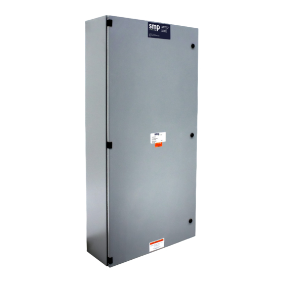
Summary of Contents for RVE SMP-12
- Page 1 Installation Manual GENERATION 1.5 SMP-12 SMP-15 SMP-18 SMP-21 rve.ca 3480 boul. Industriel support@rve.ca Laval (Québec) H7L 4R9 RECHARGE VÉHICULE ÉLECTRIQUE...
-
Page 2: Table Of Contents
RVE by email at support@rve.ca as soon as possible. INSTALLATION EXAMPLES INSTALLATION DISCLAIMER RVE does not accept any responsibility and will not be liable for any loss, damage or expense of any kind whatsoever and howsoever caused by improper installation of its products, WARNING... -
Page 3: Introduction
INTRODUCTION tional power limits. The SMP consists of a meter module, The Smart Metering Panel, hereafter referred to as SMP, ma- relay controller and relay panel (see image below). The typical nages Electric Vehicle Supply Equipment (EVSE) power flow system has one 3Φ main meter and up to twenty-one (21) 2Φ to optimize existing electrical assets and maintains opera- meters with 2Φ... -
Page 4: Diagram Of Panel Enclosure
DIAGRAM OF PANEL ENCLOSURE IMAGE 2. SMP-15 BOTTOM GROUDING RELAYS RELAYS LUGS SMP-15 EXITS ENTRANCES GROUNDING EV ENTRANCES TERMINAL BLOCK FOR RELAYS 01 TO 15 SM45-31 POWER POWER SUPPLY SUPPLY GROUNDING CT43, L1 CT43, L1 CT44, L2 CT44, L2 CT45, L3 GROUDING CT45, L3 LUGS... -
Page 5: Dimensions
DIMENSIONS IMAGE 3. DIMENSIONS OF THE SMP GENERATION 1.5 24 " 8 " 48 " 24 " 8 " RECHARGE VÉHICULE ÉLECTRIQUE... -
Page 6: Description
DESCRIPTION STEP 2 2.1 Turn the mounting brackets 90° (vertically) ; The SMP is an integrated switching control and measuring Before After system with current transformers for the submetering modules (or branch modules), magnetic latching power relays of up to 240/60A and current transformers for mete- ring the main power supply of the distribution panel (distri- bution panel not included). - Page 7 5.3 Connect the distribution panel according to the order of NOTE the phase indicated on the terminal blocks in the SMP ; It is important to note that these are 0-400A* solid core current transformers. They cannot be installed without disconnecting the main electrical conductors from the distribution panel.
- Page 8 The maximum amperage set point is configured at the factory according to the information you provided when placing the order. RVE’s technical support team can validate and modify this threshold remotely; please email support@rve.ca if needed. RECHARGE VÉHICULE ÉLECTRIQUE...
-
Page 9: Installation Examples
INSTALLATION EXAMPLES SMP-15 with Panel MAIN PANEL Electricity meter Transformer 3 phases 208/120V EV Charger(s) 200A up to 21, depending on the model) 125A ELECTRICAL CHARGING INFRASTRUCTURE INFRASTRUCTURE Panel Electricity Transformer meter 3 phases 208/120V EV Charger(s) up to 21 depending on the model) ELECTRICAL CHARGING... - Page 10 Panel Transformer Electricity meter 3 phases 208/120V EV Charger(s) (up to 21, depending on the model) CHARGING ELECTRICAL INFRASTRUCTURE INFRASTRUCTURE Panel EV Charger(s) (up to 21, depending on the model) Panel Electricity Transformer meter 3 phases 208/120V EV Charger(s) (up to 21, depending on the model) ELECTRICAL CHARGING...
- Page 11 TECHNICAL SUPPORT To report any problems, please contact RVE by email at support@rve.ca.

Need help?
Do you have a question about the SMP-12 and is the answer not in the manual?
Questions and answers