Advertisement
CAUTION-Never have more
than one person on the
ladder at a time. Maximum
weight capacity on ladder is
300 pounds.
Maximum Weight Capacity (User and
Equipment) - 500 pounds (226 kg)
Every year people are injured from hunting related falls. Most of these injuries could have been prevented by
following the instructions and warnings provided with the tree stand and safety harness. Tree stands are
used at height and falls can result in serious injury or death. Your own safety, and the safety of any user of
this product, should be your first priority. In order to reduce your risk of injury, you MUST read and
thoroughly understand all of the safety warnings, usage instructions and other information contained within
the written and safety video instructions and warnings provided with this product, and any other hunting
equipment used. Retain the instructional and warning materials and review them periodically (at least once a
year and always with any new user). Failure to follow all instructions and warnings may lead to serious injury
or death. DO NOT USE THIS PRODUCT UNTIL AND UNLESS YOU HAVE READ AND THOROUGHLY
UNDERSTAND ALL INSTRUCTIONS, SAFETY WARNINGS AND OTHER MATERIALS. If you have any
questions, do not use the product until you have contacted the manufacturer at 949-262-3416 or email
customerservice@innopower.biz.
Monday through Friday, 8:00 am to 5:00 pm ET. If you are unable to speak with a
representative, please leave a voicemail with your contact information and your
For Customer Service, please call 949-262-3416 or
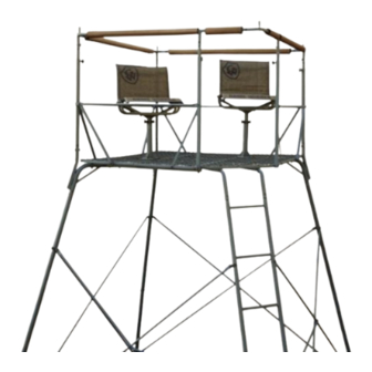
Instruction Manual
QUAD POD DS
ITEM:175260
Business Hours:
call will be returned within one (1) business day.
E-mail: customerservice@innopower.biz
(Made In China)
1
Advertisement
Table of Contents

Summary of Contents for TMA GAME WINNER QUAD POD DS
- Page 1 Instruction Manual QUAD POD DS CAUTION-Never have more ITEM:175260 than one person on the ladder at a time. Maximum weight capacity on ladder is 300 pounds. Maximum Weight Capacity (User and Equipment) - 500 pounds (226 kg) Every year people are injured from hunting related falls. Most of these injuries could have been prevented by following the instructions and warnings provided with the tree stand and safety harness.
-
Page 2: Table Of Contents
Table of Contents Page Warnings ……………………………………………………………………… 3-6 Parts List ……………………………………………………………………… 7-11 Tools Required ........………………………………………… 11 Hardware ……………………………………………………………………… 12-16 Product Diagram ……………………………………………………………… 17 Assembly Instructions ……………………………………………………….. 18-36 Installation Instructions ……………………………………………………… 37-38 Care and Maintenance ………………………………………………………. 39 Warranty Information ………………………………………………………… 40 Note: Before beginning assembly of product, make sure all parts are present. -
Page 3: Warnings
Warnings ATTENTION! WHEN YOU SEE A SYMBOL OR THE WORD “WARNING!” BE SURE TO READ THE MESSAGE! THE INFORMATION CONTAINED IN THESE MESSAGES CAN SAVE YOUR LIFE OR PREVENT SERIOUS INJURY!! BE SAFE! FOLLOW ALL WARNINGS!! WARNING! FALLS FROM A POD STAND CAN OCCUR ANYTIME AFTER LEAVING THE GROUND.THESE FALLS RESULT IN EITHER SERIOUS INJURY OR DEATH! FOR YOUR PERSONAL SAFETY, PLEASE TAKE A MOMENT TO CAREFULLY READ THIS PRODUCT INSTRUCTION MANUAL IN ITS ENTIRETY BEFORE ATTEMPTING TO ASSEMBLE, SET-UP, INSTALL AND/OR OTHERWISE USE... - Page 4 Warnings WARNING! Replace all hardware/cables/nuts/bolts/clips on your pod stand if inspection reveals any damage, including but not limited to wear, rot, corrosion, cracks, fraying, deterioration and/or any other type of damage. Use only Game Winner replacement parts. The product is tested to be used only with genuine Game Winner parts.
- Page 5 Warnings WARNING! DO NOT modify, fix/repair, alter, bend, cut, weld, or heat this product in any way. Failure to follow these instructions may result in serious injury or death! WARNING! DO NOT lean out from a pod stand for any reason. Failure to follow these instructions may result in serious injury or death! WARNING! Never jump from or bounce on a pod stand for any reason.
- Page 6 Warnings WARNING! When using a pod or tower stand the risk of a fall can occur anytime after leaving the ground. Falling from a pod or tower stand can result in serious injury or death. WARNING! A fall arrest system/full body harness (FAS/FBH) that meets industry standards for treestands is not included with pods and tower stands.
-
Page 7: Parts List
Parts List Back Platform Middle Platform Front Platform Platform Support Bar(L=772MM) Bent Ladder Support Bent Leg Support Lower Seat Post... - Page 8 Parts List Square Plate Front Rail Support( with threaded knobs hole ) Back Rail Support(w/tab) Reinforce Bars for Rail- Short(L=1000 Diagonal Brace(L=543. 6MM) Inclined Support Bar Reinforce Bars for Rail- Long (L=1406MM) Shooting Rail#1 Shooting Rail#2...
- Page 9 Parts List 17 Shooting Rail Connection#1 18 Shooting Rail Connection#2 19 Shooting Rail Support Bars 20 Upper Leg Sections 21 Upper Ladder Section 22 Lower Leg Sections 23 Lower Ladder Section 24 #1 Female Cross Brace (L=1061.5MM)
- Page 10 Parts List #1 Male Cross Braces (L=1493.5MM) #2 Female Cross Brace (L=958MM) #2 Male Cross Braces (L=1412MM) Short support Braces (L=894MM) 29 Seat Base Frame 30 Seat & Backrest Frame 31 Spreader Handle 32 Spreader Adjuster Tube...
-
Page 11: Tools Required
Parts List 33 Upper Seat Post 34 Leg Bracket 35 Ladder Bracket 36 Ground Stake Tools Required (Provided) Wrench (2 pcs) -
Page 12: Hardware
Hardware Step M8X55 (with 2 steel washers and 1 locknut) Step M8X55 (with 2 steel washers and 1 locknut) Step M8X55 (with 2 steel washers and 1 locknut) Step M8X60 (with 2 steel washers and 1 locknut) Step M8X60 (with 2 steel washers and 1 locknut) Step... - Page 13 Hardware Step M8X60 (with 2 steel washers and 1 locknut) Step M8X40 (with 2 steel washers and 1 locknut) Step M6X35 (with 2 steel washers and 1 locknut) Step M6X40 (with 2 steel washers and 1 locknut) Step M6X50 (with 2 steel washers and 1 locknut) Step...
- Page 14 Hardware Step M6X30 (with 1 steel washer and 1 wingnut) Step M6X30 (with 1 steel washer and 1 wingnut) Step M8X25 Threaded Knob Step M6X50 (with 2 steel washers and 1 locknut) Step M6X35 (with 2 steel washers and 1 locknut) Step M6X55 (with 2 steel washers...
- Page 15 Hardware Step M6X40 (with 2 steel washers and 1 locknut) Step M6X55 (with 2 steel washers and 1 locknut) Step M6X40 (with 2 steel washers and 1 locknut) Step M6X16 (with 2 steel washers and 1 locknut) Step M6X45 (with 2 steel washers and 1 locknut) Step...
- Page 16 Hardware Step M6X16 (with 2 steel washers and 1 locknut) Step M8X55 (with 2 steel washers and 1 locknut) Step M6X35 (with 2 steel washers and 1 locknut) Step M6X16 (with 1 steel washer) Step M6X35 (with 2 steel washers and 1 locknut) Step M8X40 (with 2...
-
Page 17: Product Diagram
Product Diagram Product Identification Mark for Customer Service (on #9 part) -
Page 18: Assembly Instructions
Assembly Instructions Step 1: Locate the Back Platform (#1) and Middle Platform (#2). Assemble platforms together using six (6) M8x55 Bolts, twelve (12) Steel Washers and six (6) Locknuts as shown in Figure1. IMPORTANT NOTE – DO NOT TIGHTEN BOLTS. Figure 1 Connect Back and Middle Platforms Step 2:... - Page 19 Assembly Instructions Step 3: Locate two Platform Support Bars (#4). Install the Platform Support Bars (#4) onto the assembled Platform using four (4) M8x55 Bolts, eight (8) Steel Washers and four (4) Locknuts as shown in Figure 3. IMPORTANT NOTE – DO NOT TIGHTEN BOLTS.
- Page 20 Assembly Instructions Step 5: Locate two Bent Ladder Supports (#5). Install the Bent Ladder Supports (#5) onto the assembled Platform using two (2) M8x60 Bolts, four (4) Steel Washers and two (2) Locknuts as shown in Figure 5. Tighten all bolts from step 1 through 5.
- Page 21 Assembly Instructions Step 7: Locate two Lower Seat Posts(#7) and Square Plates(#8). Note: Seats can be installed in multiple configurations on platform (see Figure 7 with light and dark seat posts showing seat locations). If you install seat post in center location on platform, only one seat can be installed.
- Page 22 Assembly Instructions Step 9: Locate three Back Rail Supports (#10). Install each Back Rail Support (#10) onto the Bent Leg Support (#6) using three (3) M6x40 Bolts, six (6) Steel Washers and three (3) Locknuts as shown in Figure 9. Important Note: Position Front Rail Supports so threaded knob holes are facing toward the...
- Page 23 Assembly Instructions Step 11: Locate two Diagonal Braces Step11A (#12) and two Inclined Support Bar(#13). Step 11A: Install the Diagonal(#12) onto the assembled platform using two (2) M6x50 Bolts, four (4) Steel Washers and two (2) Locknuts as shown in Figure 11. Step 11B: Install the Inclined Support Bar(#13) onto the assembled platform using two...
- Page 24 Assembly Instructions Step 13: Locate four Diagonal Braces (#12). Install the Diagonal Brace(#12) onto the assembled platform using four (4) M6x50 Bolts, eight (8) Steel Washers and four (4) Locknuts as shown in Figure 13. Figure 13 Install Diagonal Brace Step 14: Locate Shooting Rail(#15 and #16) and Shooting Rail...
- Page 25 Assembly Instructions Step 15: Locate five Shooting Rail Support Bars(#19). Install the five Shooting Rail Support Bars(#19) onto the assembled Shooting Rail using five (5) M6x30 Carriage Bolts, five (5) Steel Washers and five (5) Wing Nut as shown in Figure Figure 15 Install Shooting Rail Support Bar Step 16:...
-
Page 26: Installation Instructions
Installation Instructions Step 17: WARNING: Remaining Assembly Steps require a minimum of four (4) adults to complete assembly. Failure to follow these instructions may result in serious injury or death! Locate three Upper Leg Sections (#20). Install the three Upper Leg Section (#20) onto the Bent Leg Supports (#6) using three (3) M6x50 Bolts, six (6) Steel... - Page 27 Installation Instructions Step 19: Locate three Leg Brackets (#34). Install the three Leg Brackets (#34) onto the Upper Leg Section (#20) using three (3) M6x55 Bolts, six (6) Steel Washers and three (3) Locknuts as shown in Figure Figure 19 Install Leg Bracket Step 20: Locate two Ladder Brackets...
- Page 28 Installation Instructions Step 21: Locate three Lower Leg Sections (#22). Install the three Lower Leg Sections (#22) onto the Upper Leg Section (#20) using three (3) M6x50 Bolts, six (6) Steel Washers and three (3) Locknuts as shown in Figure 21. Figure 21 Install Lower Leg Section Step 22:...
- Page 29 Installation Instructions Step 23: Locate three Leg Brackets (#34). Install the three Leg Brackets (#34) onto the Lower Leg Section (#22) using three (3) M6x55 Bolts, six (6) Steel Washers and three (3) Locknuts as shown in Figure Figure 23 Install Leg Bracket Step 24: Locate two Ladder Brackets...
- Page 30 Installation Instructions Step 25: Locate four #1 Female Cross Braces(#24). Install #1 Female Cross Brace (#24) onto the Leg Bracket(#34) using four (4) M6x16 Bolts, eight (8) Steel Washers and four (4) Locknuts as shown in Figure Figure 25 Install #1 Female Cross Brace Step 26: Locate four #1 Male Cross Braces(#25).
- Page 31 Installation Instructions Step 27: Install the Assembled Cross Brace to the Leg Bracket (#34) using four (4) M6x16 Bolts, eight (8) Steel Washers and four (4) Locknuts as shown in Figure 27. Figure 27 Install Cross Brace Step 28: Locate four #2 Female Cross Braces(#26).
- Page 32 Installation Instructions Step 29: Locate #2 Male Cross Brace(#27) and two (2) Short support Braces(#28) Install #2 Male Cross Brace (#27) into #2 the Female Cross Brace(#26). Assemble the two Cross Braces and Short support Brace(#28) using one (1) M6x45 Bolt, two (2) Steel Washers and one (1) Locknuts as shown in Figure Repeat for other cross braces...
- Page 33 Installation Instructions Step 31: Locate five (5) Ground Stakes(#36). Secure the Ladder and Legs to the ground using five (5) Ground Stakes(#36) as shown in Figure 31. Figure 31 Secure Quad Pod Using Ground Stake Step 32: Locate two (2) Seat Base Frames(#29) and two (2) Seat &...
- Page 34 Installation Instructions Step 33: Locate two (2) Seat Spreader Tools (#31 and #32). Step 33A: Assemble each Spreader Handle (#31) and Step 33B Spreader Adjuster Tube(#32) using one(1) M6x35 Bolt, two (2) Steel Washers and one (1) Locknuts as shown in Figure Step 33B: Install one (1) Seat Spreader Tool onto Seat &...
- Page 35 Installation Instructions Step 35: Locate two (2) Upper Seat Posts (#33). Install one (1) Upper Seat Post(#32) onto seat frame using four (4) M8x40 Bolts, eight (8) Steel Washers and four (4) Locknuts as shown in Figure 35. Repeat for second seat. Figure 35 Install Upper Seat Post Step 36:...
- Page 36 Installation Instructions Step 37: Tie a hoist rope (not included) to the seat. Climb onto the platform and using hoist rope lift seat with the help of other adults. Install the assembled seat onto the Lower Seat Post (#7) as shown in Figure 37. Repeat this step for the second seat.
- Page 37 This rugged- construction makes your Game Winner Quad Pod DS physically heavy. As such, you should never attempt to install this pod stand by yourself. YOU MUST HAVE A MINIMUM OF FOUR (4) ADULTS FOR THE SAFE ERECTION OF YOUR POD STAND.
- Page 38 STEP1:After making sure that the ground is level and with the assistance of three (3) other adults (for a total of four (4) adults) gently raise your Game Winner Quad Pod DS into a standing position. Once standing, make certain the seating platform is level and the pod stand is installed on solid, level ground. If the seat or...
-
Page 39: Care And Maintenance
Care and Maintenance WARNING! Proper maintenance and inspection is required for this product. Thoroughly inspect this or any other Game Winner product(s) prior to use for signs of wear, rot, corrosion, cracks, fraying, deterioration and/or any other type of damage. DO NOT use this or any other Game Winner product(s) if they show evidence of wear, rot, corrosion, cracks, fraying, deterioration and/or any other type of damage. -
Page 40: Warranty Information
Warranty Information Important Warranty Information Important Warranty Information Innopower Inc. warrants this Game Winner product against defect(s) in material and workmanship, under proper use and storage, for the period of one (1) year from the date of purchase. Proof of purchase, plus, the return of your warranty application card to our home office, is required for any warranty claim.
Need help?
Do you have a question about the GAME WINNER QUAD POD DS and is the answer not in the manual?
Questions and answers