
Summary of Contents for CDS CDS-ECW Series
- Page 1 (QP0907-2) DC Servo Motor Driver Purchase Guide Operation Manual CDS-ECW Series...
-
Page 2: Table Of Contents
DC BRUSHED SERVO MOTOR DRIVER CDS-ECW SERIES Table of Contents (1) Installation........................P1 (2) Specifications...................... P2~P3 (3) Layout of PC Board Components................P4 (4) Block diagram......................P5 (5) Instruction of Power Supply..................P6 (6) Selection and Match of Specification for Speed Feedback Voltage....P7 (7) Instruction of Signals/Wiring................ -
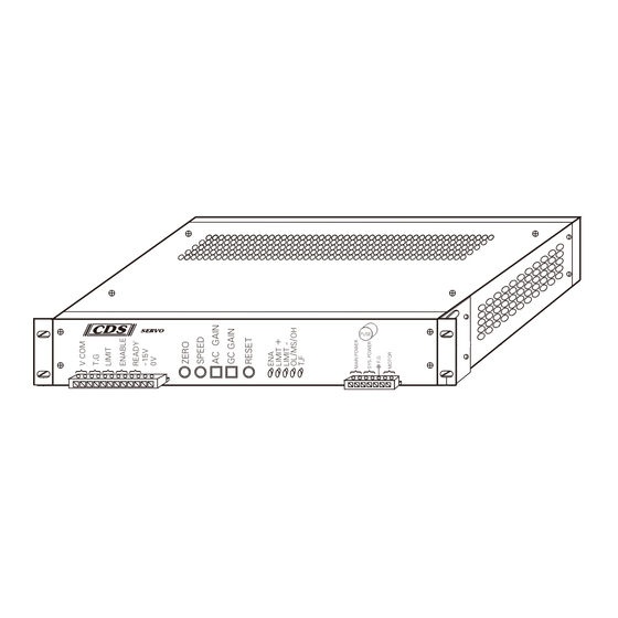
Page 3: Installation
INSTALLATION ECW Series 227mm 58mm 151mm FUSE 31mm 52.5mm 246mm 257mm Notices for installation environment: (1) The ambient temterature shall not exceed the limit of 0~50℃. (2) The relative humidity shall not exceed the limit of 10~90%RH (not dew). (3) Environment with corrosive and inflammable gases shall be avoided. (4) Environment with dust, salt ,and ferrousdust shall be avoided. -
Page 4: Specifications
Abnormal Feedback. Continuous Voltage Continuous Current Series Title Example : CDS - 05 10 F EL Specifications of this driver : Continuous Current:5A (Peak Current:13A) Continupus Voltage:100VDC (Maximum Voltage 113VDC) Trip-off Protection at Abnormal Feedback EL : L board without case... - Page 5 NOTE OF SPECIFICATIONS ●Type of Control : PWM effective switching frequency of: CDS-0510E & CDS-0515E 20KHZ 20KHZ CDS-0710E & CDS-0715E 16KHZ CDS-1010E & CDS-1015E CDS-1510E 16KHZ ●Entry of Speed Command : DC±10V /Rated Speed. ●Voltage Feedback Gradient DC : 7V/1000 rpm 9.5V/1000 rpm...
- Page 6 2003/8/25 R139 R113 R153 RP145 RP144 2W1E RP67 R151 104/630 RP66 R201 R129 R127 R128 RP60 R152 R147 RP65 R134 R132 R111 R133 R204 R203 TF OFF R205 R100 R206 R143 SC19 R141 R142 R104 R112 R200 R101 R105 R202 SC17 FUSE2 BRIDGE2...
-
Page 7: Block Diagram
Block diagram... -
Page 8: Instruction Of Power Supply
INSTRUCTION OF POWER SUPPLY Supplying AC power to CDS-E Series shall be fine since the Series is equipped with built-in rectifying system. On the panel board of driver U1V1 is the main power, U2V2 is power supply terminal of control system. - Page 9 SELECTION AND MATCH OF SPEED FEEDBACK VOLTAGE (While it is ready to leave the factory, otherwise, T/G gradient will be set at 7V/1000rpm) TACHOGENERATOR (T.G.) can be adopted for the speed feedback of CDS-E Series. Analog voltage input (F/V) converted from Frequency can also be used.
- Page 10 SIGNAL DESCRIPTION DIAGRAM (CDS-E) CDS-E SERVO DRIVER SIGNAL DESCRIPTION +/- 10V V COM. INPUT COM. 0V T.G FEEDBACK T.G 0V + LIMIT + LIMIT SW. - LIMIT - LIMIT SW. OUTPUT +15V COMMON ENA INPUT SERVO READY (MAX. DC24V,60mA) OUTPUT -15V OUTPUT -15V (LOAD CURRENT 20mA MAX.)
- Page 11 DESCRIPTION DIAGRAM OF VR SPEED ADJUSTMENT WIRING (CDS-E) CDS-E SERVO DRIVER V SERIES SIGNAL DESCRIPTION +/- 10V V COM. INPUT COM. 0V T.G FEEDBACK T.G 0V + LIMIT + LIMIT SW. - LIMIT - LIMIT SW. OUTPUT +15V COMMON ENA INPUT SERVO READY (MAX.
- Page 12 APPENDIX OF SIGNAL DESCRIPTION CDS-E-TB1 I/O TERMINAL WIRING DIAGRAM CDS-E SERVO DRIVER V SERIES V COMMAND (INPUT IMPEDANCE ABOUT 25KΩ) (MAX. FEEDBACK VOLTAGE 70VDC) (LIMITL ,NO SERIES OR PARALLEL WITH OTHER LOADS) OUTPUT +15V COMMON SERVO ENABLE (12-24VDC) SERVO READY (MAX. DC24V 60mA) 、...
- Page 13 ﹥ Power of Controller Signal 0V Insulation should be exactly performed after the shield is connected. Digram of Multi-axlia Wiring (environment of the same isolating line) CDS X AXIS X COMMAND Shield of controller SHIELD Terminals of CDS Y AXIS...
- Page 14 APPENDIX:SIGNAL INSTRUCTION PIN NO.1 AND 2 OF TB1 The input command of speed voltage ,DC±10V,makes the set value of "SPEED" adjustment button and the 10V command correspond. Normally it is from the command terminal of controller to the command input terminal of driver (PIN No.1 and 2 of TB1).
- Page 15 WIRING EXAMPLES OF SIGNAL INSTRUCTION OF SERVO ENABLE EXAMPLE:PIN NO. 7 AND 8 OF TB1 Connecting these two points means "SERVO ON", while disconnecting means "SERVO OFF". (Refer Example 3 and 4-B for enabling through external signal) Example 1:Direct Enabling: External enabling switch or PLC joint Example 2:Enabling Controlled by Relay Transfer:...
- Page 16 : Example 4 Enabling Through Optical Coupling of Controller A. Using the power supply of the driver Optical coupling of controller B. Using External power supply No Connection External power supply:DC+12~24V Optical coupling of controller : External power supply Note: Special attention should be paid to the driving power of optical coupling in order to avoid situations which can not be enabled.
- Page 17 WIRING EXAMPLES OF SIGNAL INSTRUCTION OF SERVO REDAY EXAMPLE:PIN NO.9 AND OF TB1 This is a self-diagnosis function of the driver.If the driver trips off or fails, these two points will break for the convenience of control system judgement. (Pay attention to the direction of current) Example 1:Situation judged as "OK"...
- Page 18 Example 3:Situation for Optical Coupling Motion of Controller: CNC Controller Optical Coupling of Controller power supply of wiring system 0V or connecting serially other loading. Example 4:Situation for Externally added Display or Alarm Device: A. LED Display External power supply +5V~+24VDC Limiting Current Resistance 12V : 1K~2K 24V : 2K~3.9K...
- Page 19 Protective Functions and Status Instructions (LED Indicator) (1) ENA Enabling Display (LED ON):Enable driver's function. (2) L+ Prositive Limit Display(LED ON): Indicate positive rotation limit is achieved,allow reverse roation only (RESET function is ineffective) (3)L- Negative Limit Display (LED ON): Indicate negative rotation limit is achieved,allow reverse rotation only (RESET function is ineffective) (4) O.L Overload Display and it's Reason(LED ON):...
- Page 20 (5) T.F Abnormal Speed feedback Display (LED ON): Trip-off protections of abnormal speed feedback can be classiffollied into the following two categories. (The trip-off protection at uncontrolled speed is OPTIONAL, the corresponding model code is F .) 1. First category:when the power supply voltages of main power U1,V1 reach lower limits, the trip-off protections will be activated (T.F LED on).
-
Page 21: Adjustment
Adjustment Instructions (setting knobs on panel board) (please refer to adjustment instructions appendix) 1.ZERO Voltage Adjustment (also called Balance Adjustment and OFFSET Adjustment) (18- : rotation type of long micro-variable resistor) When V command is setup to 0, the motor shall be in HOLIDING status. If rotation still occurs, the setting knob shall be adjusted either in clockwise or counterclockwise direction to set motor's speed to be zero.(If OFFSET floats abnormally, the voltage command and the isolation effect of speed feedback signal shall be inspected or improved.) - Page 22 Appendix of Adjustments Instructions AC.G Dynamic Response Adjustment If the motor is purchased from our company, it shall be set in optimal condition when delivered from factory. However, if the motor is purchased through other sources, it will be set in 50% position. Note:Each model's loading conditions are different, for better soothing motion and higher dynamic following precision, it shall be referred to the previous page of "...
- Page 23 AC.G Adujstment Reference Diagram Strategy:Rotate in clockwise direction to increase GAIN value and to improve the overriding phenomena in the left figure. Fair Strategy:Rotate in counter clockwise direction to decrease GAIN and to improve Lagging phenomenon in the left figure. NOTE:Suggested measuring methods Illustrations Resistance value 3K~5K ohm waves measuring sides...
- Page 24 □ Trip-off protection at abnormal feedback:option F (OPTIONAL) To those control systems that cannot provide protection of trip-off at feedback abnormal or can not provide trip-off protections in the overall process: : Example the protection of trip-off at feedback abnormal cann't provided before setting controller's variables, or, system's detective function is ineffective when the controller loses of control,etc.
-
Page 25: Standard Function:feed Back Failed (Optional) Mode : □ F
STANDARD FUNCTION : FEED BACK FAILED (OPTIONAL) MODE : F MODE : F : FUNCTION PCBOARD... - Page 26 Trouble-shooting To provide detailed explanations of previous instructions, most of the inspection and disposition instructions of abnormal operation are described in previous pages. The following descriptions shall only provide as references as inspecting procedures of abnormal condition. If you have further questions, please fax them directly to our service section with the number of 886-4-22830909, the service personnel shall provide prompt services.
- Page 27 Trouble-shooting □ (1) If added F function, kicking shall be stopped and T.F light on. If kicking continues, inspect command voltage is normal or not. □ □ Kicking (2) If without F function, T.F light off. But whether have the F function or not ,please refer to the item 5 on page 18 and page 22 to inspect command voltage in normal conditions or not.
- Page 28 SHIH CHANG Automation Co., LTD. Address : No. 28, Dong Fu Street, Taichung City, Taiwan. Tel : 886-4-22830909 Fax : 886-4-22830707 E-mail : cds.servo@msa.hinet.net http:// w ww.cds-servo.com MADE IN TAIWAN...
Need help?
Do you have a question about the CDS-ECW Series and is the answer not in the manual?
Questions and answers